

Page 1
ANALOGUE BATTERY TESTER
MODEL NO: CVT3
PART NO: 6260104
OPERATION & MAINTENANCE
INSTRUCTIONS
ORIGINAL INSTRUCTIONS DL0324
Page 2

INTRODUCTION
Thank you for purchasing this CLARKE Analogue Battery Tester.
Before attempting to use this product, please read this manual thoroughly and
follow the instructions carefully. In doing so you will ensure the safety of yourself
and that of others around you, and you can look forward to your purchase
giving you long and satisfactory service.
GUARANTEE
This product is guaranteed against faulty manufacture for a period of 12
months from the date of purchase. Please keep your receipt which will be
required as proof of purchase.
This guarantee is invalid if the product is found to have been abused or
tampered with in any way, or not used for the purpose for which it was
intended.
Faulty goods should be returned to their place of purchase, no product can
be returned to us without prior permission.
This guarantee does not effect your statutory rights.
ENVIRONMENTAL RECYCLING POLICY
Through purchase of this product, the customer is taking on the
obligation to deal with the WEEE in accordance with the WEEE
regulations in relation to the treatment, recycling & recovery and
environmentally sound disposal of the WEEE.
In effect, this means that this product must not be disposed of with
general household waste. It must be disposed of according to the laws
governing Waste Electrical and Electronic Equipment (WEEE) at a recognised
disposal facility.
2
Parts & Service: 020 8988 7400 / E-mail: [email protected] or [email protected]
Page 3
SAFETY INSTRUCTIONS
WARNING: PLEASE READ THESE INSTRUCTIONS AS WELL AS THOSE IN
YOUR VEHICLE HANDBOOK VERY CAREFULLY BEFORE USING THE TESTER,
KEEP THEM IN A SAFE PLACE FOR FUTURE REFERENCE.
WARNING: HIGH VOLTAGES ARE PRESENT AT THE FOLLOWING POINTS: THE IGNITION COILS, DISTRIBUTOR CAP, IGNITION CABLE, SPARK PLUGS.
1. CLARKE International are not liable for any damages or consequences
resulting from:
• Connection and installation errors.
• Damage to the device due to mechanical influences or voltage surges
or any modification to the device.
• Any unauthorized manipulation to the product which would lead to
cancellation of the guarantee.
• Use of the device for purposes other than described in this instruction
manual.
• Any influence of fluids.
2. DO NOT use the device in a moist or wet environment.
3. DO NOT smoke, strike a match or cause a spark near the vehicle while
testing.
4. DO NOT use the tester close to flammable materials.
5. DO NOT use the tester in an explosive environment.
6. Make sure the device is always positioned in a safe place.
• The device must be placed out of reach of children.
• DO NOT expose the device to direct sunlight or other heat source.
7. Store the tester in a safe, dry place after use.
8. DO NOT try to use other cables with this product.
9. DO NOT open the case. There are no replaceable parts inside the product.
10. If the device malfunctions, please consult your CLARKE dealer.
3
Parts & Service: 020 8988 7400 / E-mail: [email protected] or [email protected]
Page 4

11. DO NOT test a battery within a short period of time after charging or use, as
the result maybe inaccurate.
12. Perform the test when the battery is in a cold state, when the voltage is
stable.
13. Make sure all electrical equipment is turned off when testing.
14. DO NOT use the device while the vehicle is in motion, the tester is not
suitable for permanent installation in a motor vehicle.
15. Make sure the vehicle is securely parked and the handbrake applied
before using the tester. For vehicles with automatic transmissions the “park
position” must be engaged and the hand brake must be engaged.
16. DO NOT use other measuring devices when using the tester.
17. Seek professional help if you are unsure about anything related to the
electrical system in your vehicle.
18. When using the crocodile clips for testing, the red clip must be clamped to
the positive pole (+ or Red) of the battery, and the black clip must be
clamped to the negative pole (- or black).
DO NOT
reverse the
connections.
19. If the outer insulation of the cable is damaged, it may cause a short circuit.
Stop using it immediately and contact your CLARKE dealer.
OTHER INFORMATION
1. The Battery Tester is suitable for all types of 6V &12V lead acid batteries
(vehicle batteries).
4
Parts & Service: 020 8988 7400 / E-mail: [email protected] or [email protected]
Page 5
PRODUCT IDENTIFICATION
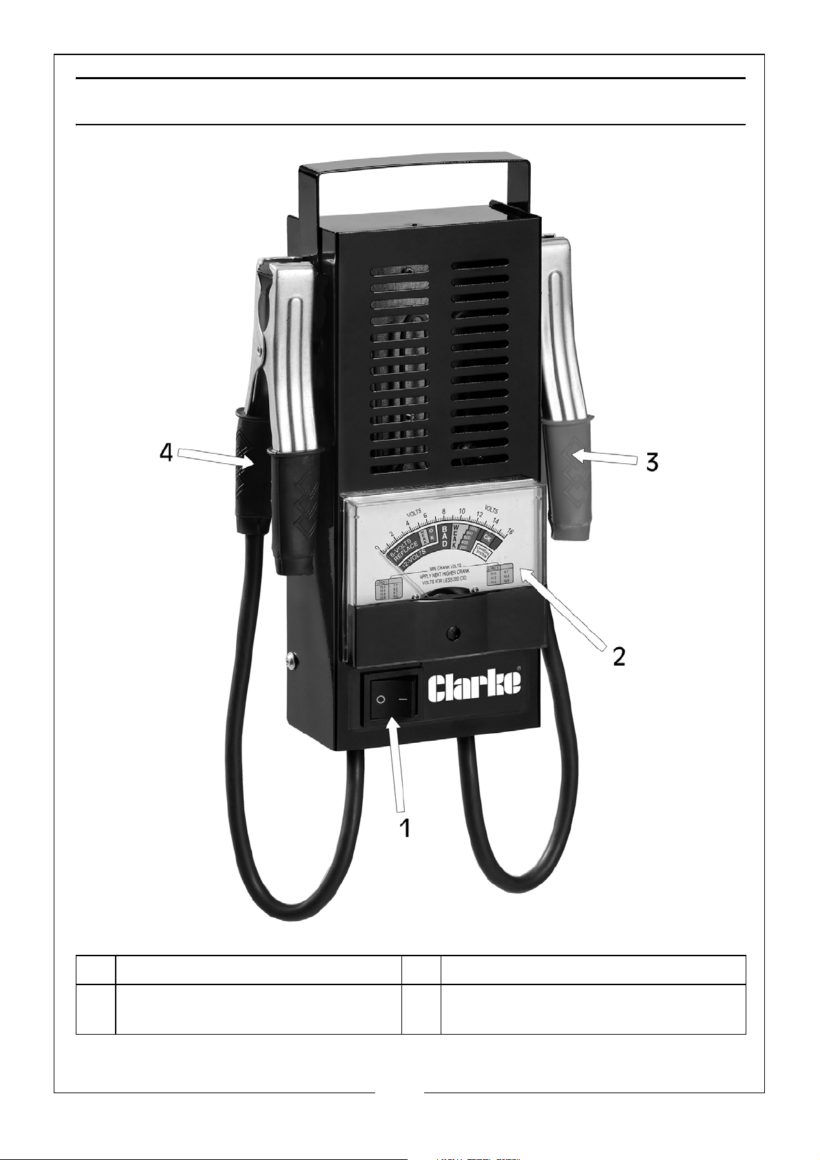
1 Battery Load Test Switch 2 Voltmeter Display
3 Red/Positive Crocodile Clip Test
Lead
Parts & Service: 020 8988 7400 / E-mail: [email protected] or [email protected]
4 Black/Negative Crocodile Clip
Test Lead
5
Page 6
BATTERY TESTER OPERATION
WARNING: ON THE FIRST LOAD TEST, SMOKE MAY BE EMITTED FROM THE
LOUVRES IN THE CASING. THIS IS NORMAL AND TEMPORARY.
BATTERY LOAD TEST
1. Attach the red/positive crocodile clip test lead to the red/positive (+)
battery terminal.
2. Attach the black/negative crocodile clip test lead to the black/negative
(-) battery terminal.
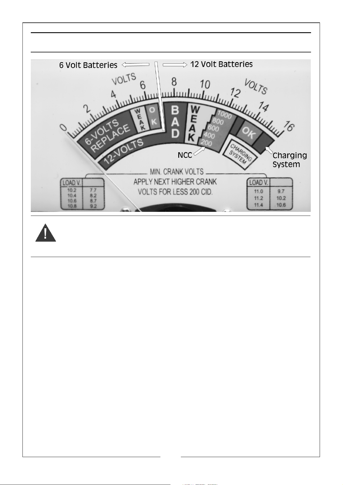
NOTE: Correct connection of the terminals will send the pointer clockwise
(right) across the voltage scale, incorrect connection will send the
pointer anticlockwise (left). If there is no movement of the pointer, there
is either a bad connection of the battery terminals or the battery is
dead.
3. Press the battery load test switch to the on position (I) and hold until the
voltmeter stabilises or for a maximum of 10 seconds.
NOTE: Failure to release the switch within 10 seconds may result in the switch
burning out.
4. Note the meter reading and then release the battery load test switch.
6
Parts & Service: 020 8988 7400 / E-mail: [email protected] or [email protected]
Page 7
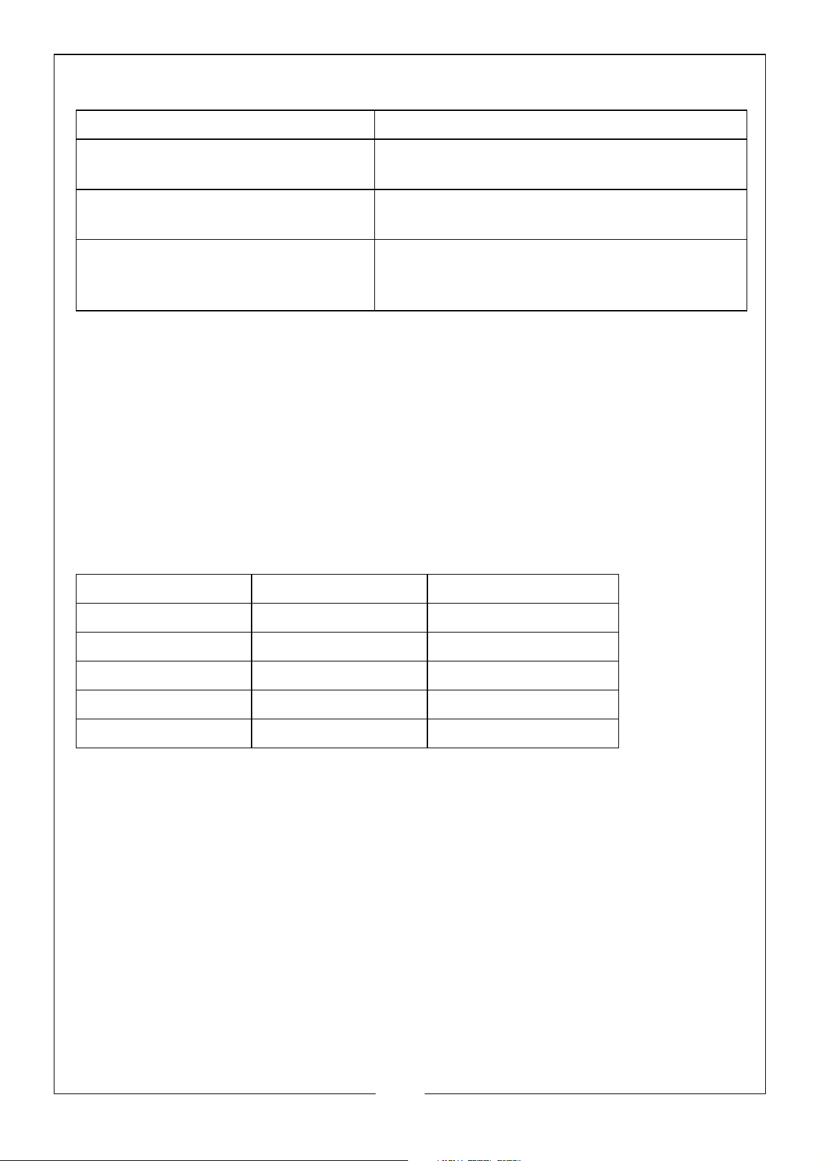
5. The following chart will show the condition of the battery.
Pointer Location Battery Condition
Green: ‘OK’ Battery is in a good condition and near
full charge
Yellow: ‘Weak’ Battery condition is low and may need
charging.
Red: ‘Bad’ Battery condition is very low and needs
charging. If battery still shows Red after
charging, replace the battery.
NOTE: For 12 volt batteries, the Green: ‘OK’ section is marked with Nominal
Cranking Current (NCC) from 200 to 1000 amps in 200 amp intervals.
Note this figure and compare with the battery manufacturers quoted
figure to give an indication of any deterioration.
BATTERY VOLTAGE/CHARGE LEVEL
1. If the load test results indicates a battery fault (yellow/red), allow the
battery to stabilise for a few minutes and then read the open circuit
voltage, which is a meter reading not utilizing the load switch.
2. Use the following chart to estimate the charge level
6 Volt Battery 12 Volt Battery Charge%
5.8 or Lower 11.7 or Lower 0
6.0 12.0 25
6.1 12.2 50
6.2 12.4 75
6.3 or Higher 12.6 or Higher 100
NOTE: The battery is considered charged at 75% or higher. If it fails the load
test with this charge, it should be replaced. If the voltage indicates a
charge below 75%, then charge the battery and retest. If the battery
fails a second time, replace it.
CHARGING SYSTEM (12 VOLT SYSTEM ONLY)
1. Attach the red/positive crocodile clip test lead to the red/positive (+)
battery terminal.
2. Attach the black/negative crocodile clip test lead to the black/negative
(-) battery terminal.
NOTE: Correct connection of the terminals will send the pointer clockwise
(right) across the voltage scale, incorrect connection will send the
pointer anticlockwise (left). If there is no movement of the pointer, there
7
Parts & Service: 020 8988 7400 / E-mail: [email protected] or [email protected]
Page 8

is either a bad connection of the battery terminals or the battery is
dead.
3. Start the engine and allow it to warm up. Turn off all electrical accessories
such as radio, headlights, heating etc.
4. Run the engine to between 1200 & 1500rpm and note the reading. This
should be in the green zone (OK), between 13.6V & 15V.
NOTE: DO NOT press the battery load test switch.
5. Switch on the headlights and heater system to its maximum. The meter
reading should stay in the green zone.
6. A reading below 13.6V (red zone) indicates a fault in the charging system
and/or the battery is under charged. A reading above 15V (red zone)
indicates the battery is overcharged.
STARTER MOTOR (12 VOLT SYSTEM ONLY)
NOTE: This test requires the battery to be in a good charged condition of at
least 75% (9V).
1. Attach the red/positive crocodile clip test lead to the red/positive (+)
battery terminal.
2. Attach the black/negative crocodile clip test lead to the black/negative
(-) battery terminal.
NOTE: Correct connection of the terminals will send the pointer clockwise
(right) across the voltage scale, incorrect connection will send the
pointer anticlockwise (left). If there is no movement of the pointer, there
is either a bad connection of the battery terminals or the battery is
dead.
3. Disable the ignition system by removing the fuse. (consult the vehicle
manual for correct procedure and fuse).
4. Carry out a load test (see page 6) and note voltage reading.
5. Use the following table (also displayed on the lower half of the Voltmeter
display), determine the minimum cranking voltage.
Load Voltage Minimum Cranking Voltage
3.5L and Above Engine Size Below 3.5L Engine Size
10.2 7.7 8.2
10.4 8.2 8.7
10.6 8.7 9.2
10.8 9.2 9.7
11 9.7 10.2
8
Parts & Service: 020 8988 7400 / E-mail: [email protected] or [email protected]
Page 9
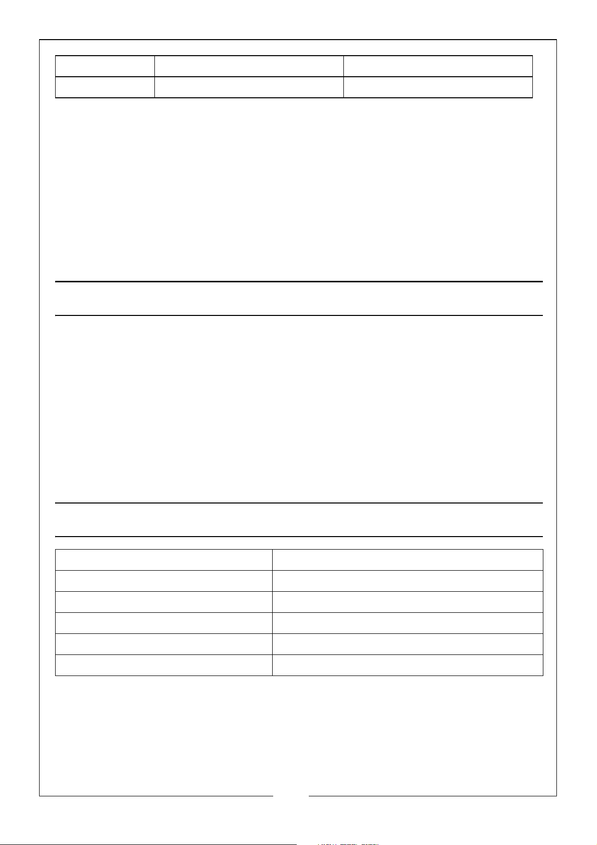
11.2 10.2 10.6
11.4 10.6 11.1
NOTE: An engine size of less than 3.5L, you should take the next higher
cranking voltage.
6. Operate the vehicle starter motor and note the voltage during cranking.
NOTE: DO NOT press the battery load test switch.
7. A reading below the minimum cranking voltage indicates that the starter
motor is taking too much current. This may be due to a poor connection, a
faulty starter motor or the battery being too small for the vehicle.
8. Reinstate the ignition system by replacing the fuse.
MAINTENANCE & CLEANING
• If needed, clean the device with a light, damp, soft cloth.
• Before cleaning, disconnect the device from the electrical system.
• DO NOT use any liquid cleaning product.
• DO NOT use any inflammable cleaning product.
• DO NOT submerge the device or spill any liquids over it.
• AV OI D engine oil, petrol, antifreeze and electrolyte from contacting the
tester as this may cause surface deterioration of the device.
SPECIFICATION
Model No. CVT3
Product Description 6V & 12V Analogue Battery Tester
Part number 6260104
Input Voltage 0V - 16V DC
Measurement (H x W x D) 300 x 160 x 70mm
Product Weight 963g
9
Parts & Service: 020 8988 7400 / E-mail: [email protected] or [email protected]
Page 10
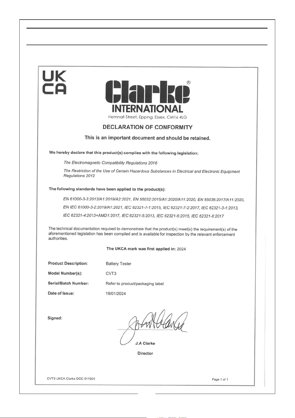
DECLARATION OF CONFORMITY - UKCA
10
Parts & Service: 020 8988 7400 / E-mail: [email protected] or [email protected]
Page 11
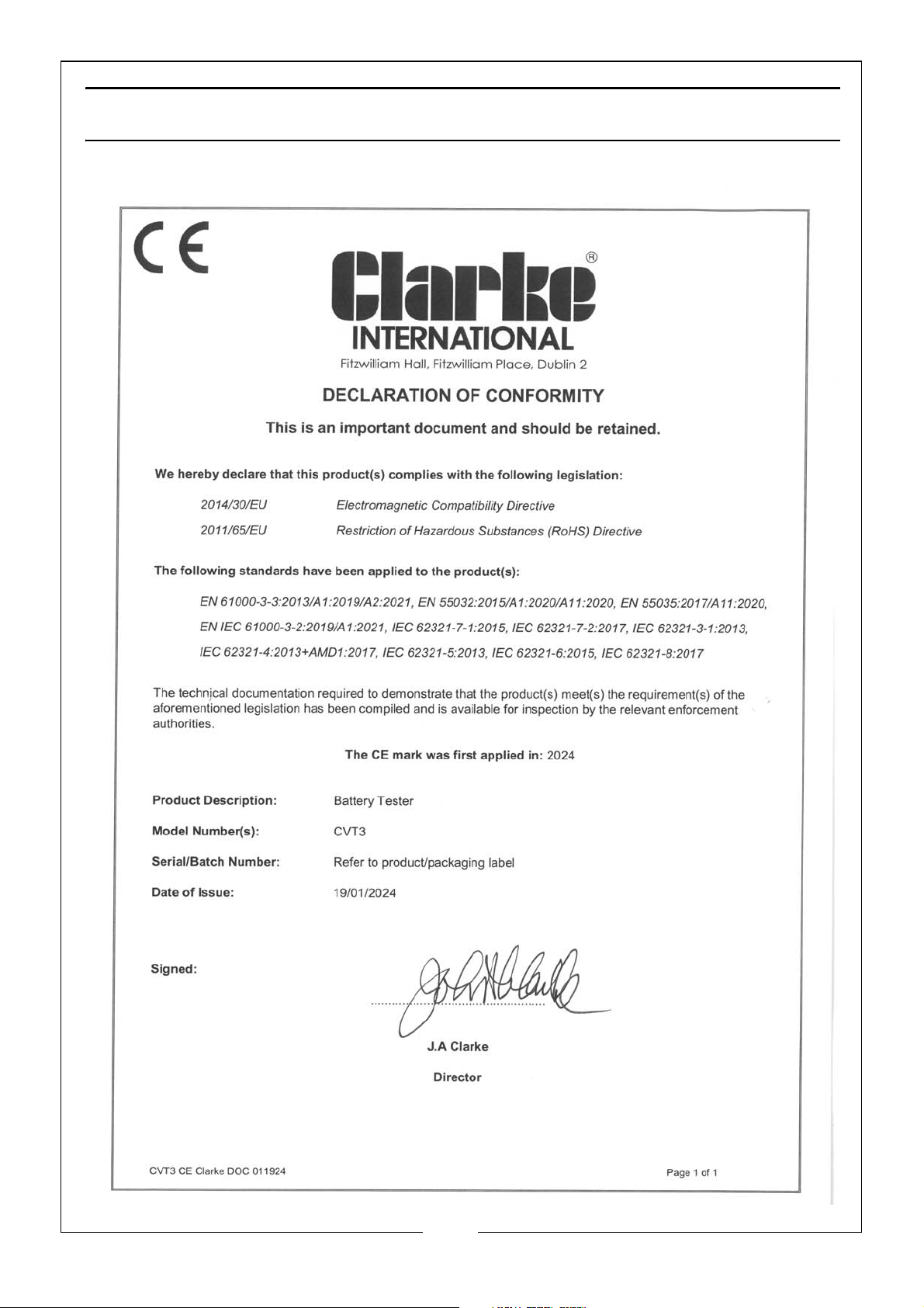
DECLARATION OF CONFORMITY - CE
11
Parts & Service: 020 8988 7400 / E-mail: [email protected] or [email protected]
Page 12

 Loading...