

Page 1
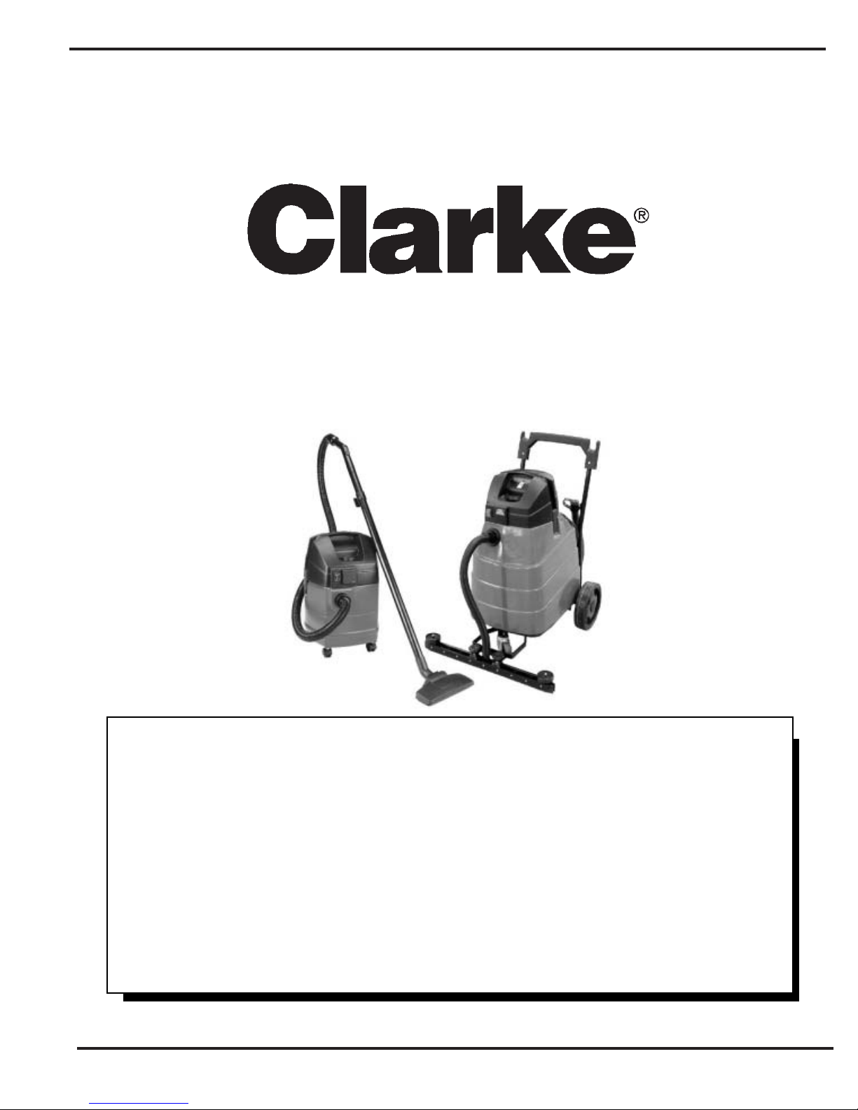
Operator's Manual
CTV
Manuel d'utilisation
Libro de Instrucciones
READ THIS BOOK
This book has important information for the use and safe operation of this machine. Failure to read
this book prior to operating or attempting any service or maintenance procedure to your Clarke
machine could result in injury to you or to other personnel; damage to the machine or to other property
could occur as well. You must have training in the operation of this machine before using it. If your
operator(s) cannot read English, have this manual explained fully before attempting to operate this
machine.
Wet/Dry V acuum
120V
All directions given in this book are as seen from the operator’s position at the rear of the machine.
For new books write to: Clarke
Form No. 70973A 3/05 Clarke® Printed in the U.S.A.
®
, 2100 Highway 265, Springdale, Arkansas 72764.
Page 2

T able of Contents
Important Safety Instructions ....................................................................................5
Specifications and Accessories ..............................................................................11
Grounding Instructions .............................................................................................14
How T o Assemble the Machine................................................................................16
How T o Prepare The Machine For Operation...........................................................16
Machine Operation..................................................................................................18
Maintenance and Repair .........................................................................................22
Troubleshooting.......................................................................................................2 4
Recommended Spare Part s....................................................................................25
Section II Parts and Service Manual
CTV 15 & 20 Head Assembly Drawing...................................................................30
Parts List .......................................................................................................31
CTV 7 Assembly Drawing .......................................................................................32
Parts List .......................................................................................................33
CTV 15 & 20 Tank Assembly Drawing and Parts List............................................... 34
CTV 15 & 20 Frame Assembly Drawing and Part s List ...........................................35
CTV 7, 15 & 20 Squeegee Assembly Drawing ........................................................36
Parts List ........................................................................................................37
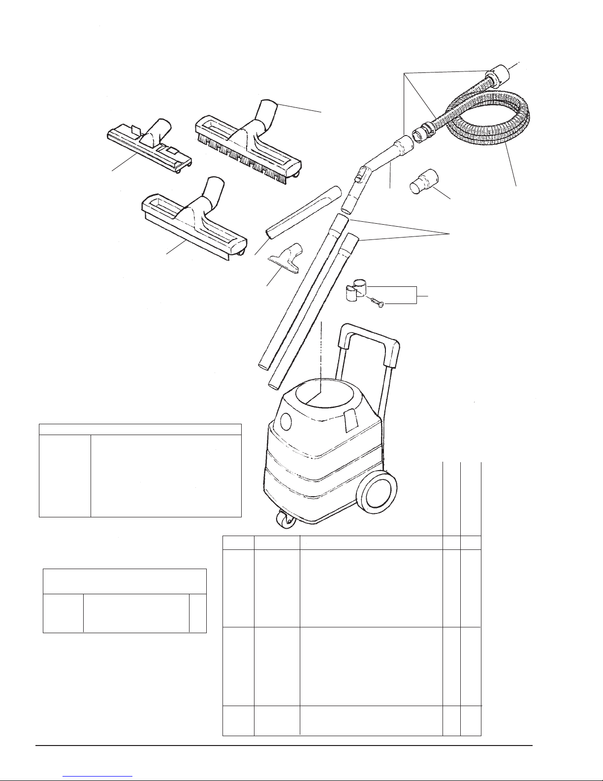
CTV 7, 15 & 20 Accessory Tools............................................................................. 38
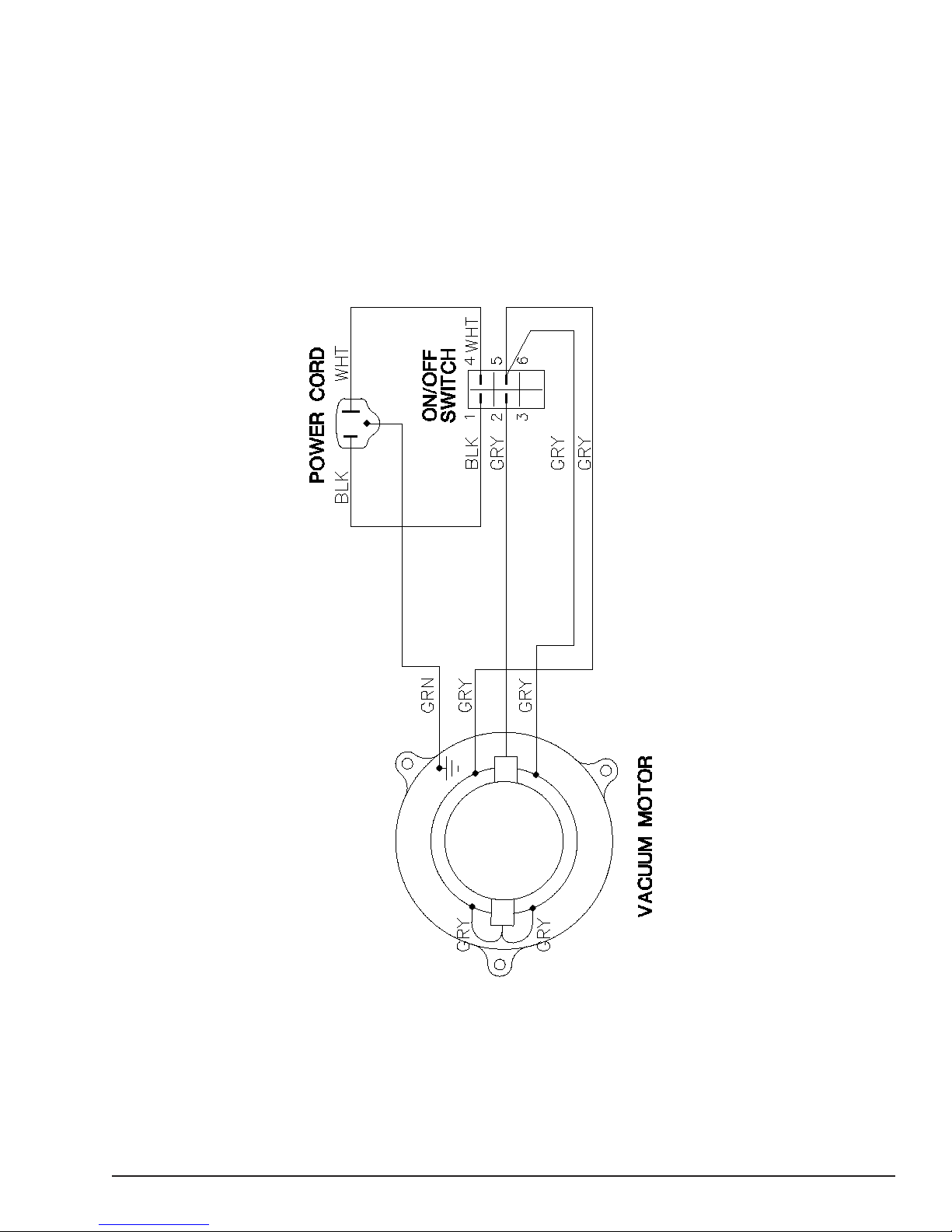
CTV 15 & 20 Electrical Schematic ..........................................................................39
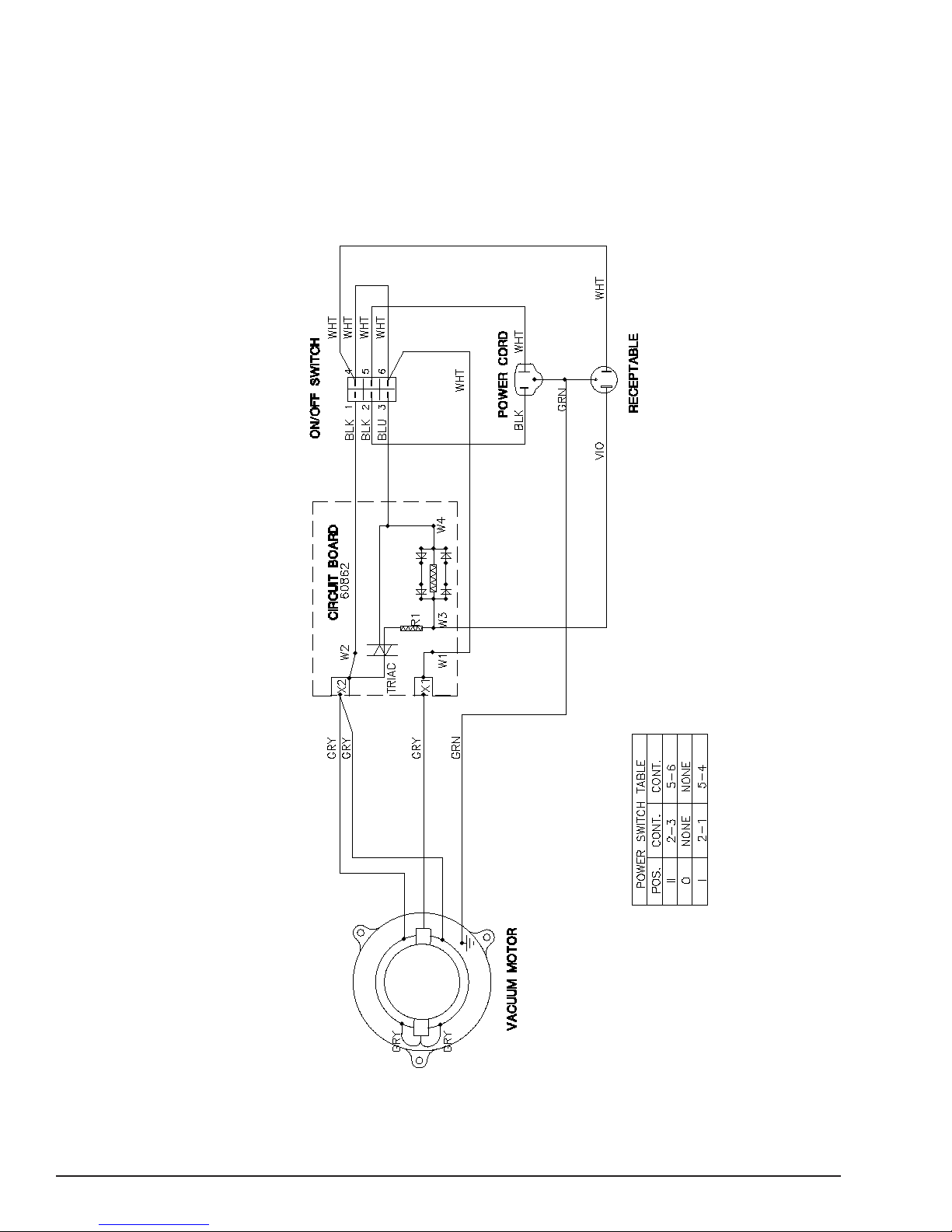
CTV 7 Electrical Schematic ....................................................................................40
Page -2- Clarke® Wet/Dry Vacuums Operator's Manual
Page 3
IMPORTANT SAFETY INSTRUCTIONS
WARNING AVERTISSEMENT ADVERTENCIA
DANGER: Failure to read and observe all DANGER statements could result in severe
bodily injury or death. Read and observe all DANGER statements found in
your Owner's Manual and on your machine.
WARNING: Failure to read and observe all WARNING statements could result in injury
to you or to other personnel; property damage could occur as well. Read
and observe all WARNING statements found in your Owner's Manual and on
your machine.
CAUTION: Failure to read and observe all CAUTION statements could result in damage
to the machine or to other property. Read and observe all CAUTION
statements found in your Owner's Manual and on your machine.
WARNING: To reduce the risk of fire, electric shock, or injury:
1. Do not leave machine when plugged in. Unplug from outlet when not in use and
before servicing.
2. To reduce the risk of electric shock use indoors only.
3. Do not allow to be used as a toy. Close attention is necessary when used by or
near children.
4. Use only as described in the manual. Use only manufacturer's recommended atattachments.
5. Do not use with damaged cord or plug. If machine is not working as it should, has
been dropped, damaged, left outdoors, or dropped into water, return it to a service
center.
6. Do not pull or carry by cord, use cord as a handle, close a door on cord, or pull cord
around sharp edges or corners. Do not run machine over cord. Keep cord away
from heated surfaces.
7. Do not unplug by pulling on cord. To unplug, grasp the plug, not the cord.
8. Do not handle plug or machine with wet hands.
9. Do not put any object into openings. Do not use with any opening blocked; keep
free of dust, lint, hair and anything that may reduce air flow.
10. Keep hair, loose clothing, fingers, and all parts of body away from openings and
moving parts.
11. The following materials must not be picked up with the machine: Hot materials
(glowing cigarettes, hot ashes, etc.); Inflammable, explosive or aggressive fluids (e.g.
gasoline, solvents, acids, alkalines, etc.); Inflammable, explosive dusts (e.g.
magnesium or aluminum dust, etc.).
12. Do not use without dust bag and/or filters in place. Use the machine only with an
undamaged filter element.
13. Turn off all controls before unplugging.
14. Use extra care when cleaning on stairs.
16. Connect to properly grounded outlet. See "Grounding Instructions".
SAVE THESE INSTRUCTIONS
Clarke
®
Wet/Dry Vacuums Operator's Manual
Page -5-
Page 4

DANGER: Failure to read the Owner's Manual prior to operating or attempting any service
or maintenance procedure to your Clarke machine could result in injury toyou
or to other personnel; damage to the machine or to other property could occur
as well. You must have training in the operation of this machine before using it.
If your operator(s) cannot read English, have this manual explained fully before
attempting to operate this machine.
DANGER: Operating a machine that is not completely or fully assembled could result in
injury or property damage. Do not operate this machine until it is completely
assembled. Inspect the machine carefully before operation. Use only as
described in this manual. Use only Clarke's recommended
attachments and replacement parts.
WARNING: Operating a machine without observing all labels, decals, etc., could result in
injury or damage. Read all machine labels before attempting to operate the
machine. Make sure all of the labels are attached or fastened to the machine.
Get replacement labels and decals from your Clarke distributor.
WARNING: Before connecting any appliance to the appliance plug socket, the machine must
always be switched off. If appliances are connected to the appliance plug
socket, ensure that these appliances are also switched off when being
connected to the appliance plug socket. See "Appliance Plug Socket" in the
"Grounding Instructions" section in of this manual.
CAUTION: Making technical modifications to the machine could endanger your safety. Do
not make any technical modifications to the machine.
CAUTION: Never spray the top section of the machine with water. Can cause danger to
persons or danger of short circuits.
CAUTION: Wrap cord around handle when machine is not in use. Use caution not to run
over cord while machine is in use.
CAUTION: This machine is not suitable for picking up health endangering dust.
CAUTION: If foam/liquid comes out, switch off immediately.
Page -6- Clarke® Wet/Dry Vacuums Operator's Manual
Page 5
SPECIFICATIONS & ACCESSORIES
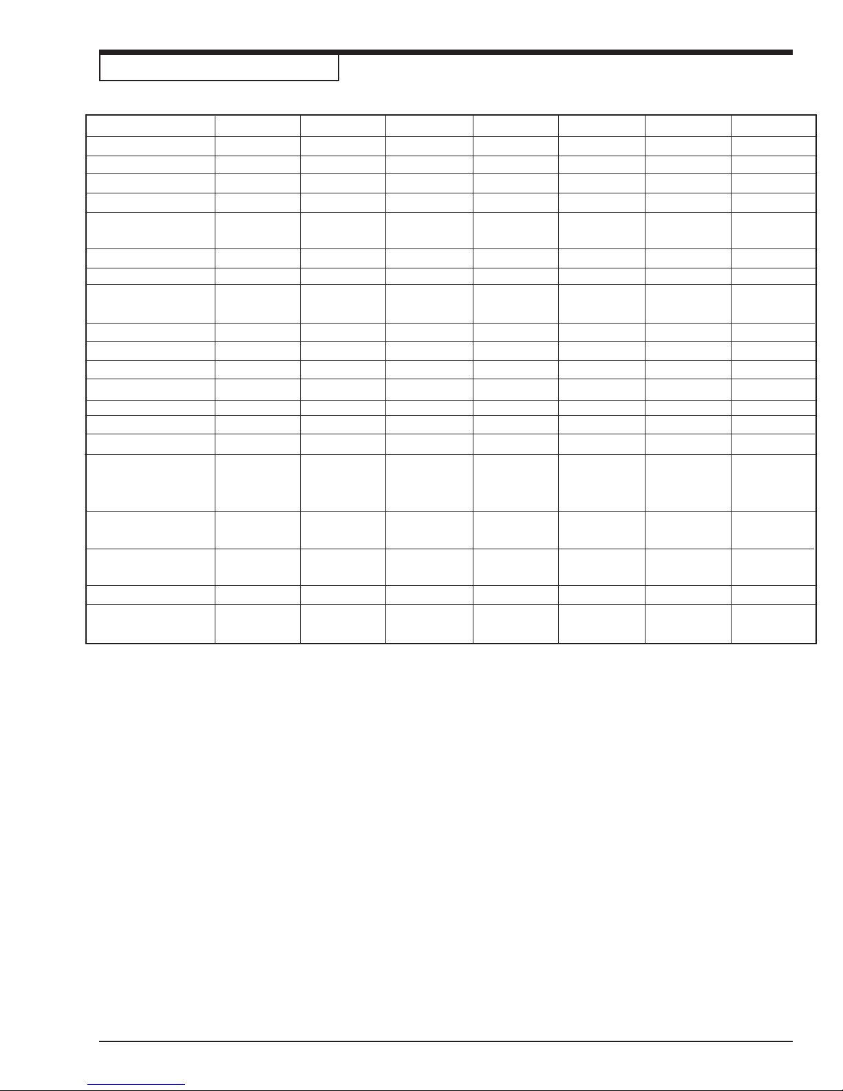
Model Code # 02170A 02172A 02174B 02176B 02178B 02180B 02182B
Model Description CTV7 CTV7 w/AS/E CTV15 CTV15 CTV20 CTV15 w/squ. CTV20 w/squ.
Voltage (V) 120 120 120 120 120 120 120
Frequency (Hz) 50/60 50/60 50/60 50/60 50/60 50/60 50/60
Power (Watts) 1200 1300 1200 1300 1300 1300 1300
Connected load for --- 600 Watts --- --- --- --- --appliance plug socket
Volume Air Flow(CFM) 12 0 1 10 1 20 1 10 1 10 1 10 1 10
Vacuum Motor Single Stage Dual Stage Single Stage Dual Stage Dual Stage Dual Stage Dual Stage
(inches)
Static Water Lift
(inches H
20)
Cord Length (feet) 1 6 16 50 5 0 50 50 50
Tank Volume (gal.) 7 7 15 15 20 1 5 20
Width (inches) 14.5 14.5 24 24 24 24 24
Depth (inches) 14 14 24 24 2 4 24 24
Height (inches) 21 21 38 38 38 38 38
Weight (lbs) Machine 14 1 6 44 4 5 48 4 5 48
Weight (lbs) Shipping 16 18 48 4 9 52 61 6 4
Order # for bag-type
filter elements 60910 60910 70007041 70007041 70007041 70007041 70007041
(pack of 5)
Order # for permanent
filter element (unit) 11754000 11754000 11754000 11754000 11754000 11754000 11754000
Clothe Filter Liner /
Washable 61156103 61156103 61156103 61156103 61156103 61156103 61156103
Squeegee Floor Tool --- --- --- --- --- 70007035 70007035
Replacement
Squeegee Blades --- --- --- --- --- 30292A 30292A
65 95 65 95 95 95 95
.
Clarke
®
Wet/Dry Vacuums Operator's Manual
Page -11-
Page 6
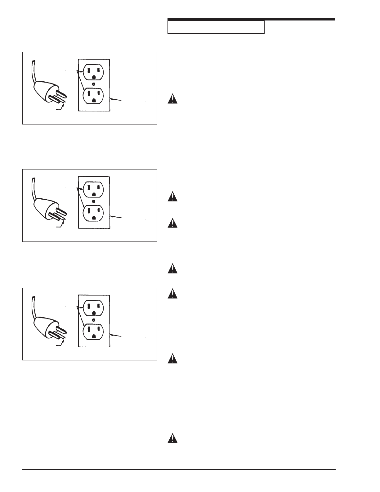
Grounding
Pin
Terminal
de tierra
Grounded
Outlet
Figure 1
Toma
corriente
con polo
de tierra
Figure 1a
(A)
(A)
Grounded
Outlet
Box
Tapa del toma
corriente con
polo de tierra.
GROUNDING INSTRUCTIONS
This appliance must be grounded. If it should malfunction or
breakdown, grounding provides a path of least resistance for
electric current to reduce the risk of electric shock. This
appliance is equipped with a cord having an equipmentgrounding conductor and grounding plug. The plug must be
plugged into an appropriate outlet that is properly installed
and grounded in accordance with all local codes and ordinances.
WARNING: Improper connection of the equipmentgrounding conductor can result in a risk of electric
shock. Check with a qualified electrician or service
person if you are in doubt as to whether the outlet
is properly grounded. Do not modify the plug
provided with the product - if it will not fit the
outlet, have a proper outlet installed by a qualified
electrician.
This appliance is for use on a nominal 120-volt circuit and
has a ground plug that looks like the plug illustrated in figure
1. Make sure that the appliance is connected to an outlet
having the same configuration as the plug. No adapter
should be used with this appliance.
WARNING: To prevent possible electric shock, protect
the machine from rain. Keep the machine in a dry
building.
WARNING: To prevent possible electric shock, always
use a 3-wire electrical system connected to the electrical ground. For maximum protection against electrical shock, use a circuit that is protected by a ground
fault circuit interrupter. Consult your electrical contractor.
Broche de
mise à la
terre
Prise de
courant
avec mise
à la tere
Figure 1b
(A)
Boîte de
sortie mise à
la terre
WARNING: Do not cut, remove or break the ground
pin. If the outlet does not fit the plug, consult your
electrical contractor.
WARNING: Have worn, cut or damaged
cords replaced by an authorized service person.
EXTENSION CORDS
Use only an approved extension cord with three conductors,
a plug with three terminals, and a connector body with three
holes. The machine has a power cord with wire size 16
AWG (AWG means American Wire Gauge).
WARNING: If you use an extension cord, use an
extension cord with minimum wire size 14 AWG.
Do not use an extension cord longer than 50 feet.
Do not join two extension cords.
APPLIANCE PLUG SOCKET
Before connecting any appliance to the appliance plug
socket, the machine must always be switched off. If appliances are connected to the appliance plug socket, ensure
that these appliances are also switched off when being
connected to the appliance plug socket.
CAUTION: The operating instructions and the safety
precautions contained therein must be observed
when using appliances connected to the appliance
plug socket of the machine.
Page -14- Clarke® Wet/Dry Vacuums Operator's Manual
Page 7
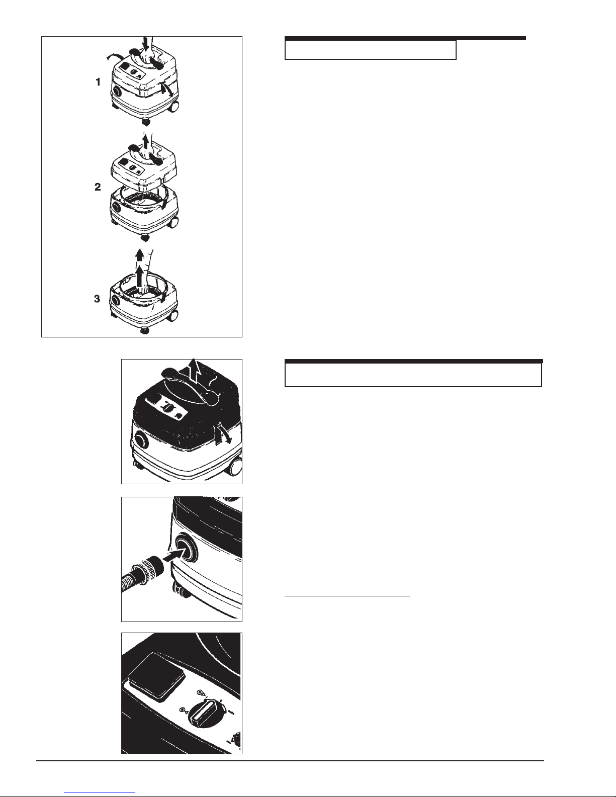
Figure 2
HOW TO ASSEMBLE THE MACHINE
CAUTION!
On delivery , the accessories - are lying in the tank and
must be removed before the machine is used for the first
time. See figure 2 (figure is for CTV 7, but other units are
similar).
T o assemble the machine, remove the machine top
section:
The power cord must not yet be inserted into a plug
socket.
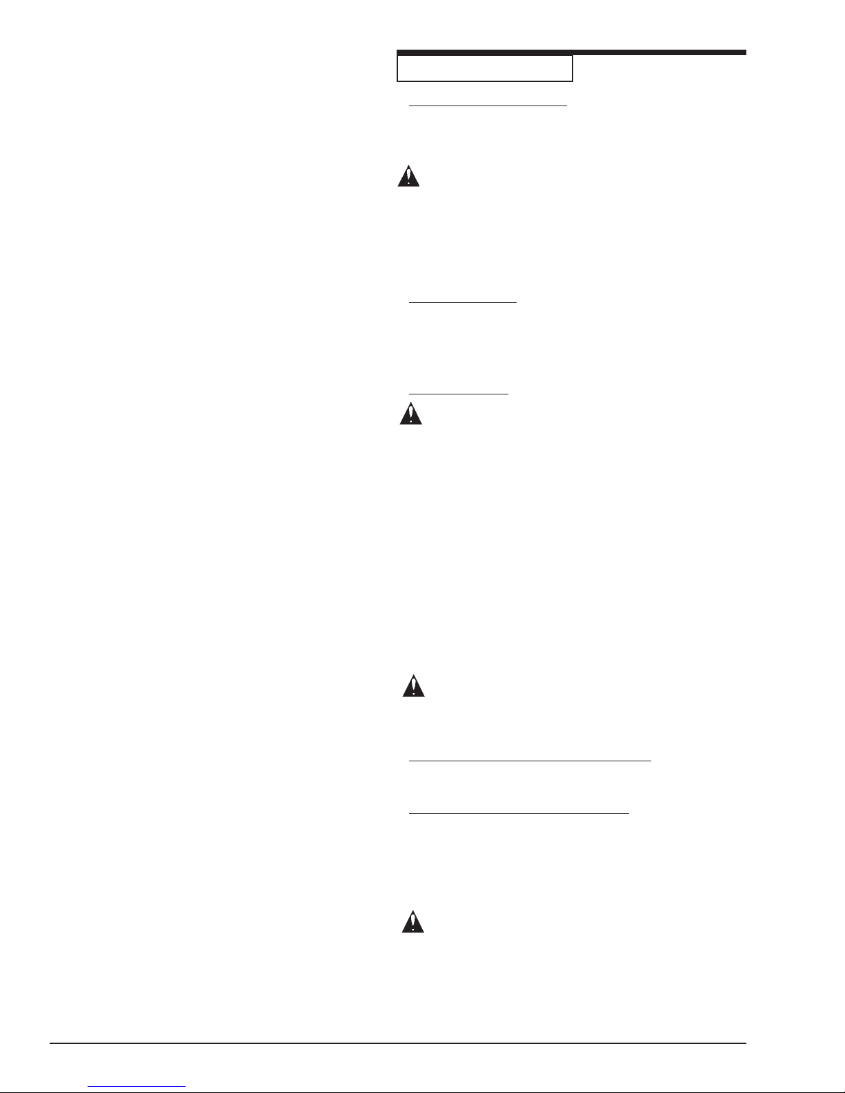
1. Open the retaining clamps and lift off the machine top
section (Figure 3).
2. Place a bag-type filter into the tank as described in the
instructions printed on the filter.
3. Fit the machine top section back on the tank, and close
the retaining clamps.
4. Connect the suction hose. The "Wap Multifit" enables
any Clarke suction hoses (27, 32, 36, 50 mm diameter)
to be connected to the machine (Figure 4).
Figure 3
Figure 4
HOW TO PREPARE THE MACHINE FOR OPERA TION
T o prepare the machine for operation, follow this procedure:
1. Remove tool kit from carton.
2. Remove head assembly from tank before removing tank
from carton.
3. Remove tank assembly from carton.
4. Attach head assembly to tank.
Ensure that the machine is switched off and insert the
plug of the power cord into a properly installed and fused
plug socket with ground.
Connecting Electric Tools - (For CTV 7 AS)
Connect the electric tool to the appliance plug socket on
the control panel (Figure 5).
Before connecting a tool, ensure that both the machine and
the tool are switched off.
Figure 5
Page -16- Clarke® Wet/Dry Vacuums Operator's Manual
For maximum power consumption of the electric tool to be
connected, see the Specification T able on p age 5.
Page 8
MACHINE OPERATION
Picking Up Dry Substances
Before picking up dry substances, the bag-type filter should
always be installed in the tank. It is then easy to dispose of
the material picked up and the service life of the main filter
element is significantly increased.
WARNING: Inflammable substances must not be
picked up with the machine!
After picking up liquids, the filter element is damp. Damp
filter elements can clog more quickly when dry substances
are picked up. For this reason, the filter element should be
dried or replaced before picking up any dry substances.
Picking Up Liquids
For both wet and dry applications be sure to leave the
cartridge filter and the cloth filter in place around the float
cage. Also be sure to frequently clean the filters. This is
especially true when the vacuum is being used with
strippers and wax.
Daily Maintenance
CAUTION: Strippers and some detergents produce
foam which will damage the vacuum motors. The
vacuum float shut-off may not be sensitive to all
foams. Be sure to check that the tank is not filling
with foam. Use a defoaming agent to avoid pulling
foam through the vacuum motor. Should the vacuum
motor become wet, remove source of overflow and
immediately run vacuum motor open to purge the
motor dry. Both the cartridge filter and the cloth filter
should be rinsed and dried to remove stripper or wax.
Do not allow stripper or wax to dry in the filters, as
this will adversely affect performance.
1. Drain and rinse tank and remove head assembly to
allow drying.
2. Remove, rinse, and clean filters and allow to dry.
3. Inspect the power cord and hoses for damage.
WARNING: Inflammable liquids must not be picked up
with the machine!
Switching On The Machine (CTV 7, 15, 20)
Turn the switch to position "I" .
Switching On The Machine (CTV 7 AS)
Two operating modes are possible.
1. Switch position "I":
The machine motor starts immediately.
2. Switch position "auto":
The machine motor starts only when the tool connected to the appliance plug socket is switched on.
CAUTION: Before turning the switch to position
"auto", ensure that the tool connected to the appliance plug socket is switched off.
The motor speed and thus the suction power can be varied
at the suction force regulator. This permits a precise
adaptation to different substances to be picked up.
Page -18- Clarke® Wet/Dry Vacuums Operator's Manual
Page 9

Figure 6
MACHINE OPERA TION
Operating The Machine
If using machine for liquid pickup, follow this procedure:
1. Leave filter cartridge and cloth filter in place.
NOTE: This machine has a float shut-off.
When the water raises the float, the air
stops moving through the machine.
2. Turn machine on and begin vacuuming. The ON/OFF
switch is on top of the vacuum head assembly . Put
the switch in the "I" position to start the motor. Put the
switch in the "O" position to stop the motor.
3. When cleanup is complete, empty the liquid by
opening the drain valve on the drain hose. See figure
6.
4. For best performance, clean and rinse cloth and
permanent filters.
If using for dry pickup or to remove shampoo from
carpet, follow this procedure:
1. Use the filter bag. This will keep debris from entering
the vacuum motor.
2. Turn machine on and begin vacuuming. If pickup
efficiency decreases, stop the machine.
3. Remove the foam, liquid, dirt and carpet fibers from
the tank and from the filter bag.
NOTE: Have an extra clean filter bag avail
able for continuous operation. Use clean filter bag
while other filter bag is being laundered and dried.
4. For best performance, clean the mesh screen around
the float often.
There are no user serviceable part s. All repairs
must be done by authorized personnel only.
After Finishing Work
1. Switch off the machine and pull the plug of the power
cord out of the plug socket.
2. Wind up the power cord.
Page -20- Clarke® Wet/Dry Vacuums Operator's Manual
Page 10
MACHINE OPERATION
Changing The Bag Type Filter
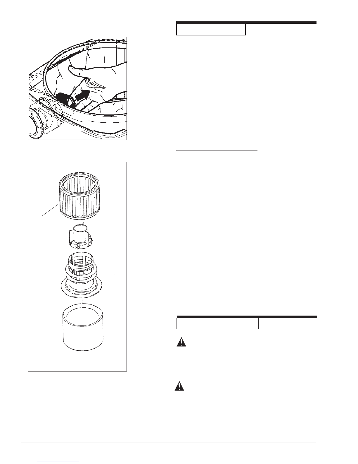
1. Pull the bag-type filter sleeve off the inlet fitting.
See Figure 7.
2. Dispose of the used bag-type filter in accordance
with the local waste disposal regulations.
3. Place a new bag-type filter into the tank as described in the instructions printed on the filter.
IMPORT ANT!
Push the bag-type filter sleeve completely
onto the inlet fitting.
Figure 7
Replacing The Filter Element
1. Switch off the machine and pull the plug of the
power cord out of the plug socket.
2. Remove the machine top section from the dirt tank
and place to one side with the filter element facing
upwards (Figure 8).
3. Remove the outer strainer filter bag.
2
4. Unscrew the filter retaining nut (1) and remove.
5. Pull off the filter element (2).
6. Push on a new filter element.
7. Fit the filter retaining washer and tighten the
retaining nut.
8. Dispose of the used filter element in accordance
with the local waste disposal regulations.
9. Reinstall the outer strainer filter bag.
Figure 8
Page -22- Clarke® Wet/Dry Vacuums Operator's Manual
MAINTENANCE AND REP AIR
CAUTION: Before cleaning and servicing the
machine, always remove the power cord.
Carry out only maintenance operations described in
these operating instructions. Use only original Clarke
spare parts.
CAUTION: Do not make any technical
modifications to the machine. Y our safety
could be endangered as a result!
For all other maintenance and repair work,
please contact an authorized Clarke Service
department.
Page 11

TROUBLESHOOTING
Problem
Motor does not start
Reduced suction power
No suction power during
wet cleaning.
Problema
El motor no enciende.
1. The fuse or plug socket has blown.
2. Overload protection switch has tripped.
1. Bag-type filter full.
2. Suction hose clogged.
3. Filter element clogged.
1. Tank full (float switch closing off the
suction opening).
DETECCIÓN DE PROBLEMAS
1. Saltó el fusible o no funciona el tomacorriente.
2. Se disparó el mecanismo de interrupción por sobrecarga.
ActionCause
1. Reset the fuse
2. Allow the machine to cool down approximately
5 minutes; if the machine does not start again
automatically, contact the Service Dept.
1. Replace bag-type filter.
2. Clean suction hose.
3. Clean and replace filter element.
1. Empty tank.
AcciónCausa
1. Coloque nuevamente el fusible.
2. Deje que la máquina se enfríe por
aproximadamente 5 minutos; si la máquina no
vuelve a encenderse en forma automática, llame
al Departamento de servicio.
Baja potencia de aspiración.
No hay potencia de aspiración
durante la limpieza en
húmedo.
Problème
Le moteur ne démarre pas.
Force d'aspiration réduite.
1. Filtro tipo bolsa lleno.
2. Manguera de aspiración obstruida.
3. Elemento filtrante obstruido.
1. Depósito lleno (el interrupotor de flotación cierra la abertura de aspiración.)
DIAGNOSTIC
1. Le fusible ou la prise a sauté.
2. Le commutateur de protection contre les
surcharges s'est décienché.
1. Le filtre de type sac est plein.
2. Le tuyau d'aspiration est bouché
3. L'élément de filtrage est bouché.
1. Cambie el filtro tipo bolsa.
2. Limpie la manguera de aspiración.
3. Limpie y cambie el elemento filtrante.
1. Vacíe el depósito.
ActionCause
1. Replacez un fusible.
2. Laissez la machine refroidir pendant environ 5
minutes; si la machine ne démarre toujours pas
automatiquement, contactez le Service des
Réparations.
1. Remplacez le filtre de type sac.
2. Nettoyez le tuyau d'aspiration.
3. Nettoyez et replacez l'élément de filtrage.
Aucune force d'aspiration
pendant un nettoyage
humide.
Page -24- Clarke® Wet/Dry Vacuums Operator's Manual
1. Le réservoir est plein (le commutateur à
flotteur refermant l'ouverture d'aspiration).
1. Videz le réservoir.
Page 12

Clarke
CTV 7, 15 & 20
Recommended Spare Parts
®
Part No. Description
60608 Caster
60610 Gasket, Vacuum
60867 Switch, Main Power
11754000 Filter, Permanent
21448070 Knob, Squeegee
26771800 Cord, Power
26771900 Cord, Power
27000410 Frame, Squeegee Weldment
27000411 Retainer, Squeegee Blade
27000414 Wheel, Squeegee
30001200 Foam, 20 x 60
30001504 Hose, Vac (2 meter)
30001505 Hose, Vac (4 meter)
30001506 Hose, Tools Assembly (15/20 Gal.)
30001507 Hose, Drain Assembly
30001508 Hose, Squeegee
60608100 Caster
61156102 Filter Bag, 15/20 Gallon
70002112 Motor, Vacuum Single Stage
70003311 Motor, Vacuum Two Stage
70000316 Brush Carbon Single Stage
70000316 Brush Carbon Two Stage
70007035 Complete Squeegee Assembly Kit
70007039 Adapter, Hose to 1½" Wand
70020032 Wheel
60910 Filter Bag, 7 Gallon (pkg. of 5)
90000502 Hose, Tool Assembly (7 Gal.)
30292A Blade, Squeegee
Clarke
®
Wet/Dry Vacuums Operator's Manual
Page -25-
Page 13

CTV
Wet/Dry Vacuum
120V
Section II
Parts and Service
Clarke
®
Wet/Dry Vacuums Operator's Manual
(70973A)
Page -29-
Page 14
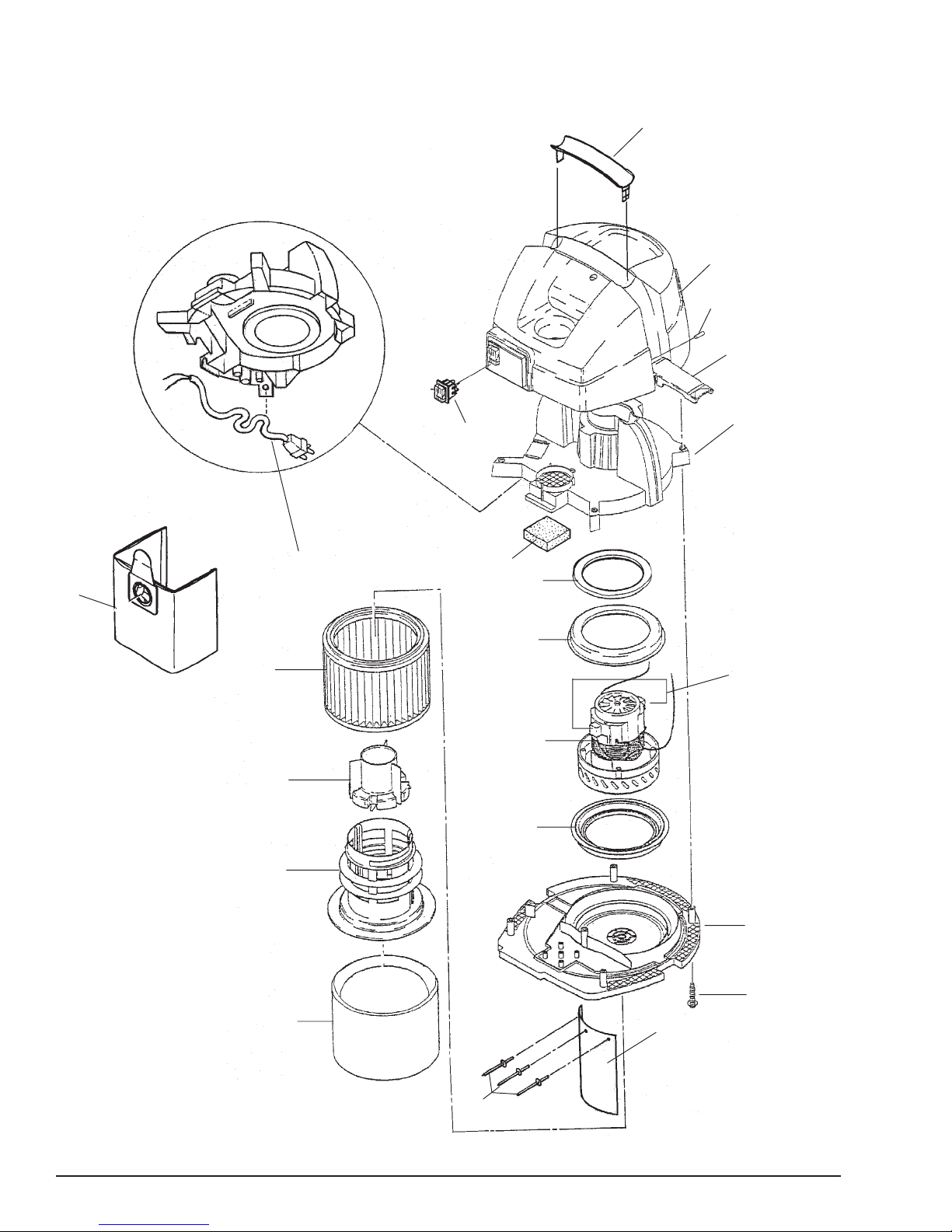
Clarke
CTV 15 & 20
Head Assembly Drawing 3/05
®
1
2
21
3
20
18
17
19
5
4
6
7
8
10
9
8
16
15
Page -30- Clarke® Wet/Dry Vacuums Operator's Manual
11
12
13
14
Page 15

Clarke
®
CTV 15 & 20
Head Assembly Parts List 3/05
02178B
02182B
02180B
02176B
Ref. Part No. Description Qty Qty Qty Qty Qty
1 60603000 Handle 1 1 1 1 1
2 60601000 Cover, T o p 1 1 1 1 1
3 538423 Clamp 2 2 2 2 2
4 60604000 Housing, Upper 1 1 1 1 1
5 60867 Switch, Main Power 1 1 1 1 1
6 30001200 Foam, 20 x 60 1 1 1 1 1
7 60610200 Ring Distance 1 1 1 1 8 60610 Gasket, Vacuum Motor 2 2 2 2 2
9 70002112Motor, 127V Single Stage - - - - 1
70003311Motor, 127V T wo St age 1 1 1 1 -
10 70000316Brush Carbon Motor (Single Stage) - - - - 1
70000316Brush Carbon Motor (Two Stage) 1 1 1 1 -
1 1 60605000 Housing, Bottom (Single Stage) - - - - 1
60605010 Housing, Bottom Two S t age 1 1 1 1 12 N A Screw, M5 x 20, Phillips Self Thread 5 5 5 5 5
13 27000436 Deflector , (Perm. Filter) 1 1 1 1 1
14 N A Rivet, 4mm x 12mm, Alum. Closed 3 3 3 3 3
15 61156103 Filter, Cloth 1 1 1 1 1
16 60607000 Cage, Float 1 1 1 1 1
17 60606000 Float 1 1 1 1 1
18 11754000 Filter , Permanent 1 1 1 1 1
19 26771900 Cord, Power 1 1 1 1 1
20 61156102Filter Bag, 15/20 Gal. 1 1 1 1 1
21 53839A PIn, 3/8 x 44 mm 2 2 2 2 2
02174B
NA = Not A vailable
NOTE: indicates a change has been made since the last publication of this manual.
Clarke
®
Wet/Dry Vacuums Operator's Manual
Page -31-
Page 16
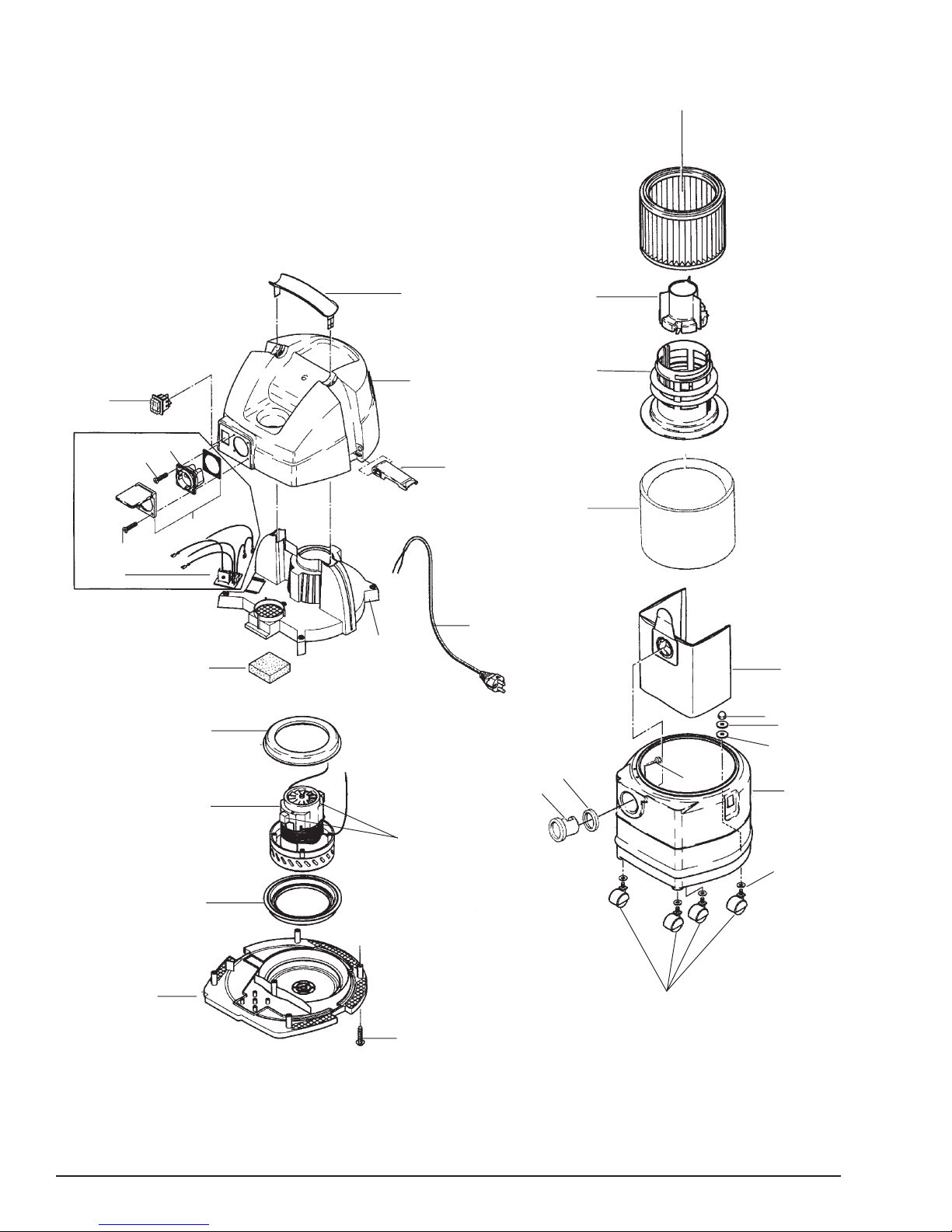
Clarke
Assembly Drawing 8/02
®
CTV 7
1
20
16
17
17
19
18
15
14
13
26
22
23
24
25
28
29
2
3
4
5
6
7
9
21
8
13
12
Page -32- Clarke® Wet/Dry Vacuums Operator's Manual
27
7
10
11
Page 17

Clarke
®
CTV 7
Assembly Parts List 10/03
02172A
Ref. Part No. Description QTY QTY
1 11754000 Filter Element, P .P. 1 1
2 60606000 Float 1 1
3 60607000 Cage, Float` 1 1
4 61 156103 Filter, Cloth 1 1
5 60910 Filter Bag, (pkg. of 5)` 1 1
6 2364 Cap Nut 4 4
7 2793 U-Disc 8.4 mm Zinc 4 4
8 90000136 Tan k 1 1
9 61276 Washer 4 4
10 60608 Caster, PVC 4 4
1 1 NA Screw, M 5 x 20, Phillips Self Threading 5 5
12 60605000 Bottom Housing, Single Stage - 1
60605010 Bottom Housing, Two S tage 1 13 60610 Motor Ring, Vac 2 2
14 70002112 Vac Motor , 120V Single S t age - 1
70003311 Vac Motor, 120V Two S tage 1 15 60611 Foam 1 1
16 62171 Automatic Start 1 17 46248 Screw, PT 3.5 x 16 4 18 46297 Plug Cover 1 19 49267 Plug Socket 1 20 60867 Switch - 1
1 1992 Switch Complete 1 21 N A Screw, M3.5 x .6 x 14 Shoulder , Hex 3 3
22 60603 Handle 1 1
23 60601000 Top Cover 1 1
24 26797 Clamp 2 2
25 26771800 Power Cord 1 1
26 60604000 Upper Housing 1 1
27 70000316 Brush Carbon (Set) 1 1
28 30000601 Inlet 1 1
29 30000602 Inlet, Seal 1 1
02170A
NA = Not A vailable
Clarke
®
Wet/Dry Vacuums Operator's Manual
Page -33-
Page 18
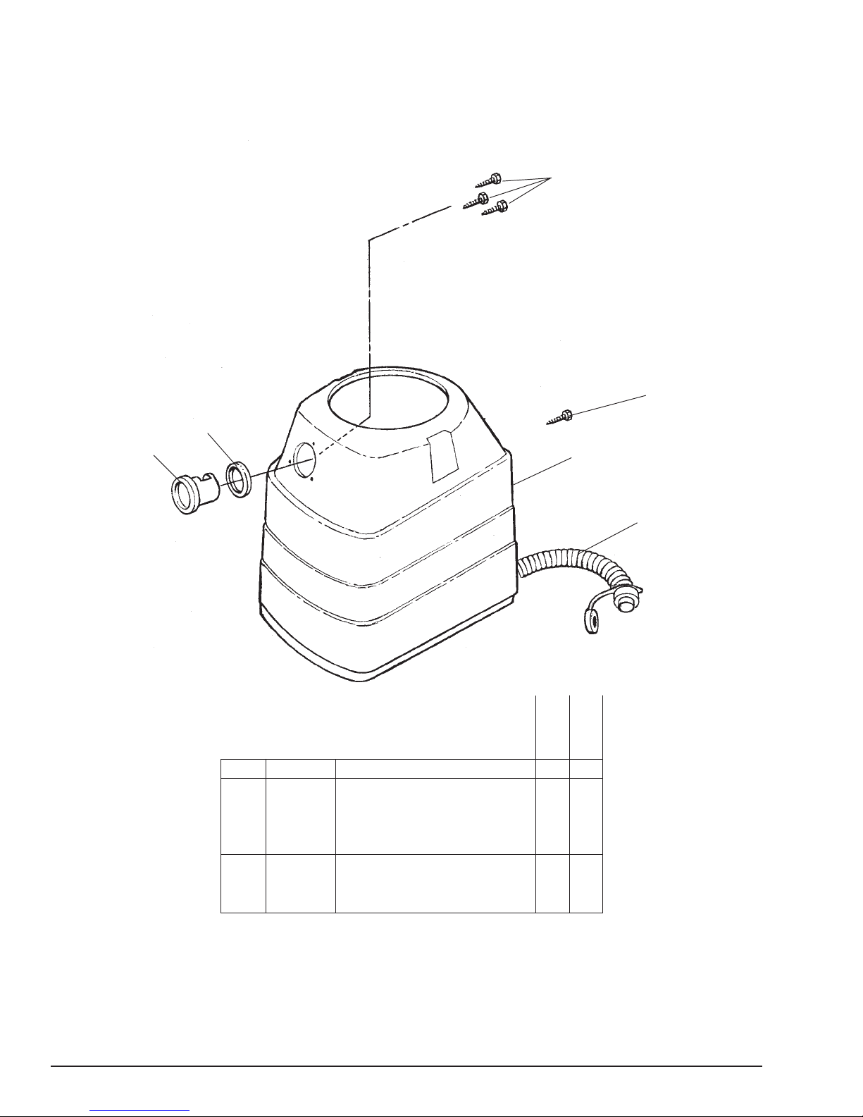
Clarke
®
CTV 15 & 20
Tank Assembly Drawing and Parts List 3/05
1
2
6
5
3
15 Gallon
Ref. Part No. Description Qty Qty.
1 50170 Screw, 3.5 x 14 3 3
2 NA Screw, M8 x 12 2 2
3 53840A Tank, 20 Gallons - 1
53841A Tank, 15 Gallons 1 4 30001507 Hose, Drain Assembly 1 1
5 30000601 Inlet 1 1
6 30000602 Inlet Seal 1 1
4
20 Gallon
NA = Not A vailable
NOTE: indicates a change has been made since the last publication of this manual.
Page -34- Clarke® Wet/Dry Vacuums Operator's Manual
Page 19
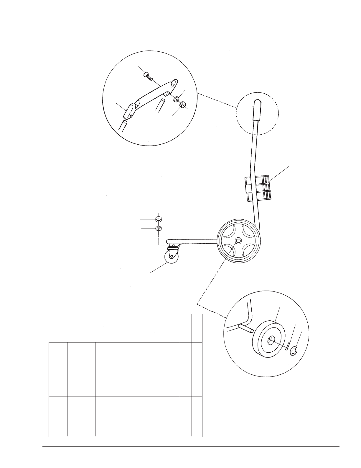
Clarke
®
CTV 15 & 20
Frame Assembly Drawing and Parts List 3/05
9
10
8
11
1
7
6
5
15 Gallons
Ref. Part No. Description Qty Qty
1 53843A Frame Weldment 1 1
2 70020032 Wheel 2 2
3 21532060 Retainer 2 2
4 70000145 Retainer, Cover 2 2
5 60608100 Caster 1 1
6 N A Washer, M8.4 x 17 x 1.5 1 1
7 NA Nut, M8 Hex 1 1
8 43625 Handle Bar SQ. 1 1
9 N A Screw, M6 x 40 Self Threading 2 2
10 N A Washer , M6.4 x 12.5 x 1.5 2 2
1 1 N A Nut, M6 Lock 2 2
2
3
4
20 Gallons
NA = Not Available
NOTE: indicates a change has been made since
the last publication of this manual.
Clarke
®
Wet/Dry Vacuums Operator's Manual
Page -35-
Page 20
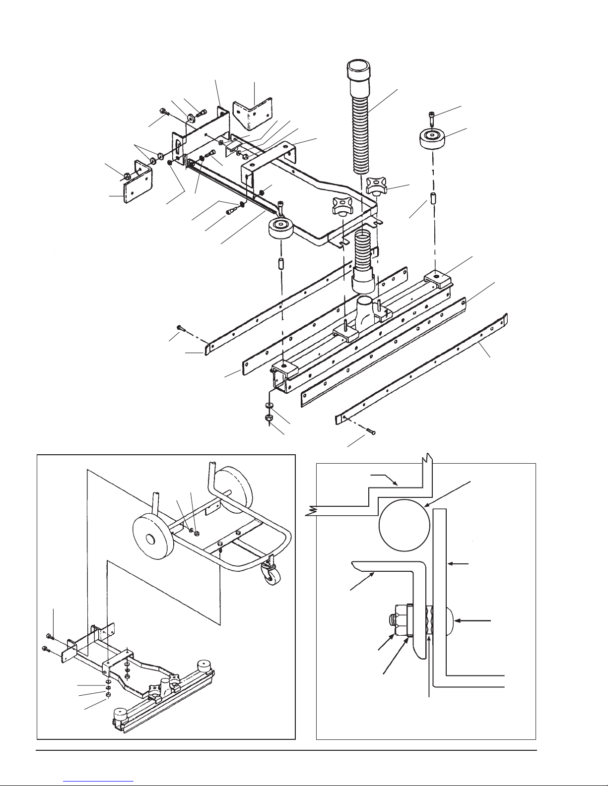
Clarke
CTV 7, 15 & 20
Squeegee Assembly Drawing 9/04
®
*As needed
18
19
21
25
18
12
17
11
16
17
17*
16
1
15
2
4
5
27
28
26
29
3
6
16
18
7
10
8
9
1
11
9
23
21
22
20
22
20
13
14
12
Tank
Tubular
Frame
Step
Bracket
27
25
29
28
26
FIGURE A
Page -36- Clarke® Wet/Dry Vacuums Operator's Manual
Page 21

Clarke
®
CTV 7, 15 & 20
Squeegee Assembly (70007035) Parts List 9/04
Ref. Part No. Description Qty
1 27000405 Pedal, Squeegee Lift 1
2 27000404 Support, Pedal Left 1
3 27000406 Support, Lift 1
4 30001508 Hose, Squeegee 1
5 N A Screw, M6 x 1 x 40 Shoulder Hex 2
6 27000414 Wheel 2
7 21448070 Knob 2
8 27000410 Frame, Squeegee Weldment 1
9 30292A Blade, Squeegee 2
10 27000415 Bushing, Wheel 2
1 1 27000411 Retainer, Squeegee Blade 2
12 N A Screw, M5 x 0.8 x 10 Phillips 18
13 N A Washer , M6.4 x 12.5 x 1.5 2
14 N A Nut, Lock M6 Lock 2
15 27000407 Lift, Squeegee Weldment 1
16 N A Bolt, Shoulder 1/2" x 1.25mm x 22mm 6
17 N A Washer, M10.5 x 21x 1.5 6
18 NA Nut, Lock M8 6
19 27000403 Support, Pedal Right 1
20 NA Nut, M8 Hex 6
21 N A Washer, M8.4 x 17 x 1.5 6
22 NA Washer, Lock M8 6
23 NA Screw, Hex M8 x 1.25 x 16 6
24 70007035 Squeegee Assembly (Includes all above) 1
25 80197A Screw, M8 Hex Head 1
26 NA Washer, M8 Star 1
27 61694A Bracket 1
28 NA Washer, M8 Flat 1
29 80198A Nut, M8 Lock 1
NA = Not available.
For Squeegee Assembly Installation, Follow this Procedure:
1. Remove head assembly from tank.
2. Turn the handle and tank upside down.
3. Assemble the squeegee and lift frame per parts illustration (see page 36).
4. Install the squeegee lift frame to the tank frame.
5. Turn the handle and tank over to the upright position with the wheels on the floor.
6. Attach the squeegee to the lift frame and tighten the clamping knobs.
7. Attach the straight hose cuff to the squeegee.
8. Replace the head assembly on the tank.
9. Attach other end of the hose to the tank inlet.
10. Adjust the squeegee.
a.) Place the squeegee in the down position.
b.) Place the wrench on the nut (#29) and another wrench on the head of the screw (#25).
c.) While rolling the machine slightly forward, so the squeegee blade lays over slightly (flares), tighten the
nut (#29).
NOTE: The "L" bracket (#27) is in proper position when the squeegee assembly no longer "plows" into the floor on the
forward push, but still picks up properly on the rear ward pull. Additional adjustments may be required to obtain the
optimum "L" bracket position.
For Squeegee Operation, Follow this Procedure:
1. To raise squeegee, push down on pedal.
2. To lower squeegee, push forward on pedal. The squeegee will operate both forward and backwards.
Clarke
®
Wet/Dry Vacuums Operator's Manual
Page -37-
Page 22
Clarke
®
CTV 7, 15 & 20
Accessory Tools Drawing and Parts List 4/03
1
9
7
8
Repair Parts
70000219 Brush Strips for 11604703
70000220 Squeegee Blades for 7270
70000221 Wheel & Axles for 7270 & 11604703
30340A Squeegee Blades for 52851A
30341A Brush for 52699A
30342A Bumper for 52851A & 52699A
54490 Wand Ext (aluminum) (black)
10
11
2
3
6
5
4
Optional Deluxe 20"
Tool Kit - 10484A
52699A Tool, Floor 1
52851A Tool, Squeegee 1
52852A Wand-2 Pc., Button Lock 1
Page -38- Clarke® Wet/Dry Vacuums Operator's Manual
7 Gallons
Ref. Part No. Description Qty Qty.
1 30001506 Hose Assembly - 1
90000502 Hose Assembly 1 -
2 30001505 Hose, Vac (4 meter) - 1
30001504 Hose, Vac (2 meter) 1 -
3 40696 Wand Extension (1 piece) 2 -
27000437Wand Ext (aluminum) (clear) - 2
4 60609 Wand Holder 1 1
5 14295 Universal Nozzle 1 1
6 6084 Crevice T ool 1 1
7 30000003 Multi-Purpose Nozzle 1 1
8 7270 Floor Nozzle (water) 1 1
9 11604703 Floor Nozzle (dry) 1 1
10 60911 Curved Wand 1 1
11 70007039Adapter, Hose to 1½" Wand 1 1
15 & 20 Gallons
Page 23
Clarke
®
CTV 7, 15 & 20
Accessory Tools Drawing and Parts List 8/02
Clarke
®
Wet/Dry Vacuums Operator's Manual
Page -39-
Page 24
Clarke
®
CTV 7-AS
Electrical Schematic 8/02
Page -40- Clarke® Wet/Dry Vacuums Operator's Manual
 Loading...