

Page 1
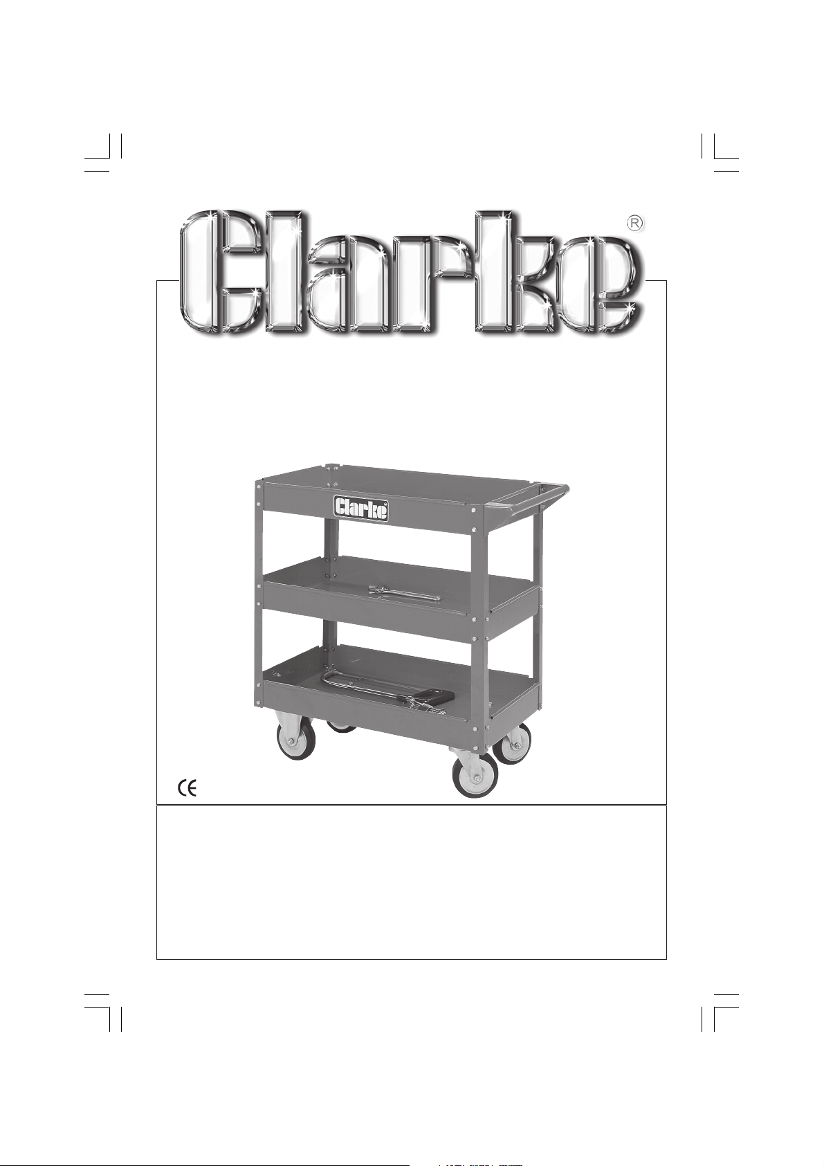
3 TIER TROLLEY
Model No: CTT5
ASSEMBLY
INSTRUCTIONS
Page 2

Thank you for purchasing this Clarke Three Tier Tool Trolley.
Before using this equipment, please read this instruction manual thoroughly. and
follow all directions carefully. By doing so, you will ensure the safety of yourself,
and others around you, and at the same time you should look forward to long
and trouble free service from your Clarke Three Tier Trolley.
Guarantee
This CLARKE product is guaranteed against faults in manufacture for 12 months
from purchase date. Please keep your receipt as proof of purchase.
This guarantee is invalid if the product has been abused or
tampered with in any way, or not used for the purpose for which it is intended.
The reason for return must be clearly stated.
This guarantee does not affect your statutory rights.
PARTS & SERVICE CONTACTS
For Spare Parts and Service, please contact your nearest dealer,
or CLARKE International, on one of the following numbers.
PARTS & SERVICE TEL: 020 8988 7400
PARTS & SERVICE FAX: 020 8558 3622
or e-mail as follows:
PARTS: [email protected]
SERVICE: [email protected]
Assembly Instructions
1. Locate the bottom tool tray - item 1 (which has holes to accommodate
the two castors and two fixed wheel assemblies).
2. Bolt the two castor assemblies - item 5, to the underside, and at one end
of the bottom tool tray, and the two fixed wheels (item 6) at the opposite
end, using the 16 nuts, bolts and washers supplied. Tighten nuts fully.
3. Bolt each of the corner supports - item 3, into place on the corners of the
bottom tool tray, using the nuts, bolts and washers supplied, leaving them
finger tight at this stage.
4. BoIt one of the remaining tool trays to the centre position, again, leaving
the nuts finger tight.
Page 3
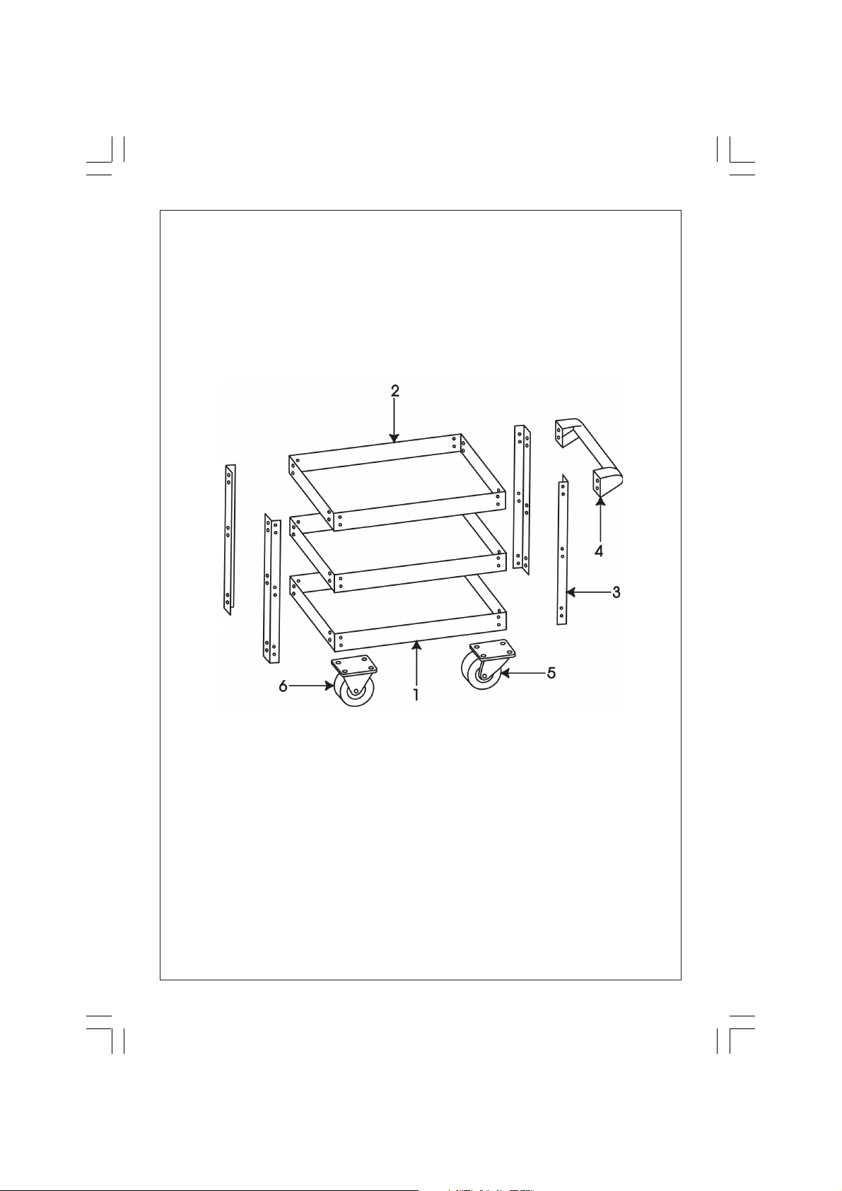
5. Bolt the top tool tray into place loosely leaving tour bolts from one end of
the tool tray - out, for the time being. (The same end to which the castors
are fitted to the bottom tray) These holes are used to mount the trolley
handle.
6. Gently move the assembly to and fro, to ensure that no part is under stress
and that it is not twisted in any way, and when satisfied, tighten all nuts
and bolts so far assembled
7. Bolt the Trolley Handle - item 4, to the end of the to p tool tray, using the
four vacant bolt holes, the bolts passing through the trolley handle, corner
support, and top tray. Tighten bolts, Your tool trolley is now ready for use.
Parts List
Item Description Qty Part No.
1 Bottom Tool tray 1 JA5001
2 Tool Tray
3 Corner Support 4 JA5003
4 Handle Assembly 1 JA5004
5 Castor Assembly 2 JA5005
6 Wheel Assembly 2 JA5006
Also supplied are 48 nuts, bolts and washers for securing the three
trays., and 16 sets for securing the four castor assemblies.
(top & centre) 2 JA5002
Page 4
 Loading...