

Page 1
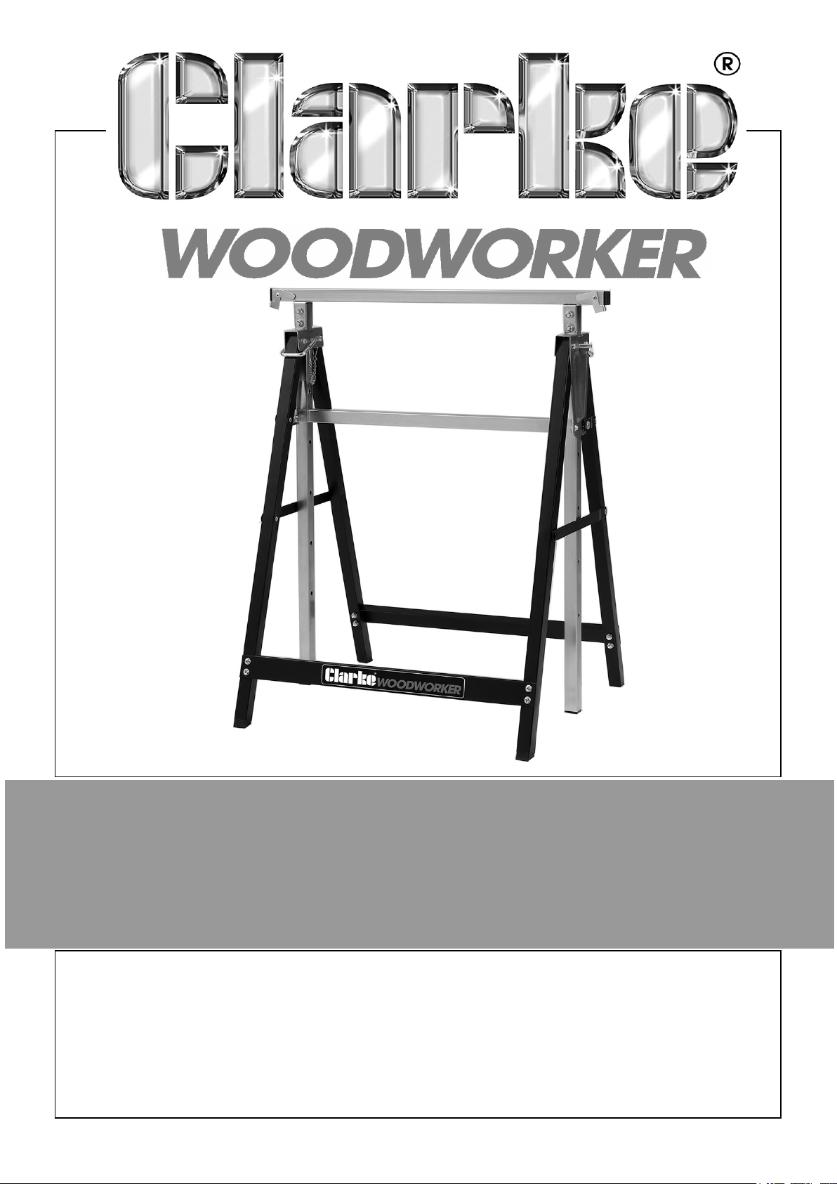
ADJUSTABLE TRESTLE
MODEL NO: CTA200
PART NO: 6600019
USER INSTRUCTIONS
ORIGINAL INSTRUCTIONS
GC0225
Page 2
INTRODUCTION
Thank you for selecting this CLARKE Adjustable Trestle. Before attempting to use it
please read this manual and carefully follow all instructions given. In doing so you will
ensure the safety of yourself and that of others around you. When opening the
packaging, lay out all the components to ensure all items are present and report any
deficiency to your CLARKE dealer.
SPECIFICATIONS
Dimensions D x W x H (mm) 180 x 690 x 800 (folded) - 1300 max height
Weight 5.8 kg
Maximum Load 200 kg
GUARANTEE
This product is guaranteed against faulty manufacture for a period of 12 months from
the date of purchase. Please keep your receipt which will be required as proof of
purchase.
This guarantee is invalid if the product is found to have been abused or tampered
with in any way, or not used for the purpose for which it was intended.
Faulty goods should be returned to their place of purchase, no product can be
returned to us without prior permission.
This guarantee does not effect your statutory rights.
SAFETY PRECAUTIONS
1. This trestle has a capacity of 200 kg which must not be exceeded.
2. DO NOT stand on the cross members or use as a step ladder. DO NOT stand on
top of the trestle.
3. DO NOT use the trestle as a scaffolding frame.
4. Take care when placing a load on the trestle. It should be placed gently so that
the strain is taken up gradually.
5. DO NOT mount power tools on the trestle.
6. ALWAYS check the trestle for damage before use.
7. ALWAYS ensure you are working on a firm, level surface.
8. ALWAYS make sure the locking pins are fully engaged before use.
2
Parts & Service: 020 8988 7400 / E-mail: [email protected] or [email protected]
Page 3
CONTENTS
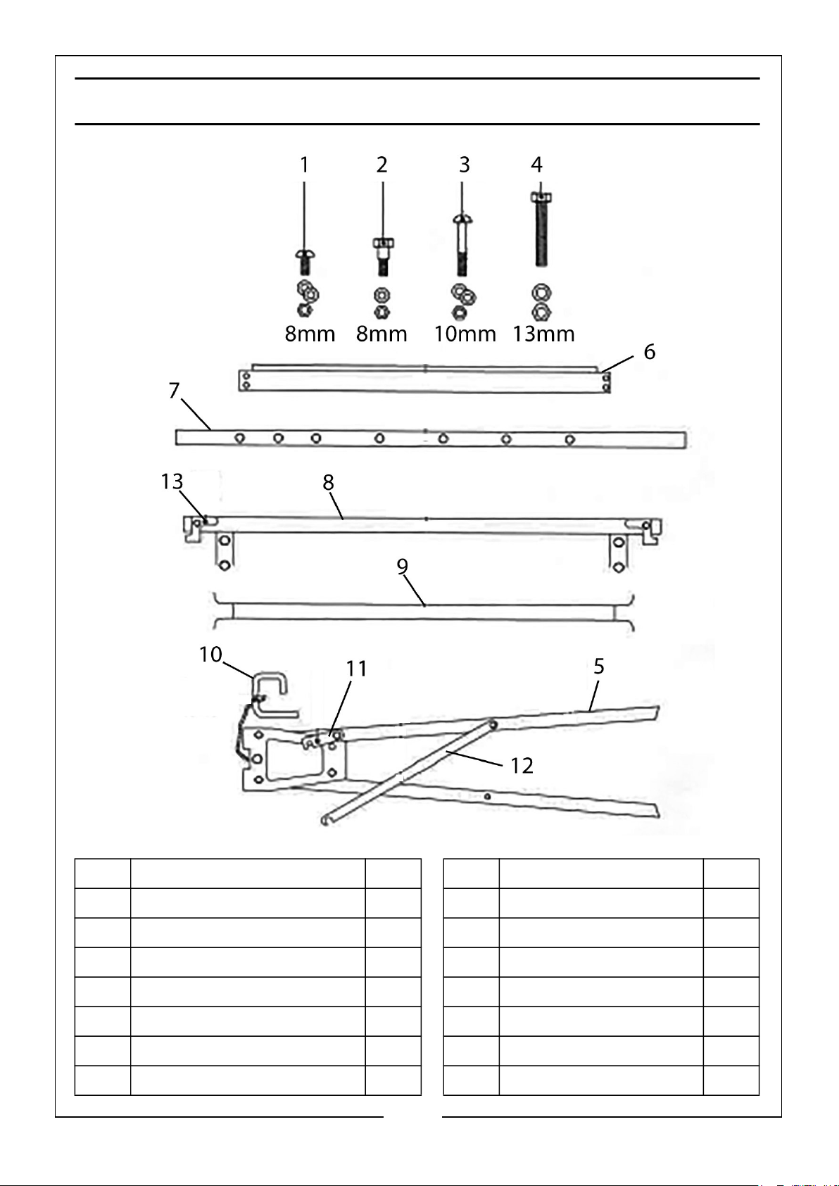
No Description Qty No Description Qty
1 Machine screw 8mm - short 2 8 Workpiece Support 1
2 Machine screw 8mm - long 2 9 Cross beam 1
3 Machine screw 10mm 8 10 Locking pin 2
4 Machine screw 13mm 4 11 Spreading lock-short 2
5 Side Frame 2 12 Spreader bar 2
6 Lower beam 2 13 Safety mount 2
7 Upright column 2
3
Parts & Service: 020 8988 7400 / E-mail: [email protected] or [email protected]
Page 4
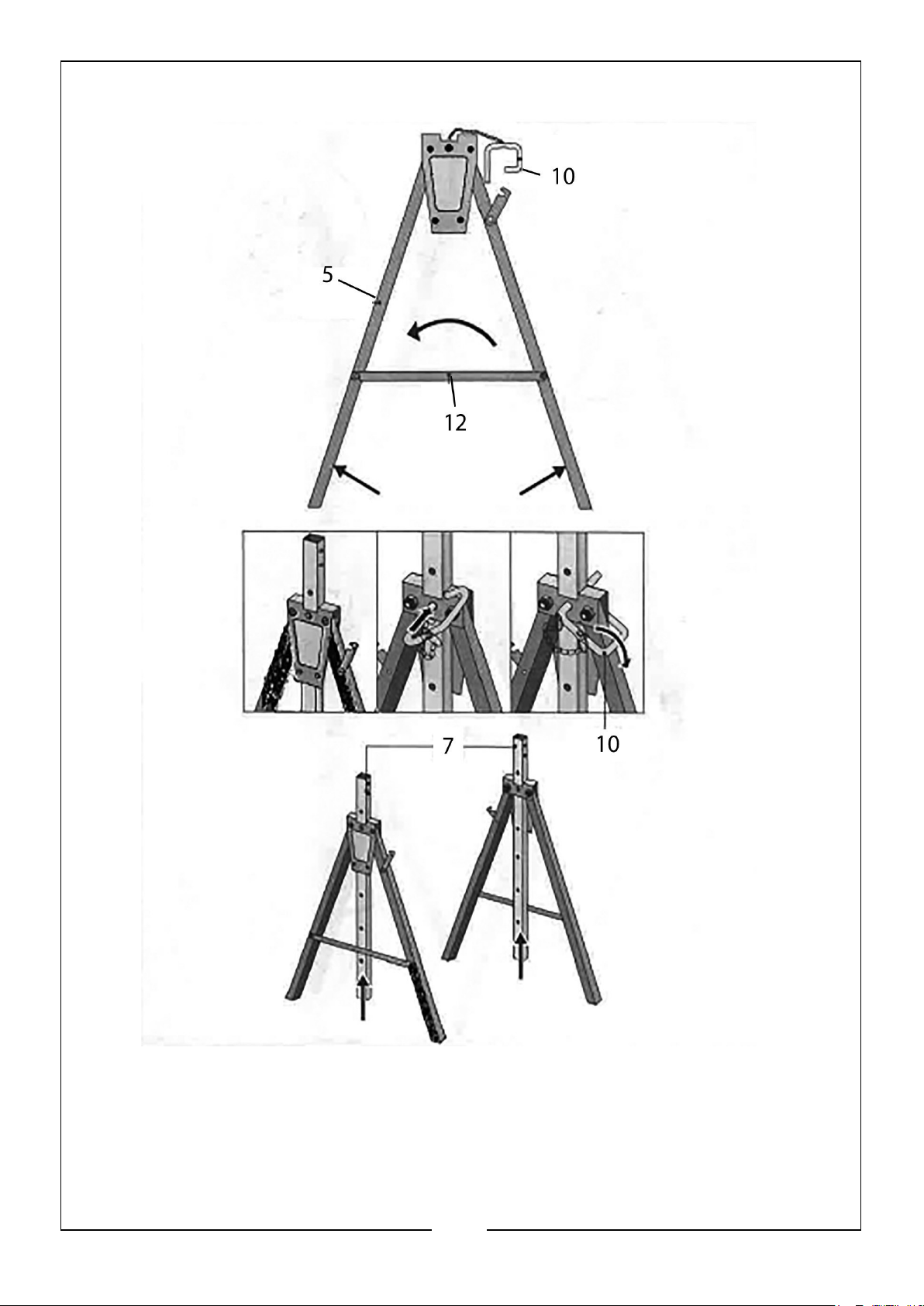
FIG 1
Open out the legs of each side frame (5) and lock them open with the spreader bar
(12). Raise the uprights (7) to an equal height and insert the locking pin (10) into
each frame to lock them in position.
4
Parts & Service: 020 8988 7400 / E-mail: [email protected] or [email protected]
Page 5
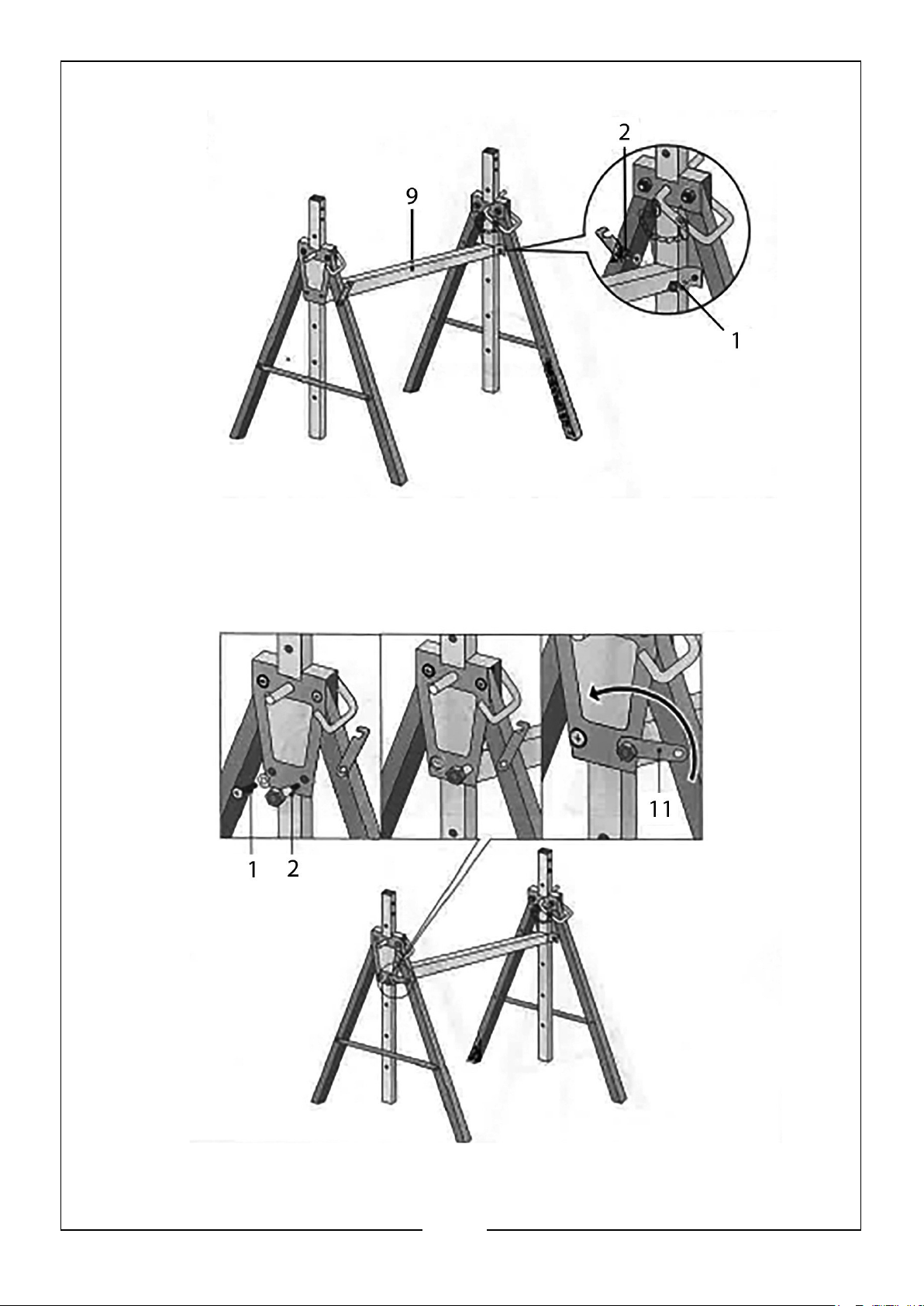
FIG 2
Add the cross beam (9) using 2 machine screws (1) and nuts at each end to secure it
to the end frames.
FIG 3
Add the hex shoulder bolts (2) with nuts and swing the locking tab into place to
engage with the shoulder bolt and secure the frames.
5
Parts & Service: 020 8988 7400 / E-mail: [email protected] or [email protected]
Page 6
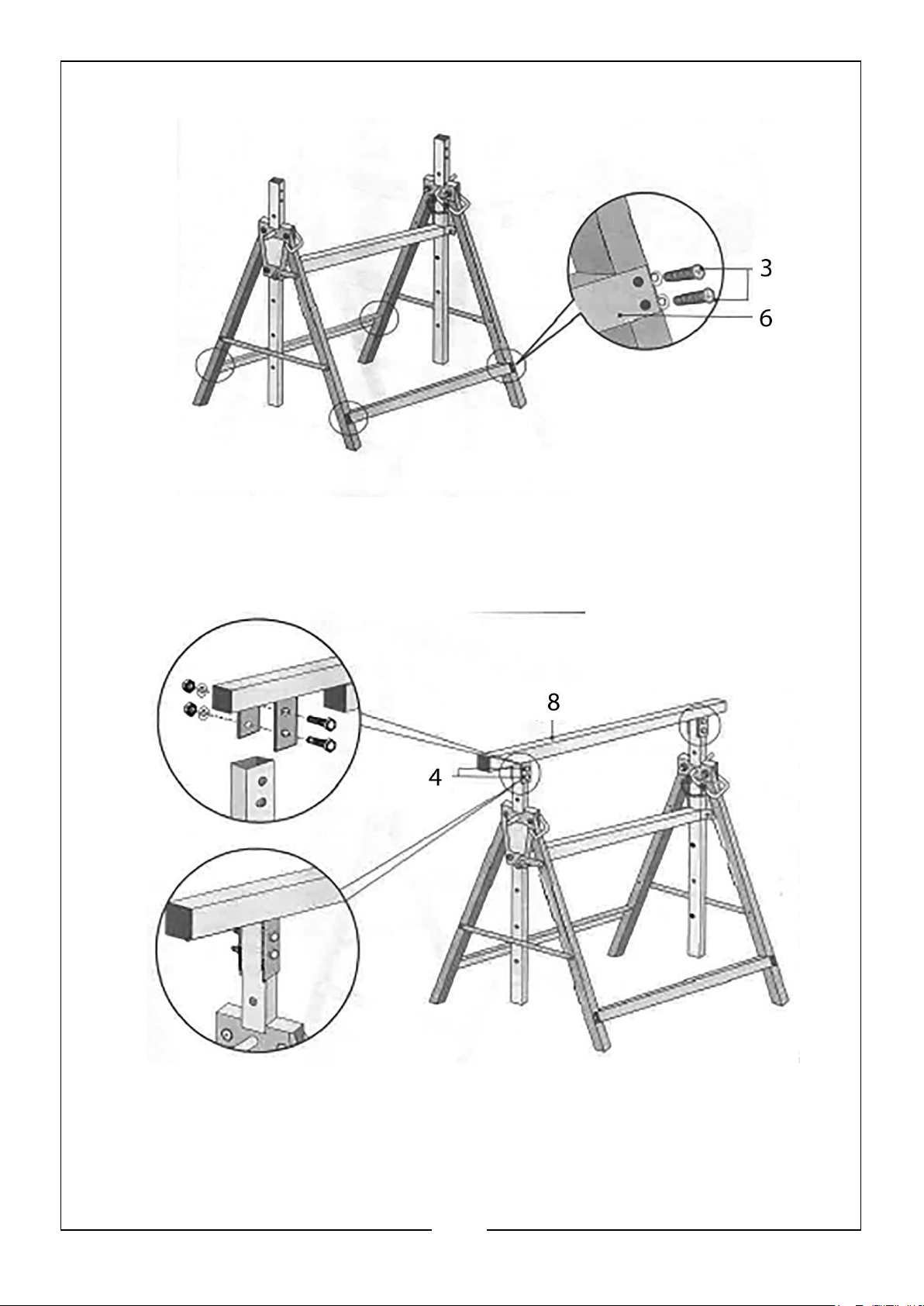
FIG 4
Add the two lower beams (6) and secure to the frames with the machine screws (3)
FIG 5
Add the workpiece support (8), fixing in place with the 2 x hex bolts (4) and nuts to
each of the trestle uprights.
6
Parts & Service: 020 8988 7400 / E-mail: [email protected] or [email protected]
Page 7
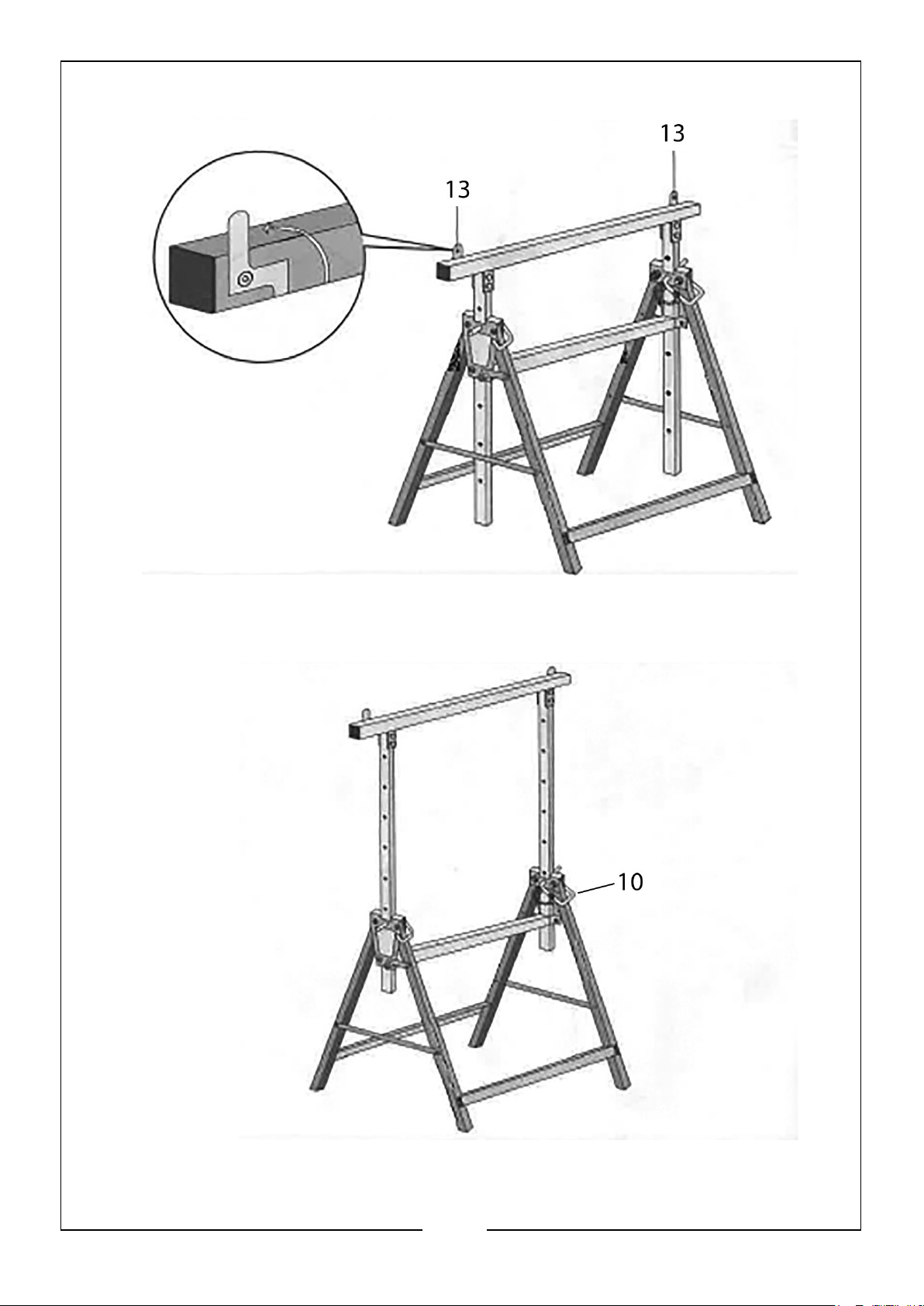
FIG 6
Hinge the retaining tabs (13) upright if required
FIG 7.
Finally raise the workpiece support beam to your required height and lock in place
using the locking pins (10).
7
Parts & Service: 020 8988 7400 / E-mail: [email protected] or [email protected]
Page 8

 Loading...