

Page 1

SPOT WELDER
SPOT WELDER
Models CSW6T & CSW13T
Part Nos. 6030005 & 60300010
OPERATING & MAINTENANCE
INSTRUCTIONS
0204
Page 2

© Copyright Clarke International. All rights reserved. October, 2001
2
Page 3

Thank you for purchasing this CLARKE Spot Welder.
Before attempting to operate this machine, please read this leaflet thoroughly
and follow the instructions carefully, in doing so you will ensure the safety of yourself
and that of others around you, and you can look forward to the welder giving
you long and satisfactory service.
GUARANTEE
This CLARKE product is guaranteed against faulty manufacture for a period of 12
months from the date of purchase. Please keep your receipt as proof of purchase.
This guarantee is invalid if the product is found to have been abused or tampered
with in any way, or not used for the purpose for which it was intended.
Faulty goods should be returned to their place of purchase, no product can be
returned to us without prior permission.
This guarantee does not effect your statutory rights.
CONTENTS PAGE
Electromagnetic Interference (EMC) ................................................4
Safety Precautions ...............................................................................6
Additional Safety Precautions for Spot Welding............................... 11
Features .................................................................................................. 7
Unpacking and Parts Identification ..................................................... 8
Assembly ................................................................................................ 9
Electrical Connections .......................................................................... 9
Preparation for Use - ............................................................................ 10
Operation ............................................................................................. 11
Maintenance ........................................................................................ 12
Accessories .......................................................................................... 13
Wiring Diagrams ................................................................................... 14
Spare Parts .................................................................................... 15 - 16
Specifications ....................................................................................... 17
Parts & Service Contacts ..................................................................... 17
Explanation of Electrical Symbols ...................................................... 19
3
Page 4

ELECTROMAGNETIC INTERFERENCE (EMC)
Whilst this unit complies with EMC regulations, the user is responsible for installing
and using the welding equipment according to the manufacturers instructions. If
electromagnetic disturbances are detected then it shall be the responsibility of
the user of the welding equipment to resolve the situation. In some cases this
remedial action may be as simple as earthing the welding circuit, see ‘Note’. In
other cases it could involve constructing an electromagnetic screen enclosing
the power source and the work complete with associated input filters. In all cases
electromagnetic disturbances must be reduced to the point where they are no
longer troublesome.
Note - The welding circuit may or may not be earthed for safety reasons. Changing
the earthing arrangements should only be authorised by a person who is
competent to assess whether the changes will increase the risk of injury, e.g. by
allowing parallel welding current return paths which may damage the earth circuits
of other equipment.
1.ASSESSMENT OF AREA
Before installing welding equipment the user shall make an assessment of potential
electromagnetic problems in the surrounding area. Avoid using your inverter in
the vicinity of:
a) other supply cables, control cables, signalling and telephone cables;
above, below and adjacent to the welding equipment;
b) radio and television transmitters and receivers;
c) computer and other control equipment;
d) safety critical equipment, e.g. guarding of industrial equipment;
e) pacemakers and hearing aids etc;
f) equipment used for calibration or measurement;
g) other equipment in the environment. The user shall ensure that other
equipment being used in the environment is compatible. This may
require additional protection measures;
It may be possible to avoid the above by changing the time of day that welding
or other activities are to be carried out.
The size of the surrounding area to be considered will depend on the structure of
the building and other activities that are taking place. The surrounding area may
extend beyond the boundaries of the premises.
2. METHODS OF REDUCING EMISSIONS
2.1 Mains supply
Welding equipment should be connected to the mains supply according to the
manufacturers recommendations. If interference occurs, it may be necessary to
4
Page 5

take additional precautions such as filtering of the mains supply. Consideration
should be given to shielding the supply cable of permanently installed welding
equipment, in metallic conduit or equivalent. Shielding should be electrically
continuous throughout its length. The shielding should be connected to the welding
power source so that good electrical contact is maintained between the conduit
and the welding power source enclosure.
2.2 Maintenance of the welding equipment
The welding equipment should be routinely maintained according to the
manufacturers recommendations. All access and service doors and covers should
be closed and properly fastened when the welding equipment is in operation.
The welding equipment should not be modified in any way except for those
changes and adjustments covered in the manufacturers
instructions. In particular, the spark gaps of arc striking and stabilizing devices should
be adjusted and maintained according to the manufacturers recommendations.
2.3 Equipotential bonding
Bonding of all metallic components in the welding installation and adjacent to it
should be considered. However, metallic components bonded to the work piece
will increase the risk that the operator could receive a shock by touching these
metallic components and the electrodes at the same time. The operator should
be insulated from all such bonded metallic components.
2.4 Earthing of the workpiece
Where the workpiece is not bonded to earth for electrical safety, nor connected
to earth because of its size and position, e.g. ships hull or building steelwork, a
connection bonding the workpiece to earth may reduce emissions in some, but
not all instances.
Care should be taken to prevent the earthing of the workpiece increasing the risk
of injury to users, or damage to other electrical equipment.
Where necessary, the connection of the workpiece to earth should be made by
a direct connection to the workpiece, but in some countries where direct
connection is not permitted, the bonding should be achieved by suitable
capacitance, selected according to national regulations.
2.5 Screening and shielding
Selective screening and shielding of other cables and equipment in the surrounding
area may alleviate problems of interference. Screening of the entire welding
installation may be considered for special applications.
5
Page 6

SAFETY PRECAUTIONS
ALWAYS
✔ Wear suitable safety goggles, manuf. to the latest European Safety Standards.
✔ Use appropriate safety equipment, such as protective footwear, overalls,
gloves etc., with NO metal accessories.
✔ Make sure there is adequate ventilation. Don’t weld in confined or en closed areas
✔ Switch off and disconnect the Spot welder from the mains supply when it is
not in use, and before any adjustment or maintenance.
✔ Comply with ALL instructions regarding Electrical Connections.
✔ Disconnect the machine from the power supply before servicing or performing
other maintenance tasks.
✔ Ensure the working area is clean and well lit. NEVER work in your own shadow.
✔ Use only original CLARKE spare parts and accessories. Improper accessories
could be hazardous.
✔ Keep proper footing and balance at all times.
✔ Keep children and visitors away from the machine. Only qualified personnel
should be authorised to use this machine.
✔ Maintain the machine in top condition. Keep it clean for best and safest performance.
✔ Keep the work area as childproof as possible by using padlocks and master switches.
✔ Switch machine OFF when changing/substituting fittings.
NEVER
✗ Use the Spot welder in wet or damp conditions or in the rain.
✗ Attempt any electrical or mechanical repairs yourself. Contact CLARKE
Service Department for advice.
✗ Place your hands close to the electrodes.
✗ Pull the plug from the power supply by the power cable.
✗ Use the machine in an area where fumes from paint, solvents, or flammable
liquids pose a potential hazard. Keep flammable material away from the
machine when operating. All flammable waste, such as cleaning rags etc.,
should be placed in a closed metal container and disposed of properly.
✗ Weld containers which have held liquid or gaseous combustibles unless they
have been cleaned thoroughly in accordance with COSHH regulations.
✗ Operate the machine while under the influence of drugs, alcohol or other medication.
✗ Force the machine to do a job for which it was not designed. Use it ONLY for
its’ intended function.
✗ Use machine if power cable is worn or chafed or suspect in any way.
✗ Allow inexperienced personnel to operate this machine unless they are under
direct supervision
6
Page 7

FEATURES
Model CSW6T
This 230V 50Hz, portable Spot Welder is provided with an electronic timer which
allows precise control of welding time. The control knob is arrowed in Fig. 1.
Electrode pressure may be mechanically adjusted from 40 to 120kg, to spot weld
low carbon sheet steel up to 1 + 1 mm in thickness.
Fig.1
Model CSW13T
The most important features of this 230V 50Hz Portable Spot Welder are controlled by a
microprocessor, managed from the control panel, shown in Fig. 2. These features are:
1. Welding time, set according to
the thickness of metal to be
welded.
2. Changing selection for Welding
thickness
3. Changing resistance welding
machine operating mode...
normal or pulse.
Selecting ‘PULSE’ mode improves
welding capacity on material
with high yield points or materials
with protective coatings. The
pulsation period is preset and
does nor require adjustment.
4. Electrode pressure may be mechanically adjusted from 40 to 120kg, to spot
weld low carbon sheet steel up to 2 + 2 mm in thickness.
Fig.2
Both Models
• 120mm Electrode Arms and standard electrodes are provided.
• An eye bolt may be fitted to the machine (see your Clarke dealer), for use in
supporting the machines weight when repetitive welds are required (see your
Clarke dealer). IMPORTANT! When using the Eye Bolt, Take care NOT to screw
it more than 8mm into the screw hole.
7
Page 8

UNPACKING & PARTS IDENTIFICATION
Unpack and lay out the components, checking against the following list. Please
report any damage which may have occurred during transit, to your CLARKE
dealer immediately.
1. Welder complete.
2. 1 x Handle - A
3 2 x Electrode Holders - B
4 2 x Electrodes (straight) - C
5. 2 x Hex. Wrenches - D
6. 1 x M6 Screw - F
Fig.3
Fig.4
1. Pressure Adjuster screw
2. Handle
3. Control panel (13T)
4. Electrode Arm
5. Electrode (Long)
6. Screw Locating Hole
7. Data Label
8. Microswitch
9. Weld Time Adjuster (6T)
10. Operating Lever
11. Spacer (Optional)
12. Lifting Eye (optional)
8
Page 9

ASSEMBLY
1. Screw the handle (2) into the threaded hole provided on either the left or
right hand side, as desired.
2. Insert the Electrode Arms, to their fullest extent, into their receptacles and nip
up the clamps using the Hex. wrench provided...do not fully tighten at this stage.
NOTE: Whenever removing and replacing the holders, ensure they, and the
receptacles, are clean and free from oil, grease or other contaminants.
3. Connect the machine to the electrical supply in accordance with IEE
regulations and the following instructions:
ELECTRICAL CONNECTIONS
Connect the mains lead, through a suitably fused isolator switch, to a 230 Volt
(50Hz) electrical supply, in accordance with IEE regulations and ensuring the fuse
rating is according to the specifications given on page 17. A standard 13 Amp
plug MUST NOT be used with this machine.
WARNING! THIS APPLIANCE MUST BE EARTHED
IMPORTANT: The wires in the mains lead are coloured in accordance with the
following code:
Green & Yellow - Earth
Blue - Neutral
Brown - Live
As the colours of the flexible lead of this appliance may not correspond with the
coloured markings identifying terminals in your electrical supply, proceed as follows:
• Connect GREEN & YELLOW cord to terminal marked with a letter “E” or Earth
symbol “ ” or coloured GREEN or GREEN & YELLOW.
• Connect BROWN cord to terminal marked with “L” or coloured RED.
• Connect BLUE cord to terminal marked with “N” or coloured BLACK.
WARNING!
IF YOU ARE IN ANY DOUBT ABOUT ELECTRICAL CONNECTIONS, CONSULT A
QUALIFIED ELECTRICIAN.
NEVER ATTEMPT ELECTRICAL REPAIRS YOURSELF.
Cable Extensions:
IMPORTANT:
For extensions up to 10M, the size of the conductors MUST be at least the same
size as that used on the machine - 2.5mm2. It is NOT advised to use extensions
greater than this, but if it is absolutely necessary, the conductor size must be
4mm2 up to a maximum of 25M in length.
9
Page 10

PREPARING THE WELDER FOR USE
WARNING!
ENSURE THE WELDER IS DISCONNECTED FROM THE SUPPLY, BEFORE PROCEEDING
1. Fit the Electrodes to the Electrode Arms. Whether or not the longer electrode is
located in the upper or lower arm, depends upon the work in hand. It may be
necessary for example to reach over a lip in a workpiece, necessitating the longer
electrode to be positioned in one particular arm. Normally however, the longer
electrode is located in the upper arm. Nip up the clamps but do not fully tighten.
2. Depress the operating lever fully, and insert
the M6 screw provided, into the threaded
hole, as shown in Fig.5.
Screw in fully so that the lever is held in the
fully down position as shown. This is the
position used for adjusting the electrode
gap.
3. Before setting the electrode gap however,
it is important to ensure that the electrode
arms are parallel to each other and the
electrodes are perfectly in line, on the
same axis, when the operating lever is fully depressed. This is achieved by slackening
the respective arm clamp and rotating the arms within the receptacle until the
electrodes meet exactly and are perfectly in line. When satisfied, tighten the clamps.
4. Slacken off the upper electrode clamp and move the electrode so that a piece of
material of the same total thickness as that to be welded, can be inserted between
the electrodes, then tighten the electrode clamp. The correct gap is now set.
5. Remove the M6 screw and release the lever.
6. Adjust the pressure to be exerted by
the electrodes by turning the adjuster
screw (item 1, Fig.4), using the Hex.
wrench provided, clockwise to
increase, anticlockwise to decrease,
according to the scale shown in Fig.6.
Fig.5
Fig.6
NOTE:
Always remember that too high a pressure will
result in damage to the electrode tips, whereas
too little pressure will result in a poor weld.
Pressure is also dependant upon the length of
electrode arms....the longer the arms the lighter the pressure setting. This must be taken into
account if/when replacing the electrode arms with any of those available from you Clarke
dealer, (see Accessories).
7. Set the welding time by either turning the dial adjuster, shown in Fig.1, (model 6T), or
pressing the button shown at 1 Fig. 2 (model 13T). Generally , the thicker the
workpiece, the longer the welding time.
10
Page 11

N
OTE:
The time scale shown on the control panel of the 13T, is a general guide only. It is advisable
to make a few test welds on material similar to the workpiece before commencing work,
making adjustments of pressure and welding time, as necessary, until a perfect weld is
achieved.
8. MODEL 13T only
8.1 Select the welding mode....normal or pulse, by pressing the appropriate
button on the control panel accordingly. (Button 3, Fig 2)
8.2 Select the welding thickness by pressing the appropriate button on the
control panel accordingly. (Button 2, Fig 2)
OPERATION
WARNING!
BE AWARE THAT THE MACHINE PRODUCES VERY INTENSE ELECTROMAGNETIC
FIELDS. THIS COULD SERIOUSLY EFFECT PEOPLE WEARING PACEMAKERS OR FITTED
WITH PROSTHESES. THESE PEOPLE SHOULD NOT BE ALLOWED TO USE THE MACHINE
OR BE IN ITS VICINITY.
MALFUNCTIONS OR DAMAGE TO WATCHES, MAGNETIC CARDS,
INSTRUMENTATION, DATA TRANSMISSIONS OR TELEPHONE RECEPTION COULD
ALSO OCCUR. THESE POINTS MUST ALWAYS BE TAKEN INTO CONSIDERATION WHEN
SITING THE WELDER
IMPORTANT!
1. Ensure the work surfaces are perfectly clean. There should be no rust or other
contaminants which would seriously impair the quality of the weld. Ideally,
the workpieces should be clamped together.
2. Ensure the electrode tips are correctly formed. They should be checked
regularly when welding to ensure they make perfect contact with the work.
A Spot Welding Tip dresser is available from your Clarke dealer, please call
for details.
• With the machine correctly adjusted, connect to the mains supply.
• Bring the lower electrode up to the work so that it is positioned directly beneath
the point to be welded.
• Depress the operating lever fully so that the microswitch is activated, and
hold in this position for a short period. Current to the electrodes will
automatically shut off after the welding time has been reached, at which
time you may withdraw the welder. A short delay, from the end of the weld
cycle to removing the electrodes, will improve the weld characteristics.
Should the welder not operate correctly, or a particularly poor weld is produced,
the following checks may determine the cause.
11
Page 12

a. Ensure the work is perfectly clean
b. Ensure the welding parameters are all correct.
c. Ensure the microswitch is actually pressed, and held for the duration of the weld.
d. Ensure the thermal overload has not been activated.
NOTE:
The
THERMAL OVERLOAD
operates when the electrical circuits have overheated. This
prevents the machine from operating until it has cooled
down to satisfactory levels. The device will operate if the
DUTY CYCLE has been exceeded or if the ambient
temperature becomes too high. NEVER EXCEED THE DUTY
CYCLE - See Specifications
On model 13T, if the thermal overload has intervened, the two lamps shown in Fig. 7 will
flash alternately.
is a protection device which
Fig.7
MAINTENANCE
WARNING!
ELECTRICITY CAN KILL
NEVER TOUCH LIVE ELECTRICAL COMPONENTS
DISCONNECT THE POWER SUPPLY BEFORE ALL INSPECTIONS AND
MAINTENANCE OPERATIONS
BEWARE HOT SURFACES.....ALWAYS LET THE POWER SUPPLY COOL DOWN
BEFORE ACCESSING INTERNAL COMPONENTS.
Frequency of maintenance operations depends on the operating conditions: how
intensively the welder is used, how clean or dirty the welding site is (aggressive
atmospheres, etc).
Before use, always inspect the welder, checking for security and cleanliness of
arms and electrodes, to ensure they are in perfect condition. Ensure also that the
power cable is in perfect condition at all times.
As a general rule the power supply should be inspected internally at least twice a year.
1. Access the inside of the machine by removing the screws securing the side
cover and carefully hinge the cover down.
2. Clean the transformer using a blast of dry compressed air with a maximum
pressure of 10bar. NEVER direct the compressed air jet on to the circuit
boards. These should be cleaned with a soft brush and vacuumed or blown
with air at very low pressure. ALWAYS use a face mask for these operations.
3. Check all wiring for insulation damage or loose or oxidised connections.
Repair/replace where necessary. Check all screws and connections are
tight and there are no signs of oxidation or overheating.
4. Replace the cover.
WARNING! NEVER CONNECT THE MACHINE UNLESS THE COVER IS REPLACED
12
Page 13

ACCESSORIES
The following accessories are available from your Clarke dealer.
Description Throat Part No.
Electrodes ‘L’ 120mm 6030105
Electrodes ‘L’ 250mm 6030107
Electrodes ‘L’ 500mm 6030109
External Profile - 6030111
Electrodes
Internal Profile - 6030113
Electrodes
Electrodes 120mm 6030115
Electrodes 350mm 6030117
Electrodes 350mm 6030119
Electrodes 120mm 6030121
Lifting Eye ................................................ See your Clarke dealer
Electrode Tip Dressing Tool .................... See your Clarke Dealer
13
Page 14

SCHEMATIC WIRING DIAGRAMS
CSW6T
CSW13T
14
Page 15
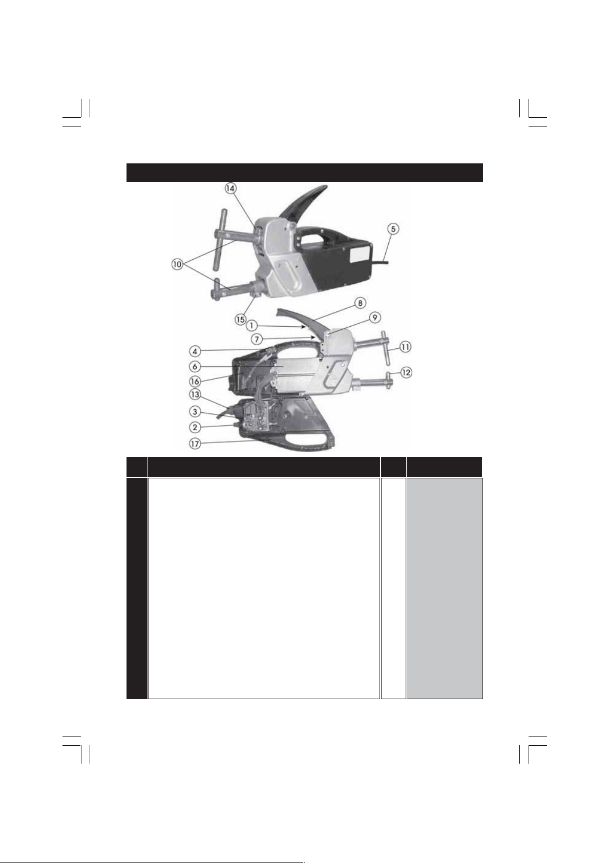
SPARE PARTS - CSW6T
No. Description No. Part Number
Bush 1 TT322518
1
2 Potentiometer (Adjuster) Knob 1 TT112299
3 Timer PCB 1 TT114236
4 Microswitch 1 TT122393
5 Mains Cable 1 TT132104
6 Transformer 1 TT169152
7 Adjuster Screw 1 TT121263
8 Operating Lever 1 TT322512
9 Pivot Pin 1 TT482887
10 See Page 13 for full range of Arms
11 See Page 13 for full range of Electrodes
12 See Page 13 for full range of Electrodes
13 Cable Kit - Bushing, Ring Nut 1 TT990046
14 Upper Arm Clamp 1 TT522020
15 Lower Arm Clamp 1 TT522023
16 Left Shell 1 TT322509
17 Right Shell 1 TT322526
15
Page 16

SPARE PARTS - CSW13T
No. Description No. Part Number
1 Screw 1 TT113908
2 Control PCB 1 TT114070
3 Power PCB 1 TT114085
4 Microswitch 1 TT122393
5 Mains Cable 1 TT132104
6 Transformer 1 TT169034
10 Cable Kit - Bushing, Ring Nut 1 TT990046
11 Pivot Pin 1 TT482887
12 Operating Lever 1 TT322512
13 Adjuster Screw 1 TT212163
14 Upper Arm Clamp 1 TT522020
15 Lower Arm Clamp 1 TT522023
16 Right Shell 1 TT322510
17 Left Shell 1 TT322511
16
Page 17

SPECIFICATIONS
CWS6T CWS13T
Power Supply ................................... 230V 50Hz 1Ph .............. 230V 50Hz 1Ph
Max Absorbed Power ..................... 6kW ................................ 13kW
Power Rating .................................... 1.2kW ............................. 2.3kW
Mains Fuse ....................................... 16Amp ........................... 25Amp
Spot Welding Current (Max) .......... 3800Amps ..................... 6300Amps
Duty Cycle ....................................... 3 spots/min. with minimum down time of 20 secs.
Max. Welding Thickness ................. 1+1mm .......................... 2+2mm
Dimensions (mm) ............................ 440x110x185 ................. 440x110x185
Weight .............................................. 10.5kg ............................ 11kg
Please note that the details and specifications contained herein, are correct at the time of going to
print. However, CLARKE International reserve the right to change specifications at any time without
prior notice. Always consult the machine’s data plate
SPARE PARTS AND SERVICE CONTACTS
For Spare Parts and Service, please contact your nearest dealer, or
CLARKE International, on one of the following numbers.
PARTS & SERVICE TEL: 020 8988 7400
PARTS & SERVICE FAX: 020 8558 3622
or e-mail as follows:
PARTS: [email protected]
SERVICE: [email protected]
17
Page 18

EXPLANATION OF ELECTRICAL SYMBOLS
The meaning of the markings and symbols shown in the table are explained
as follows.
50Hz
I
2cc
A
I
2
1
Rated frequency for alternating current
Short Circuit Secondary Current
Symbol and dimension for the welding current
Rated value of the supply voltage
IP_ _ Degree of protection (e.g. IP21)
S max Max. Absorbed Power
U 20
F max
No Load Secondary Voltage
Electrode max. strength
19
 Loading...