

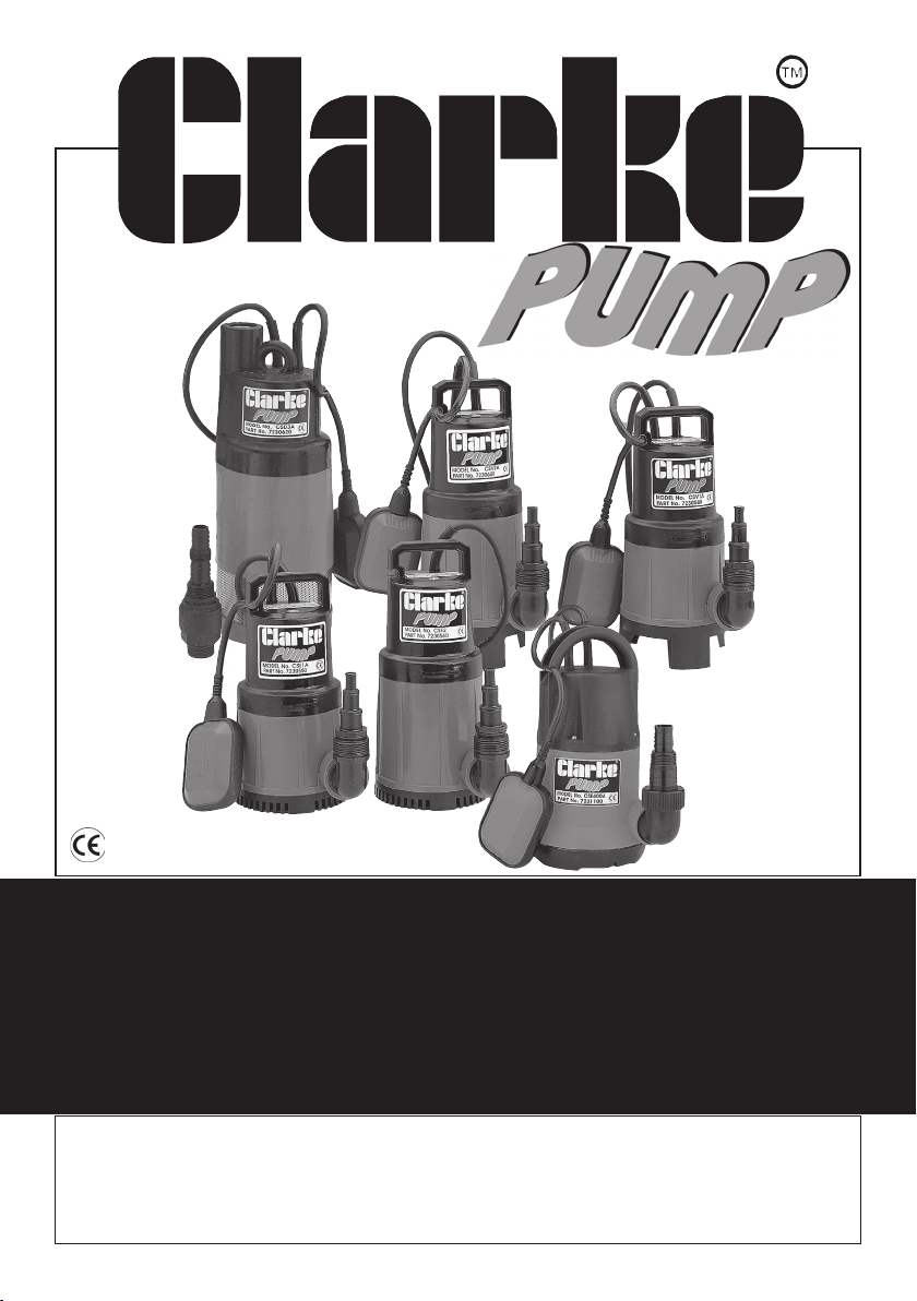
SUBMERSIBLE WATER PUMP
Model Nos.
CSE1 - CSE1A - CSE2 - CSE2A
CSD3- -CSD3A
CSV1A - CSV2 - CSV2A - CSW1A
OPERATING & MAINTENANCE
INSTRUCTIONS
1117
GUARANTEE
This product is guaranteed against faults in manufacture for 12 months
from purchase date. Please keep your receipt as proof of purchase.
This guarantee is invalid if the product has been abused or tampered
with in any way, or not used for the purpose for which it is intended.
The reason for return must be clearly stated.
This guarantee does not affect your statutory rights.
Please note that dismantling this pump will invalidate the guarantee
SPECIFICATIONS
Model No. CSE1 CSE2 CSV1A CSV2 CSD3
CSE1A CSE2A CSV2A CSD3A
CSW1
Outlet Dia. 1¼”/32mm 1¼”/32mm 1¼”/32mm 1¼”/32mm 1”/25mm
Motor Output (Watts) 280 750 330 650 1100
Head Max. (M) 7 10 5 9 45
Max. Capacity (L/min) 135 253 118 236 95
Weight (kg) 4.0/4.3 4.3/4.6 4.6 5.3/5.6 8.0/8.3
Cable (Mxmm2) 10x1.25 10x1.25 10x1.25 10x1.25 10x1.25
Dimensions (mm)* 140x267 140x302 143x300 143x335 149x400
* Pump diameter does not include elbow
Part Numbers.
CSE1 7230540 CSE2A* 7230570 CSV2A* 7230600
CSE1A* 7230550 CSV1A* 7230580 CSD3 7230610
CSE2 7230560 CSV2 7230590 CSD3A* 7230620
CSW1A* 7236005
*Denotes Float Switch included
ENVIROMENTAL RECYCLING POLICY
Through purchase of this product, the customer is taking on the
obligation to deal with the WEEE in accordance with the WEEE
regulations in relation to the treatment, recycling & recovery and
environmentally sound disposal of the WEEE.
In effect, this means that this product must not be disposed of with general
household waste. It must be disposed of according to the laws governing
Waste Electrical and Electronic Equipment (WEEE) at a recognised disposal
facility.

Thank you for purchasing this Clarke Submersible Pump.
These highly efficient pumps are designed for pumping clean water, or water
containing sand or solids in suspension, depending upon the model (please see
Features, page 4), and are ideally suited for draining ponds, pools, building
excavations etc.Water temperature must not exceed 35° C.
Before attempting to operate your pump, please read this instruction manual thoroughly
and follow all directions carefully. This is for your own safety and that of others around
you, and to help you achieve long and trouble free service from your pump.
SAFETY PRECAUTIONS
1. These pumps are designed to pump WATER ONLY. Never use for pumping
flammable liquids or chemicals.
2. Never run the pump dry.
3. An approved Residual Current Device (RCD) MUST be used when pumping
from ponds or swimming pools.
4. Your submersible pump may ONLY be used for pumping water from a swimming
pool when there is no person or animal in the pool.
5. Always disconnect the pump from the electrical supplybefore placing it into,
or removing it from the water, and before any cleaning or maintenance of the
pump.
6. Always use the moulded handle (or lifting eye), with a rope or cord attached
when lifting the pump. NEVER lift the pump by the mains cable, or, where
fitted, the float switch cable.
7. DO NOT run the pump with the body exposed for longer than 10 minutes.
8. DO NOT install the pump on sand, or ground which is likely to shift.
9. Do not use the pump if the water is liable to freeze, as this can cause damage
to the pump. Remove the pump from the water and store it in a frost
free location.
10. If the pump is to be used where there may be silt or mud (for
example, garden ponds), keep the pump clear of any sediment by standing
it on a platform or brick.
WARNING
The water being pumped will be polluted if this pump becomes damaged
and lubricant within the pump escapes.
2

ELECTRICAL CONNECTIONS
All models should have their mains lead connected to a standard 230Volt (50Hz)
electrical supply through an approved plug or a suitably fused isolator switch. We
recommend that these pumps be fitted with a Residual Current Device (RCD).
NOTE: This is mandatory when pump is used for pumping swimming pools and ponds
If the pump is to be connected to an outdoor electrical supply, make sure that
both the plug and the socket are of a BS approved waterproof design.
In the event that the pump is hard wired into the electrical system, it must be
carried out in accordance with IEE regulations.
If used for draining swimming pools or ponds, the pump MUST be fitted with a Residual
Current Device (RCD), with a rated residual operating current of no greater than 30mA.
WARNING: THIS APPLIANCE MUST BE EARTHED
IMPORTANT: The wires in the mains lead are coloured in accordance with the
following code:
Green & Yellow - Earth
Blue - Neutral
Brown - Live
As the colours of the flexible cord of this appliance may not correspond with the
coloured markings identifying terminals in your plug proceed as follows:
• Connect GREEN & YELLOW cord to plug terminal marked with a letter “E” or
Earth symbol “ ” or coloured GREEN or GREEN & YELLOW.
• Connect BROWN cord to plug terminal marked with a letter “L” or coloured RED
• Connect BLUE cord to plug terminal marked with a letter “N” or coloured BLACK
FUSE RATING
The fuse in the plug must be replaced with one of the same rating (13 amps)
and this replacement must be ASTA approved to BS1362.
If this appliance is fitted with a plug which is moulded onto the electric cable (i.e.
non-rewirable) please note:
1. The plug must be thrown away if it is cut from the electric cable. There is a
danger of electric shock if it is subsequently inserted into a socket outlet.
2. Never use the plug without the fuse cover fitted.
3. Should you wish to replace a detachable fuse carrier, ensure that the correct
replacement is used (as indicated by marking or colour code).
4. Replacement fuse covers can be obtained from your local dealer or most
electrical outlets
IMPORTANT:
If you are in any doubt regarding electrical installation,
you should consult a qualified electrician.
3

FEATURES
The pumps are of rugged and durable construction, designed for long lasting
continuous operation, and the motor is provided with a built in overload protector.
For your information, the charts on page 8 illustrate the flow rate at various heads
for each pump. (HEAD is the distance, or height, from the pump outlet to the
point of discharge)
The pumps are designed to pump water at various degrees of cleanliness
depending upon the model as follows:
CSE Models are designed for pumping CLEAN WATER ONLY and will pump
down to a water level of 5mm.
CSV Models may pump DIRTY WATER:
That is, water containing solids in suspension, NOT for pumping slurry, sludge, mud
or heavily polluted water. These models have the ability to pump solids as large as
30mm, however, the outlet elbow and delivery pipe diameter will restrict this
accordingly (see outlet adapters - Installation, page 5).
CSD Models may pump DIRTY WATER with restrictions as with CSV pumps, and are
provided with a metal strainer to prevent large particles from entering the pump.
These are multi stage pumps, and are designed to work at greater heads up to 45 Metres.
CSW Models are salt water pumps for pumping CLEAN, salt water.
Automatic Pumps, i.e. those fitted with a Float Switch, denoted by an ‘A’ suffix to
their model number, are suitable for permanent or semi-permanent installations,
eg. installations where it is necessary to maintain a water at a particular level.
As the water level rises, the switch will float, and start the pump. As the water level
falls, so will the float switch, until it stops the pump.
Float switches are factory set to provide the correct ON-OFF switching mode,
however, you can adjust the level at which the pump cuts out by sliding the float
switch cable, in its clip attached to the handle, to either shorten or lengthen it as
the case may be. The shorter it is, the earlier it will cut out and therefore, the
deeper will be the water at this point.
4

INSTALLATION
The CSE, CSV and CSW Models are provided with an
Elbow Outlet with a 1-1/4”BSP thread at each end as
shown in the diagram opposite. Ensure the end
provided with an O-Ring is screwed into the pump
outlet. Screwed into the other end of the elbow, is a
multi hose connector capable of accepting 1”, 3/4”
0r 1/2” hose. Simply attach a suitable hose to your
preferred connector with a worm drive clip.
If the pump is to be used for drainage purposes, or in
situations that demand maximum efficiency, we strongly
recommend that you connect a 1” dia. hose to the multi hose adapter, preferably cutting
off the other two stages at the groove at the end of the 1” dia. step.
Alternatively, you may remove the multi adapter altogether, and screw on a 1-1/
4” BSP hose adapter as shown in fig.2.
The CSD Models are provided with a Multi Hose Adapter
for the outlet, which screws into the top of the unit, and
is illustrated in Fig. 1.
If you wish to use a 1”BSP hose adapter, cut the
multi hose adapter at point A.
If you wish to use a 3/4”BSP hose adapter, cut the
multi hose adapter at point C.
If you wish to connect a 1” hose, cut the multi hose adapter at point B, and finally,
if you wish to use a 3/4” hose, simply attach it to the end of the multi hose adapter
(point D), with a suitable worm drive clip.
We strongly recommend that you connect the outlet to the 1” diameter hose, as
any restrictions will reduce capacity, and put additional strain on the motor.
NOTE:
Please bear in mind that a hose adapter requires the use
of a rubber washer, as shown in fig 2, and the point at
which the multi hose adapter is cut (points A and C, fig. 1),
must be perfectly clean and square.
The pumps are completely submersible, and should be placed in a vertical position,
on a solid flat surface. If this is not available, sit the pump a solid surface, eg.
house bricks, but ensure they are not likely to shift.
IMPORTANT:
ALWAYS raise and lower the pump using a rope attached to the lifting eye,
where fitted, or to the lifting handle, NEVER by the power cable.
Automatic versions should be placed in a sump which has adequate dimensions
so as not to restrict the movement of the float switch.
Please note that the symbol
MAXIMUM depth to which the pump may be submerged, in metres.
on the pumps’ Rating Plate, denotes the
5

Take all necessary precautions as described on page 2 before plugging in, and
switching ON.
SUITABLE HOSE, and SPARE/REPLACEMENT MULTI HOSE ADAPTERS ARE AVAILABLE
FROM YOUR CLARKE DEALER
MAINTENANCE
WARNING
Before checking the condition of the pump, ensure it is unplugged from the
mains supply. If the unit is hard wired, ensure the circuit breaker is open.
Check the pump installation regularly to ensure the base inlet is clear of leaves or
other debris.
Note that these pumps are fitted with automatic thermal overload protection. If the
pump overheats due to an obstruction in the pump, or pumping warm water for example,
it will shut off automatically. Switch the pump OFF and disconnect from the mains supply.
Check for blockages and allow the motor to cool (at least 5 minutes) before attempting
to re-start.
These pumps should require no maintenance other than regular cleaning. If the pump
starts to show signs of wear or damage, contact your CLARKE dealer for advice. Do not
use the pump if there is any damage to the mains supply cable, or to the float switch or
its cable. Do not attempt to repair the pump yourself, as you may damage the waterproof
seal and invalidate your guarantee. Repairs must be carried out by your CLARKE dealer,
or contact the CLARKE Service Department, on 020 8988 7400
CSD Models are provided with a stainless
Notch
steel strainer which may be removed and
cleaned by removing the eight screws
securing it to the base.
Cover Pump Base
In addition, CSD models are provided with
a rubber plug in its’ base, which, when
removed, allows access to the impeller,
which may be turned with a screwdriver in
order to free it, should it become blocked.
Release Clips
CSE & CSW Models have screwless fittings at their base, allowing the removal of
the plastic cover by prising the two release clips apart in the direction of the arrows.
This provides for better cleaning, should the cavity at the
bottom of the pump become badly clogged. Flush the cavity
and the Impeller housing with clean water
To replace the cover, ensure the notch in its periphery
engages with the extended lug on one of the clip
attachments on the base of the pump, (as shown in
the diagram opposite), and press the cover home.
Do not attempt to strip the pump further as this will
invalidate the guarantee
6
Extended Lug

TROUBLE SHOOTING
A. PUMP WILL NOT START
1. Manual type (i.e. without float switch)
1.1 Check to ensure Power is switched on.
1.2 Check fuse (consult an electrician if in doubt).
1.3 If extension lead is fitted, check connections (consult an electrician if in
doubt).
1.4 Internal thermal cut-out has not re-set. Leave for 5 minutes and try again.
1.5 The Impeller may be jammed. Disconnect from the mains supply, remove
the bottom strainer, and remove any objects that may be obstructing
the impeller. Replace the strainer and try again.
If the pump still fails to start, consult your CLARKE dealer for advice.
2. Automatic Type (with float switch)
2.1 Check all above.
2.2 Float switch may be jammed against side wall, or prevented from moving.
2.3 Water level too low - float switch in OFF position - Lift float to check switch.
B. PUMP WILL START BUT NOT PUMP
1. Water level too low - below the minimum suction level (Manual type).
2. Check to ensure strainer is not blocked.
3. Discharge tube clogged or obstructed.
4. The head may be too great, i.e. you are trying to lift the water too great a
distance for the pump to cope with. (See specification chart page 9).
5. Air bubble in the pump, produced during the plunge. Plunge the pump
again, at an angle, and shake it whilst lowering to remove any air trapped
in the system.
6. Impeller may be damaged - Consult your CLARKE dealer
C. AUTOMATIC PUMP WILL NOT STOP
1. Float switch may be prevented from moving to the fully down position.
2. Float switch may be faulty. Consult your CLARKE dealer for advice.
D. PUMP STOPS RUNNING
1. Thermal overload has operated. If this condition persists, investigate the
cause. Are you attempting to pump liquid which is too heavy for the pump
(mud, slurry etc.)
2. Pump has run dry, or float switch has cut in.
3. A foreign object has jammed the impeller.
7

PUMP PERFORMANCE DATA
CSE 1 and 1A
CSV 1A
CSE 2 and 2A
CSE & CSW Pumps
CSV 2 and 2A
CSV Pumps
CSD 3 and 3A
8
CSD Pumps

9

PARTS LIST
No. Description CSW1 CSE1 CSE2
1 Floatswitch LDP1380033 LDP1380002 LDP1380002
2 Cap (Auto version) LDS3600170 LDS3600170 LDS3600170
2 Cap - LDS3600169 LDS3600169
3 Cable 10m LDP1320031 LDP1320016 LDP1320016
4 Grommet LDP1230002 LDP1230002 LDP1230002
5 Grommet LDP1230003 LDP1230003 LDP1230003
6 Capacitor LDP1360030 LDP1360030 LDP1360030
7 Lock LDS3500011 LDS3500011 LDS3500011
8 Anti-tear ring LDS3500336 LDS3500336 LDS3500336
9 Cable fastener LDS3500335 LDS3500335 LDS3500335
10 Screw LDP1100008 LDP1100008 LDP1100008
11 Earth screw LDP1100003 LDP1100003 LDP1100003
12 Spring-washer LDP1120003 LDP1120003 LDP1120003
13 Washer LDP1120051 LDP1120051 LDP1120051
14 Insulation disk LDS3500106 LDS3500106 LDS3500106
15 Upper flange LDS3120005 LDS3120005 LDS3120005
16 Waved-ring LDP1120002 LDP1120002 LDP1120002
17 Ceramic shaft w/bearings LDS3101018 LDS3101001 LDS3101002
18 Bearing LDP1180001 LDP1180001 LDP1180001
19 Washer LDP1120007 LDP1120007 LDP1120007
20 Lip seal LDP1210010 LDP1210001 LDP1210001
21 Stator LDS3410174 LDS3410003 LDS3410017
22 Joint O-Ring LDP1200007 LDP1200007 LDP1200007
23 Pump housing LDS3600348 LDS3600073 LDS3600075
24 Joint O-Ring LDP1200009 LDP1200009 LDP1200009
25 Elbow with O-Ring LDS3600111 LDS3600111 LDS3600111
26 Washer LDP1120006 LDP1120006 LDP1120006
27 Nut LDP1110025 LDP1110005 LDP1110005
28 Impeller LDS3500528 LDS3500528 LDS3500559
29 Joint O-Ring LDP1200008 LDP1200008 LDP1200008
30 Filter LDS3500017 LDS3500017 LDS3500017
31 Filter base LDS3500107 LDS3500107 LDS3500107
32 Joint O-Ring LDP1200033 LDP1200033 LDP1200033
33 Screw LDP1100090 LDP1100090 LDP1100090
34 Screw LDP1100014 LDP1100014 LDP1100014
35 Washer LDP1120017 LDP1120017 LDP1120017
36 Sphere LDP1180003 LDP1180003 LDP1180003
37 Twin lip seal LDP1210011 LDP1210004 LDP1210004
38 Joint -.Ring LDP1200002 LDP1200002 LDP1200002
39 Fitting 3 step with O-Ring LDS3600162 LDS3600162 LDS3600162
‘V’ Ring joint LDP1210002 LDP1210002 LDP1210002
40
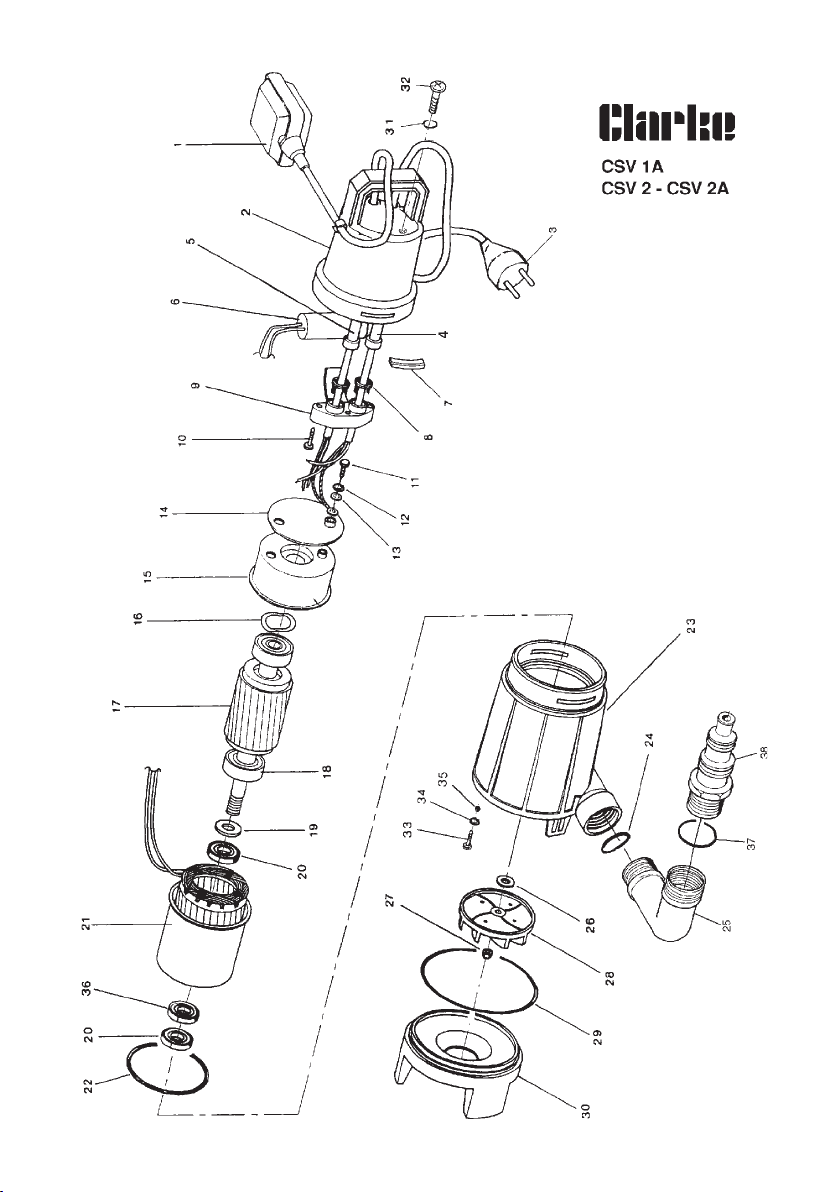

PARTS LIST
No. Description CLDSV1A CLDSV2 CLDSV2A
1 Floatswitch LDP1380002 - LDP1380002
2 Cap LDS3600170 LDS3600169 LDS3600170
3 Cable 10m. LDP1320016 LDP1320016 LDP1320016
4 Grommet - LDP1230002 -
5 Grommet LDP1230003 - LDP1230003
6 Capacitor LDP1360030 LDP1360030 LDP1360030
7 Lock LDS3500011 LDS3500011 LDS3500011
8 Anti-tear ring LDS3500336 LDS3500336 LDS3500336
9 Cable fastener LDS3500335 LDS3500335 LDS3500335
10 Screw LDP1100008 LDP1100008 LDP1100008
11 Earth screw LDP1100003 LDP1100003 LDP1100003
12 Spring-washer LDP1120003 LDP1120003 LDP1120003
13 Washer LDP1120051 LDP1120051 LDP1120051
14 Insulation disk LDS3500106 LDS3500106 LDS3500106
15 Upper flange LDS3120005 LDS3120005 LDS3120005
16 Waved ring LDP1120002 LDP1120002 LDP1120002
17 Ceramiic shaft with bearings LDS3101001 LDS3101002 LDS3101002
18 Bearing LDP1180001 LDP1180001 LDP1180001
19 Washer LDP1120007 LDP1120007 LDP1120007
20 Lip seal LDP1210001 LDP1210001 LDP1210001
21 Stator LDS3410004 LDS3410017 LDS3410017
22 Joint O-Ring LDP1200007 LDP1200007 LDP1200007
23 Pump housing LDS3500206 LDS3500207 LDS3500207
24 Joint O-Ring LDP1200009 LDP1200009 LDP1200009
25 Elbow with O-Ring LDS3600111 LDS3600111 LDS3600111
26 Washer LDP1120006 LDP1120006 LDP1120006
27 Nut LDP1110005 LDP1110005 LDP1110005
28 Impeller LDS3500013 LDS3500014 LDS3500014
29 Joint O-Ring LDP1200008 LDP1200008 LDP1200008
30 Pedestal LDS3500018 LDS3500018 LDS3500018
31 Joint O-Ring LDP1200033 LDP1200033 LDP1200033
32 Screw LDP1100090 LDP1100090 LDP1100090
33 Screw LDP1100014 LDP1100014 LDP1100014
34 Washer LDP1120017 LDP1120017 LDP1120017
35 Sphere LDP1180003 LDP1180003 LDP1180003
36 Twin lip seal LDP1210004 LDP1210004 LDP1210004
37 Joint O-Ring LDP1200002 LDP1200002 LDP1200002
38 Fitting 3 step with O-Ring LDS3600162 LDS3600162 LDS3600162

CSD3 & CSD3A

PARTS LIST
No. Description CLDSV1A CLDSV2
1 Pipe Fitting With O-ring LDS3600107
2 Joint O-ring LDP1200002
3 Non-return Valve LDS3600099
4 Spacer LDP1230003
6 Cable LDP1330011
7 Floatswitch CSD 3A LDP1380002
8 Cap CSD 3 LDS3600183
9 Capacitor LDP1360003
10 Grommet LDP1230003
11 Anti-tear Ring LDS3500336
12 Cable Fastener LDS3500335
13 LDScrew LDP1100008
14 Earth Screw LDP1100003
15 Spring Washer LDP1120003
16 Washer LDP1120051
17 Insulation Disk LDS3500106
18 Upper Flange LDS3120005
19 Waved Ring LDP1120002
20 Bearing LDP1180001
21 Ceramified Shaft With Bearings LDS3101004
22 Washer LDP1120007
23 Lip Seal LDP1210001
24 Stator LDS3410014
25 Twin Lip LDLDSeal LDP1210004
26 Joint O-ring LDP1200007
27 Joint O-ring LDP1200012
28 Pump Housing LDS3500737
29 Joint O-ring LDP1200020
30 Joint O-ring LDP1200015
31 Screw LDP1100012
32 Diffuser Flange LDS3600156
33 Washer LDP1120012
34 Hexagonal Shaft LDS3100019
35 V-ring LDP1210005
36 Impeller LDS3250028
37 Joint O-ring LDP1200014
38 Diffuser LDS3250006
39 Diffuser Cap LDS3500611
40 Washer LDP1120014
41 Nut LDP1110009
42 Filter Ring LDS3220006
43 Filter Base LDS3500743
44 Screw LDP1100017
45 Cap LDP1230006
LDS3600107
LDP1200002
LDS3600099
LDP1230003
LDP1330011
LDP1380002
LDS3600186
LDP1360003
LDP1230003
LDS3500336
LDS3500335
LDP1100008
LDP1100003
LDP1120003
LDP1120051
LDS3500106
LDS3120005
LDP1120002
LDP1180001
LDS3101004
LDP1120007
LDP1210001
LDS3410014
LDP1210004
LDP1200007
LDP1200012
LDS3500737
LDP1200020
LDP1200015
LDP1100012
LDS3600156
LDP1120012
LDS3100019
LDP1210005
LDS3250028
LDP1200014
LDS3250006
LDS3500611
LDP1120014
LDP1110009
LDS3220006
LDS3500743
LDP1100017
LDP1230006

 Loading...