


STAIR JIG
STAIR JIG
Model No: CSJ100
Part No: 6462120
OPERATION & MAINTENANCE
INSTRUCTIONS
0405

Please note that the details and specifications contained herein, are correct at the time of going
to print. However, CLARKE International reserve the right to change specifications at any time
without prior notice.
-1-

Thank you for purchasing this CLARKE Stair Jig.
Before attempting to use the jig, please read this manual thoroughly and follow the
instructions carefully. In doing so you will ensure the safety of yourself and that of others
around you, and you can look forward to the jig giving you long and satisfactory service.
CLARKE GUARANTEE
This CLARKE product is guaranteed against faulty manufacture for a period of 12
months from the date of purchase. Please keep your receipt as proof of purchase.
This guarantee is invalid if the product is found to have been abused or tampered
with in any way, or not used for the purpose for which it was intended.
Faulty goods should be returned to their place of purchase, no product can be
returned to us without prior permission.
This guarantee does not effect your statutory rights.
Introduction
Easy to follow step by step instructions.
The all in one jig accommodates open and closed staircases.
Producing a stair case is a fairly complicated task, even for the experienced carpenter.
Understanding the various technical terms and conforming to BS585 (1989 Wood Stairs)
and building regulations requirement (Approved document K of the buildings regulations
1985) can seem very daunting. However, once you have familiarised yourself with the
terminology for the various parts of the staircase, you will make the job quicker and easier
to do than you may have first thought. This jig is certainly simpler and more user friendly
than anything else currently on the market.
Check List
4 x Wing nuts.
4 x Washers.
4 x Aluminium spacers.
1 x Adapter Plate.
2 x Threaded studs.
2 Guide bushes.
(1 Pair)
1 x Template.
1 x Sliding bar.
NOTE: The guide bushes are universal and fit the majority of routers on the market.
An adapter plate is supplied, to enable the use on routers that do not support these guide
bushes.
IMPORTANT When using the adapter plate, always ensure the guide bushes are firmly
secured and sit flat. Always refer to the router manufacturers instructions.
-2-

Other equipment required for use with this jig
Hand Router capable of taking a 22mm dovetail cutter
+ standard 30mm guide bush.
Minimum of 2 ‘G’ clamps.
For closed staircase:-
16mm cutter for 22mm & 25.4mm treads.
22mm cutter for 28.1mm & 32mm treads.
(only use 95º dovetail cutters - see diag opposite).
Added option to use a 30mm template
guide to produce 38mm nose.
For open staircase:-
30mm guide bush.
16mm straight cutter.
Closed Staircase Cutter
D = 16mm or 22mm
C = 25mm
C
95º
D
Before commencing, 3 key features that need assessing.
1. The number of steps and pitch of the staircase.
2. Projectional length of the nosing.
3. The thickness of the staircase tread.
It is recommended you start by understanding these terms before commencing. Once
you do understand these terms, and the measurement and planning of your staircase,
the actual time to produce the stair strings could take less than an hour.
Terminology and standards - Parts of a staircase(GLOSSARY)
String
The string is the wooden side support, which holds the tread. It is either positioned on one
or both sides. All machining with the router takes place on the string.
Tread
The tread is the wooden part on which you stand on a staircase.
Riser
The riser is the part between each tread (See diagram). This effects the rise which is
measured from the top of the tread to the top of the next tread and every step or landing
must have an equal amount of risers. British standards insist that the rise of a step must be
no more than 220mm for a private stairway and not more than 190mm for a common
stairway. Approved Document K states that the number of risers in a flight should be
limited to 16 if a stairway serves an area used for shop or assembly purposes.
Nosing
The nosing is the length of material which overlaps the riser. we reccomend that this should
project by no less than 22mm and is the size of nosing that can be routed by the smallest
guide bush provided with this jig. However BS585 (Wood stairs) states the minimum should
be no less than 16mm
-3-

Going
The going of a step is the space between the nosing of one step and the nosing of the
step above - or as British Standards state, face of a riser to face of a riser. Like the riser,
British Standards state strict regulations. These are - The going should not be less than
220mm for a private stairway and not less than 250mm for a common stairway.
Pitch line
The pitch line is an imaginary line, which is drawn from the edge of each tread. It stretches
from the floor to the landing.
Pitch
The pitch is the angle between the imaginary pitch line and the horizontal of the tread.
(See diagram). Regulations state that this should not exceed 42º for a private stairway
and 38º
for a common stairway. The pitch should never be less than 25º because a stairway
with a shallow angle takes up more room than those with a deeper angle.
Margin
The margin is the distance between the imaginary pitch line and the edge of the string.
Going
String
Rise
Riser
Pitch Xº
Margin
Pitch Line
Nosing
Tread
Planning your staircase
The first information that you will need to find out is the total rise of the flight and the
total going of the flight, if this is restricted. The normal rise of a step is between 170mm
and 200mm. Therefore, divide the total rise by say 180.
For example, If the total rise of a flight is 2405mm and we have assumed that 180mm is
your chosen rise, calculate the exact size as follows;
2405 = 13.36
180
Round off to the nearest decimal point, this example = 13.
You will therefore need 13 steps (13 risers)
2405 = the size (185mm) of each rise.
13
-4-

As stated earlier in the
terminology, the going should
be no less than 220 for a private
stairway or 250mm for a
common stairway. Let us
presume that the going (G) is
240mm. Calculate your total
going for the flight and ensure
that this falls within your
permissible space. This is
calculated by multiplying the
number of steps ie 13 x 240=
3120 (This is your total going of
flight). If this is not permissible,
adjust accordingly.
To ensure your sizes comply with
both the building regulation
requirements and BS585, you
need to calculate the following
2R +G (R=Rise and G=Going)
For example: 2 x 185 + 240 =
6 10mm.
If this number falls between
550mm
and 700mm, it fits all requirements.
Rise of
flight
Rise of step
Example - 185mm
Going of
step
Example - 240mm
Pitch
Line
Going of
flight
Example -
3120mm
Closed Stair Jig
Procedure for finding start point
1. Prepare string for marking out and keep best
face upper most. It is best to keep any bow in
the string towards the top of the stairs.
2. A line has to be drawn for a metre or so, a
certain distance away from the edge of the
string. The distance is governed by the nose
length which will be used. To obtain the right
distance, refer to the table below.
Nose Projection
Distance
22.0mm 51mm
25.4mm 53mm
28.1mm 55mm
32.0mm 57mm
38mm (achievable only using 61mm
standard 30mm guide bush)
Margin
Gap
Margin
3. To create the pitch (Angle of
slope) on the string. First of all,
mark a right angled line across
the string, on the end from which
you will start (i.e. the botom of the
string).
Important: check that the line is at
right angles to the edge of the
string as well as the margin line.
17 mm (open staircase 51mm
-5-
Right Angled Line

4. Measure from the right angled line
along the side of the string, the going
length and mark this point. From the
same corner point intersection, measure
across the end along the right angled
line, the rise, and mark this point. Now
draw a line between these two points.
This line creates your pitch angle.
(Measure pitch line and note for point
15 - page 8).
Rise
FIRST RISER
AT BASE OF
STAIRS
6. Finally, mark a line (The first tread line) at right
angles to the first riser line from the
intersection point with the riser and the pitch
line.
Pitch Angle Line
Going
5.To find your start point along the
margin, you need to draw a line at
right angles to this pitch angle line.
This line must be no less than the
length of the rise and
right angles with the pitch line
angles. The intersection of this line
(The first riser line) with the margin
will be your start point and the angle
at which this line is drawn will be the
angle to set the jig.
must be at
Setting Up the Jig
Offset Value
10. Mark the offset value against the first riser and the first tread line as shown in the
diagram above.
NOTE: If a 30mm guide bush is going to be used instead of the supplied guide bushes,
then refer to table below.
7. The final thing to calculate is the offset value
between the edge of the cutter and the
edge of the jig cut out.
8. This offset value varies according to which
tread thickness you require.
9. Select from the table (page 7) the tread
thickness and nose projection you require. As
a general rule the nose projection equals the
tread thickness. This will tell you which cutter
size to use and the resultant offset value
required to set the jig. Refer back to the table
to determine which guide bush and cutter
to use, before cutting.
38mm Fixed Nose
Ø16mm Cutter 25.4mm tread - 8mm offset
Ø22mm Cutter 32mm tread - 5mm offset
-6-
NOSE
TREAD
22.0mm
22.0mm 25.4mm 28.1mm 32.0mm
Ø16mm Cutter
10mm Offset
Bush 2
Ø16mm Cutter
10mm Offset
Bush 1
25.4mm
28.1mm
32.0mm
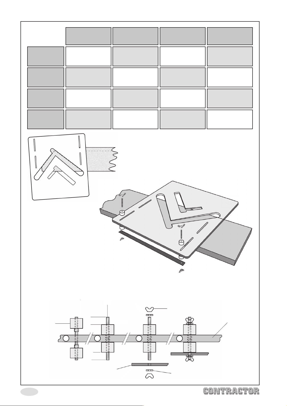
12. Attach the aluminium
spacers, (steps 1 to 4
below) to the relevant
slots in the jig, push
spacers firmly against the
edge of the string. Ensure an
equal amout of the stud is
visible on both sides when the
spacers are tightened (‘A’ = ‘B’).
Tighten the spacers by turning them in
opposing directions until tight (hand tight only).
Fit washer and wingnut on the top two studs and
gently tighten.
Attach the sliding bar to the bottom studs and secure with washers and wingnuts.
The jig is now fully assembled, and does not require dissasembling for storage etc.
To use agin, simply loosen wingnuts and spacers, adjust the jig accordingly.
Ø22mm Cutter
7mm Offset
Bush 2
Ø16mm Cutter
8mm Offset
Bush 3
Ø22mm Cutter
7mm Offset
Bush 1
Ø22mm Cutter
5mm Offset
Bush 3
11. Line up The jig perfectly with the two offset lines,
as per diagram Clamp the jig firmly to the string
in this position.
Ø16mm Cutter
8mm Offset
Bush 4
Ø22mm Cutter
5mm Offset
Bush 4
Aluminium
Spacer X 4
-7-
Threaded Stud X 2
‘A’
1 2
‘B’
Sliding Bar
Wing Nut X 4
Jig
3 4
Washer X 4

13. Attach the correct nosing bush and cutter size to the router, set the plunge depth
to 12mm (refer to tabIe on page 7 for correct guide bush and Cutter).
The edge of bush has to be flat with inside edge of jig
to ensure correct nosing and gap thickness for tread.
Ensure the long side of the guide
bush is flat against the side of the aperture to ensure a
correct size nose and width of cut for the tread to fit
comfortably.
14. Proceed to cut out the tread and riser
housing using the sequence shown in
diagram (right). Always refer to router
manufacturers instructions before
commencing.
Pitch Angle Line
Next jig position
15. You should now have completed the
first going and riser recess on the first
string. To complete the succession of
goings and risers along this string, the jig
must be moved sequentially along the
string. The distance between each movement of the Jig is equal to the length of the
pitch angle line (See diagram above), refer back to page 6 when steps were followed
to calculate the pitch angle line and the length measured. The angle of the pitch is
maintained by the sliding bar mechanism.
The procedure to follow is to mark a line along the margin where the right hand side of
the stair jig crosses. From this point, measure the length of the pitch angle line along the
margin and mark this point. This is the place at which to position the right hand side of the
stair jig for the next succession. Please ensure before re-clamping the jig, the sliding bar is
pushed firmly against the top edge of the string.
Repeat this procedure until the required number of rise and going recesses have been
cut.
IMPORTANT: whenever repositioning the jig, always ensure the spacers are pushed up
firmly against the edge of the string before clamping in position.
-8-
NOTE:
Enough room has to be left on the string before the first
riser is cut to ensure there is no break-out. It is better to
have more material, than not enough as the strings can
be cut to size afterwards.
16. All you need to do now is complete your “mirror image” string. The jig makes this very
simple. Remove the sliding bar from the spacers taking care not to move or loosen
them whilst doing so. Refit sliding bar on opposite side of the jig and secure in position
with the wingnuts, again taking care not to loosen or allow the spacers to move. The
jig is now prepared for the opposing string.
17. Draw the margin along the second string to the same distance as on the first. Next,
position the jig on the string, utilising the sliding bar to achieve the pitch angle and
ensuring that the first riser will not break out through the end of the string. See
diagram above. No measuring or calculating is required as the jig transfers all the
required datum information to the second string.
18. Repeat the succession of risers and treads along the second string in the same
).
way as the first string, (see point 15
Please note, you must, of course, use the same
pitch angle line distance as on the first string.
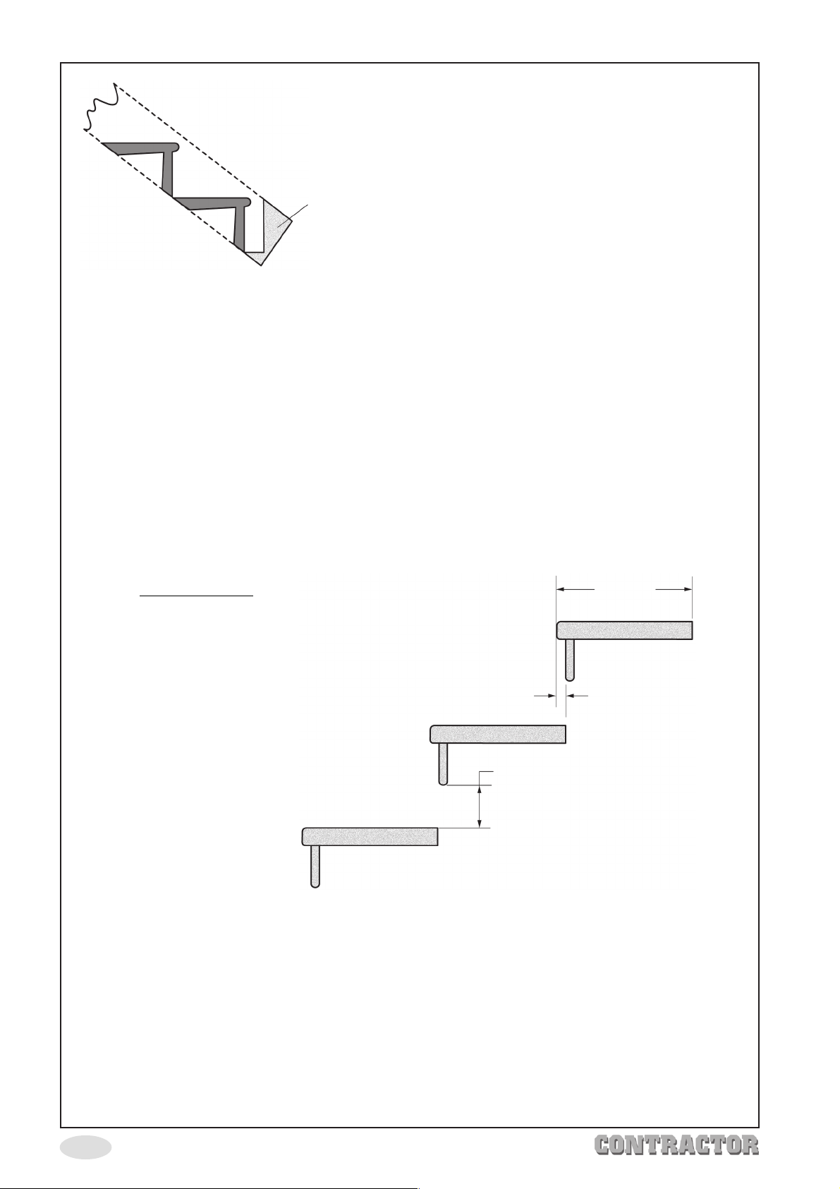
Open Stair Jig
260mm
The open stair jig works very much
in the same way as the closed
staircase, but the risers are left open.
Setting up follows the same
procedure as the closed staircase,
15mm Overlap
but there are a number of factors,
which the user will have to follow,
to ensure right construction, and to
comply with approved document K
Building Regulations 1985.
♦ A 30mm guide bush is used with a 16mm straight cutter, producing the correct gap
Gap MUST NOT Exceed 100mm
for the riser and tread.
♦ The tread has a fixed length of 260mm, with a thickness of 33mm.
♦ The radius of the base of the riser and the nosing of the tread is set at 8mm.
♦ The nosing on the tread has a fixed projection of 17mm.
♦ The tread should overlap each other by 15mm (see diagram above).
♦ The gap between the base of the riser and the upper face of the tread below should
not exceed 100mm. This is to ensure that a 100mm diameter sphere, the equivalent
of a child’s head, will not pass through the riser (see diagram above).
-9-

1. Follow the same procedure as in points 1 — 3 on page 5, making sure that the margin
is set at 44mm.
2. Calculate the rise with the going to make sure it complies with approved
document K. As there is an overlap of 15mm on the tread, the going is set at 245mm
as opposed to 260mm. Use this figure to calculate the relationship between the rise
and going making sure the final figure using the formula 2R + 6 falls between 550mm
and 700m.
3. Mark out your going and rise as in point 4, page 6, to calculate the pitch angle line,
and continue to follow steps 5 to 6 on page 6.
4. Follow point 10, marking an offset value of 7mm (page 6).
5. Follow procedure as for the closed stair jig, but remembering that the gap
between base of riser and upper face of lower tread does not exceed 100mm (see
diagram above). A block spacer can be put in the base of riser aperture on the jig
to decrease the length of the riser altering the gap accordingly.
6. Continue to slide the jig up the string sequentially following the procedure on
page 8 remembering to cut in the direction shown in the diagram.
7. The stair jig is flipped to opposite face on the opposing string in the same manner
as the construction of the closed staircase.
-10-

 Loading...