


BELT & DISC SANDER
MODEL NO: CS69D
PART NO: 6500421
OPERATION & MAINTENANCE
INSTRUCTIONS
ORIGINAL INSTRUCTIONS GC 0420 - ISS 1

INTRODUCTION
Thank you for purchasing this CLARKE Belt and Disc Sander. The CS69D is
designed for workshop use and comprises a 9” diameter sanding disc and a
6” wide sanding belt.
This machine is designed for sanding WOOD ONLY. DO NOT USE for sanding
asbestos or materials containing asbestos, painted surfaces, or materials
which produce toxic dust. Do not use for sanding magnesium as this produces
a highly flammable dust.
Before attempting to use this product, please read this manual thoroughly and
follow the instructions carefully. In doing so you will ensure the safety of yourself
and that of others around you and you can look forward to your purchase
giving you long and satisfactory service.
GUARANTEE
This product is guaranteed against faulty manufacture for a period of 12
months from the date of purchase. Please keep your receipt which will be
required as proof of purchase.
This guarantee is invalid if the product is found to have been abused or
tampered with in any way, or not used for the purpose for which it was
intended.
Faulty goods should be returned to their place of purchase, no product can
be returned to us without prior permission.
This guarantee does not effect your statutory rights.
ENVIRONMENTAL RECYCLING POLICY
By purchasing this product, the customer is taking on the obligation
to deal with its safe disposal in accordance with the Waste Electrical
and Electronic Equipment (WEEE).
In effect, this means that this product must not be disposed of with general
household waste. It must be disposed of according to the laws governing
Waste Electrical and Electronic Equipment (WEEE) at a recognised disposal
facility.
If disposing of this product or any damaged components, do not dispose of
with general waste. This product contains valuable raw materials. Metal
products should be taken to your local civic amenity site for recycling of metal
products.
2
Parts & Service: 020 8988 7400 / E-mail: Parts@clarkeinternational.com or Service@clarkeinternational.com

SPECIFICATIONS
Model no CS69D
Part no 6500421
Rated Voltage 230V ~ 50Hz
Power output 1.5 HP/1.1kW
Rated input wattage 1100W
Rated input ampere 4.8 A
Duty cycle S1 (continuous)
IP rating IPX0
Electrical insulation class Class 1
Fuse rating 13A
Disc Speed 1500 rpm
Sanding belt speed 5.8 m/s
Sound Pressure Level LpA 78.4 dB(A), Uncertainty Factor (K) 3 dB(A)
Sound Power Level LWA 91.4 dB(A), Uncertainty Factor (K) 3 dB(A)
Vibration
Less than 2.5 m/s
1.5m/s2
Dimensions (L x W x H) Sander - 720 mm x 520 mm x 980 mm
2
Uncertainty Factor (K)
Dimensions (L x W x H) Stand - 425 mm x 385 mm x 575 mm
Weight 40 kg
Dust extract port size 50.8 mm (2”)
Sanding belt size 152 mm x 1219 mm
Sanding disc size 228 mm dia (9”)
Sanding table size 300 x 150 mm
Tilt angle
Mitre gauge adjustment
0-45
-60
o
o
- +60
o
3
Parts & Service: 020 8988 7400 / E-mail: Parts@clarkeinternational.com or Service@clarkeinternational.com

POWER TOOL SAFETY WARNINGS
WORK AREA
1. Keep the work area clean and well lit. Cluttered and dark areas invite
accidents.
2. Do not operate power tools in explosive atmospheres, such as in the
presence of flammable liquids or gases. Power tools create sparks which
may ignite the dust or fumes.
3. Keep children and bystanders away while operating a power tool.
Distractions can cause you to lose control.
ELECTRICAL SAFETY
1. Power tool plugs must match the outlet. Never modify the plug in any way.
Do not use adaptor plugs with earthed (grounded) power tools. Unmodified
plugs and matching outlets will reduce the risk of electric shock.
2. Do not expose power tools to rain or wet conditions. Water entering a
power tool will increase the risk of electric shock.
3. Do not abuse the cable. Never use it for carrying, pulling or unplugging the
power tool. Keep the cable away from heat, oil, sharp edges or moving
parts. Damaged or entangled cables increase the risk of electric shock.
4. When operating a power tool outdoors, use an extension cable suitable for
outdoor use. Use of a cable suitable for outdoor use reduces the risk of
electric shock.
5. If operating the power tool in a damp location is unavoidable, use a
residual current device (RCD) protected supply.
PERSONAL SAFETY
1. Stay alert, watch what you are doing and use common sense when
operating a power tool. Do not use a power tool while you are tired or
under the influence of drugs, alcohol or medication. A moment of
inattention while operating power tools may result in personal injury.
2. Use safety equipment. Always wear eye protection. Safety equipment such
as dust mask, non-skid safety shoes, hard hat, or hearing protection used
for appropriate conditions will reduce personal injuries.
3. Avoid accidental starting. Ensure the switch is in the off position before
plugging in. Carrying power tools with your finger on the switch or plugging
in power tools that have the switch on invites accidents.
4. Do not overreach. Keep proper footing and balance at all times. This
enables better control of the power tool in unexpected situations.
4
Parts & Service: 020 8988 7400 / E-mail: Parts@clarkeinternational.com or Service@clarkeinternational.com

5. Dress properly. Do not wear loose clothing or jewellery. Keep your hair,
clothing and gloves away from moving parts. Loose clothes, jewellery or
long hair can be caught in moving parts.
POWER TOOL USE AND CARE
1. Do not force the power tool. Use the correct accessories for your
application. The correct power tool will do the job better and safer at the
rate which it was designed for.
2. Do not use the power tool if the switch does not turn it on and off. Any
power tool that cannot be controlled with the switch is dangerous and
must be repaired.
3. Disconnect the plug from the power source before changing accessories,
or storing power tools. Such preventive safety measures reduce the risk of
starting the power tool accidentally.
4. Store idle tools out of the reach of children and do not allow persons
unfamiliar with the power tool or these instructions to operate it. Power tools
are dangerous in the hands of untrained users.
5. Maintain power tools. Check for misalignment or binding of moving parts,
breakage of parts and any other condition that may affect the power
tool’s operation. If damaged, have the power tool repaired before use.
Many accidents are caused by poorly maintained power tools.
6. Use the power tool and accessories in accordance with these instructions
and in the manner intended, taking into account the working conditions
and the work to be performed. Use of the power tool for operations
different from intended could result in a hazardous situation.
7. The performance of this tool may vary, depending upon variations in line
voltage. Extension cable usage may also affect performance.
SERVICING
1. Have your power tool serviced by qualified service personnel using only
identical replacement parts. This will ensure that the safety of the power
tool is maintained.
ADDITIONAL SAFETY WARNINGS FOR SANDERS
1. Dust arising from sanding may endanger the health of the operator and
possible bystanders. Wear a dust mask and ensure that persons entering
the work area are also protected.
2. Remove all dust after sanding.
3. Avoid sanding lead based paint, wood or metal which may produce toxic
dust, - do not let children or pregnant women enter the work area.
5
Parts & Service: 020 8988 7400 / E-mail: Parts@clarkeinternational.com or Service@clarkeinternational.com
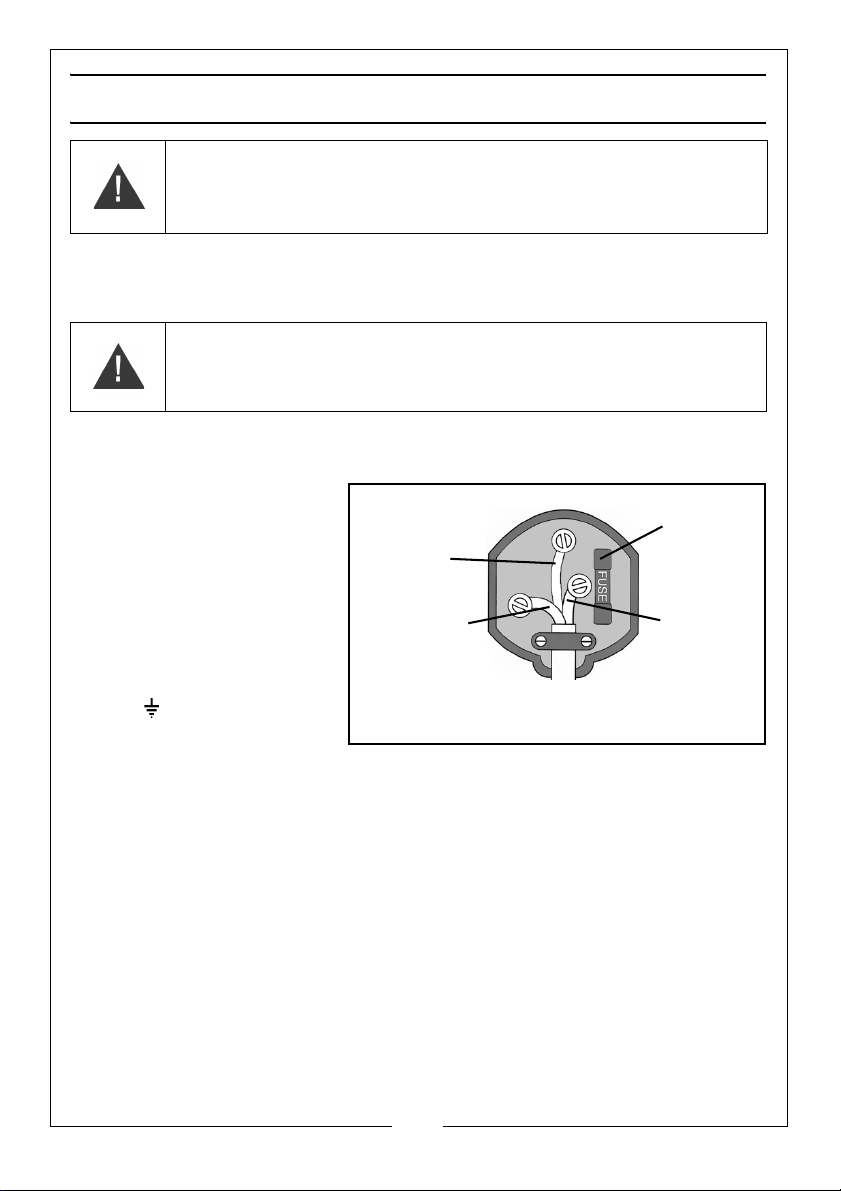
ELECTRICAL CONNECTIONS
Plug must be BS1363/A approved.
Always fit
Ensure that the outer sheath of
Neutral
(Blue)
Live
(Brown)
Earth
(Green and
a 13 Amp
the cable is firmly held by the clamp
fuse.
Yel low)
WARNING: READ THESE ELECTRICAL SAFETY INSTRUCTIONS FULLY
BEFORE CONNECTING THE PRODUCT TO THE MAINS SUPPLY.
This product is provided with a standard, 230 volt (50Hz), BS 1363 plug, for
connection to a standard, domestic electrical supply. Should the plug need
changing, make sure that a plug of identical specification is used.
WARNING: THE WIRES IN THE CABLE ARE COLOURED AS FOLLOWS:
BLUE = NEUTRAL BROWN = LIVE YELLOW AND GREEN = EARTH
If the colours of the wires in the power cable do not correspond with the
markings on the terminals of your plug, proceed as follows.
• Connect the blue wire
to the terminal
marked N.
• Connect the brown
wire to the terminal
marked L.
• Connect the yellow
and green wire to the
terminal marked E or
.
AN APPROVED RESIDUAL CURRENT DEVICE (RCD) WHICH HAS A TRIPPING
CURRENT OF LESS THAN 30MA MUST BE USED.
If you are not sure, consult a qualified electrician. DO NOT try to do any
repairs.
Parts & Service: 020 8988 7400 / E-mail: Parts@clarkeinternational.com or Service@clarkeinternational.com
6

EXPLANATION OF SYMBOLS & PICTOGRAMS
Read instruction manual before use.
Wear safety glasses or goggles when using the tool.
Wear ear protection when using this tool.
Wear a dust mask.
Wear protective gloves.
For indoor use only
7
Parts & Service: 020 8988 7400 / E-mail: Parts@clarkeinternational.com or Service@clarkeinternational.com

INVENTORY
The CS69D sander is supplied with the following items which will require
assembly.
• Stand assembly kit, comprising: - 2 x side panels, 2 x short cross members,
2 x long cross members, 4 x rubber feet with flat washers & nuts, 12 x M8
coach bolts /12 x M8 plain washers/12 x M8 nuts.
• 1 x Hex wrench (long)
• 1 x Spanner (10-13mm)
•1 x Workstop
• 1 x Drive housing
• 1 x Sanding face plate
• 1 x Drive cover c/w fixing screws
• 1 x Small (motor) pulley
• 1 x Large (driven) pulley
• 1 x Drive belt
• 1 x Work table assembly
• 1 x Table support rod
• 1 x Mitre fence assembly
• 1 Fixing kit containing, grubscrews, parallel keys, 4 x bolts,4 x spring
washers, 4 x large washers (sander to stand fixings), workstop retaining
bolt/washer.
• 1 x Abrasive disc
• 1 x Abrasive belt
8
Parts & Service: 020 8988 7400 / E-mail: Parts@clarkeinternational.com or Service@clarkeinternational.com

BEFORE USE
ASSEMBLING THE STAND
Assemble the stand as shown. The upper and lower beams are secured with
the 12 x M8 coachbolts with flat washers & nuts. Add the rubber feet securing
them with flat washers & nuts.
Do not tighten the nuts until all bolts are in place and the stand is rocked to
ensure it is stable and evenly assembled. When satisfied, tighten securely.
WITH ASSISTANCE, considering its weight, place the sander on top of the stand.
Position it so that the bolt holes, viewed from below, line up. Enter the 13mm
bolts fitted with flat and lock washers and tighten securely from below.
FITTING THE DRIVE COMPONENTS
1. Fit the drive housing to the frame
using 4 x M8 x12 retaining bolts
and flat washers.
9
Parts & Service: 020 8988 7400 / E-mail: Parts@clarkeinternational.com or Service@clarkeinternational.com
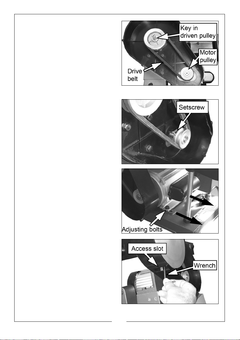
2. Slide the 5 x 55 mm parallel key
into the groove in the shaft and
slide driven pulley onto the end of
the driven shaft, engaging with
the key.
3. Pass the drive belt over both
pulleys and slide the motor pulley
onto the motor shaft complete
with the 5 x 25 mm parallel key.
4. Press both pulleys onto the shafts
as far as they will go. This will ensure that they are correctly aligned.
5. Using the hex wrench supplied,
tighten the M8 x 10 setscrews to
secure the both pulleys.
6. Tension the drive belt as necessary
by adjusting the position of the
motor on the bedplate using the 4
adjusting bolts.
• As a rough guide, aim for
approx 12mm deflection at the
mid-point of the drive belt and
confirm there is no slippage of
the belt on the pulleys.
7. Slide the face plate onto the
driven shaft, engaging with the
parallel key already in postion.
8. Use the hex wrench supplied to
tighten the setscrew and secure
the face plate to the driven shaft,
inserting the wrench through the
access slot in the drive cover.
10
Parts & Service: 020 8988 7400 / E-mail: Parts@clarkeinternational.com or Service@clarkeinternational.com

9. Check that the surface of the
face plate is clean and attach
the abrasive disc after peeling off
the backing material. Take great
care to position it centrally.
10. Fit the drive cover using the selftapping screws.
Fit the work stop to the frame using
the M8 x 20 bolt and flat washer.
CHECKS BEFORE USE
As with all machinery, it is important to ensure that the various components are
properly secure and in good order before use.
The sander is designed so that when switched ON, both the belt AND the disc
will rotate. It is also important therefore, to ensure that the belt runs true on the
rollers, referred to as ‘Tracking’. Although the necessary adjustments have
been carried out at the factory, it is nevertheless prudent to perform this
check when first setting up your machine in the event it has been disturbed
during transit.
11
Parts & Service: 020 8988 7400 / E-mail: Parts@clarkeinternational.com or Service@clarkeinternational.com

CHECKING THE BELT TRACKING
The rollers must run parallel, otherwise
the belt will be driven off to one side.
1. Plug in to the mains supply and
press the GREEN ON button,
marked ‘I’ to start the machine.
keeping well away from the belt.
2. Observe the belt for a short period
as it passes over the front
roller....there should be no creep
to one side. If it does creep, switch
OFF by pressing the RED OFF button, marked ‘O’.
To perform the adjustment, release the locking knob on each side of the
machine and turn the adjusting wheel to either slacken or tension one side of
the abrasive belt. Note that only small adjustments should be required.
3. Restart the machine and screw the adjusting wheels very gently in or out to
compensate for the creep. When the belt is running true, switch off and
tighten the locking knobs. When satisfied, restart and check the tracking is
now correct. If necessary, repeat until the belt runs true.
FITTING THE WORK TABLE FOR USE WITH THE DISC
The mounting of the work table will depend upon the job in hand, i.e. either
adjacent to the disc or to the belt.
The table is mounted on a support bar which is inserted into the housing on the
machine base and secured with 2 x M8x20 setscrews.
1. Tighten the securing setscrews to secure the support bar in the base.
2. Slide the table assembly on to the
support bar and bring the table to
within 2mm of the sanding disc.
Tighten the securing setscrew in
the table frame to secure it to the
support rod.
12
Parts & Service: 020 8988 7400 / E-mail: Parts@clarkeinternational.com or Service@clarkeinternational.com

3. To ensure the table is at exactly
o
to the sanding disc, position a
90
small engineers set square on the
table so that it touches the disc.
Slacken off the table angle
adjustment knob, shown and
adjust accordingly so that the
table sits level.
4. Tighten the adjustment knob and
if necessary, zero the pointer
adjacent to the scale by
slackening the securing screw and repositioning.
FITTING THE WORK TABLE FOR USE WITH THE BELT
1. When using the work table with
the sanding belt in the upright
position, remove the work stop
from the belt frame by removing
the workstop securing bolt.
2. Before attaching the table to the
mounting, raise the sanding belt
arm and secure in position using
the locking bolt shown. An open
spanner is provided for this.
3. Slide the table support rod into
the mounting as shown and
tighten the two securing
setscrews.
4. Mount the table on the support
bar, bring to within 2 mm of the
belt and tighten the securing
setscrew. Ensure the table is level.
5. To ensure the belt is perpendicular
to the table, use an engineers
square as described above, adjusting the angle of the sanding belt arm
using the arm locking bolt shown.
6. Ensure the work stop is replaced correctly when returning the belt to the
horizontal position.
13
Parts & Service: 020 8988 7400 / E-mail: Parts@clarkeinternational.com or Service@clarkeinternational.com
METHOD OF USE
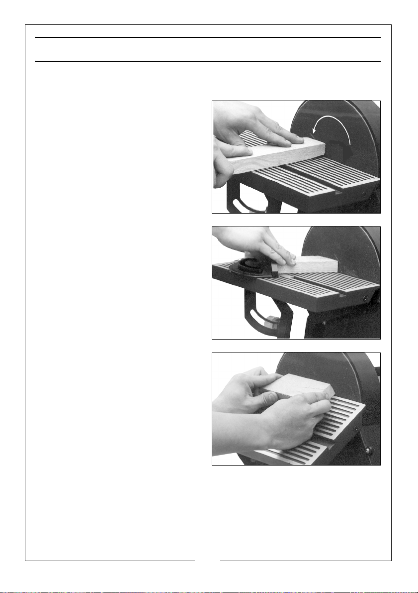
USING THE DISC
1. Check that the table is
approximately 2mm from the
sanding disc before switching on.
2. Hold the work firmly as shown and
ALWAYS hold the workpiece
against the left half of the disc. i.e.
that half moving downwards
towards the sanding table.
3. DO NOT exert too much pressure.
A light touch is all that is required.
• The photo shows the table
being used in conjunction with
the mitre gauge.
4. Set the gauge to the angle you
require and hold the workpiece
firmly against the gauge, feeding
it gently against the sanding disc.
5. Keep the workpiece in contact
with the left side of the disc as far
as possible.
• The illustration shows the
sanding table set to an angle.
The mitre gauge may also be
used with this setup.
• Angles up to 45o may be set.
6. If accuracy is required, check the
angle using a suitable square or
template.
14
Parts & Service: 020 8988 7400 / E-mail: Parts@clarkeinternational.com or Service@clarkeinternational.com

USING THE BELT
The work stop must be in place when
using the belt horizontally.
1. Secure using the bolt and flat
washer as shown.
2. Ensure a gap of no more than
2mm exists between the belt and
the work stop.
3. The belt can be used in the
vertical position as shown. In this
case, the work stop should be
removed. Lock the belt frame in
the upright position using the arm
locking bolt shown on page 13.
The belt is used for long workpieces,
as shown. The workpiece is driven
against the work stop by the action
of the belt.
• DO NOT exert too much
pressure - a light touch is all that
is required.
• Curves may be sanded as
shown.
4. Let the sander do the work and
ensure the workpiece is flat on the
table surface. Never apply heavy
pressure as this will not only
produce an uneven finish but will
overload the motor causing it to
burn out.
5. On very uneven surfaces or when removing layers of paint, start with a
coarse grit. On other surfaces, start with a medium grit. In both cases,
gradually change to a fine grit for a smooth finish. Regularly check the
condition of the sanding belt or disc and replace it when necessary.
15
Parts & Service: 020 8988 7400 / E-mail: Parts@clarkeinternational.com or Service@clarkeinternational.com

DUST EXTRACTION
WARNING: HARMFUL OR TOXIC DUST MAY BE PRODUCED WHEN
SANDING LEAD PAINTED SURFACES, WOODS OR METAL. CONTACT WITH,
OR INHALATION OF THESE DUSTS CAN ENDANGER THE HEALTH OF THE
OPERATOR OR BYSTANDERS. CERTAIN DUSTS LIKE OAK AND BEECH ARE
CONSIDERED TO BE CANCEROUS IN CONJUNCTION WITH ADDITIVES IN
WOOD TREATMENTS (CHROMATE, WOOD PRESERVATIVES). ASBESTOSCONTAINING MATERIALS MAY ONLY BE HANDLED BY EXPERTS.
WARNING: - USE A DUST EXTRACTION DEVICE OR A VACUUM CLEANER.
WARNING: - WORK IN A WELL VENTILATED ROOM.
WARNING: -THE USE OF A DUST MASK FILTER CLASS P2 IS RECOMMENDED.
- OBSERVE LOCAL REGULATIONS REGARDING THE HANDLING OF
CERTAIN MATERIALS.
Provision is made for dust extraction
from both the disc and belt.
The dust extraction outlets are shown
and have a diameter of 51mm (2”).
Connect a suitable hose to a
vacuum cleaner via a reducer if
required, or dust extraction device
(see your CLARKE dealer).
NOTE: The user should still wear a
face mask to prevent the
inhalation of dust particles.
Due to the nature of the sander some of the dust produced will be forced into
the surrounding atmosphere and will not be collected.
16
Parts & Service: 020 8988 7400 / E-mail: Parts@clarkeinternational.com or Service@clarkeinternational.com

MAINTENANCE
WARNING: BEFORE PERFORMING ANY MAINTENANCE, SWITCH OFF AND
UNPLUG THE SANDER.
Your sander will operate over a long period of time with a minimum of
maintenance. Continuous satisfactory operation depends upon proper care.
Regularly clean the motor ventilation slots using a soft dry brush, cloth or
vacuum cleaner and remove undue buildup of dust from the sander. Do not
use any abrasive or solvent-based cleaner.
A damaged power cable should be replaced by your CLARKE dealer or
qualified electrician.
The bearings in this sander are sealed for life and require no maintenance.
CHANGING THE BELT
1. Disconnect any dust extract hoses
connected to the machine.
2. Remove the lower belt cover by
slackening the six securing screws
sufficiently for the cover to be
slipped off the frame.
3. Tilt the frame assembly up in order
that the belt cover remains away
from the belt.
4. Lock the bed in the upright
position using the locking nut.
5. Release the belt tension locking
knobs and unscrew the belt
adjusting wheels until the belt
goes slack.
The belt may now be slipped off and
replaced by a new one. Drop the
frame back to the horizontal position
and refit the belt guard/cover.
6. Tension the belt by the belt
tension adjusting wheels.
7. Check the belt tracking as previously described on page 12.
17
Parts & Service: 020 8988 7400 / E-mail: Parts@clarkeinternational.com or Service@clarkeinternational.com
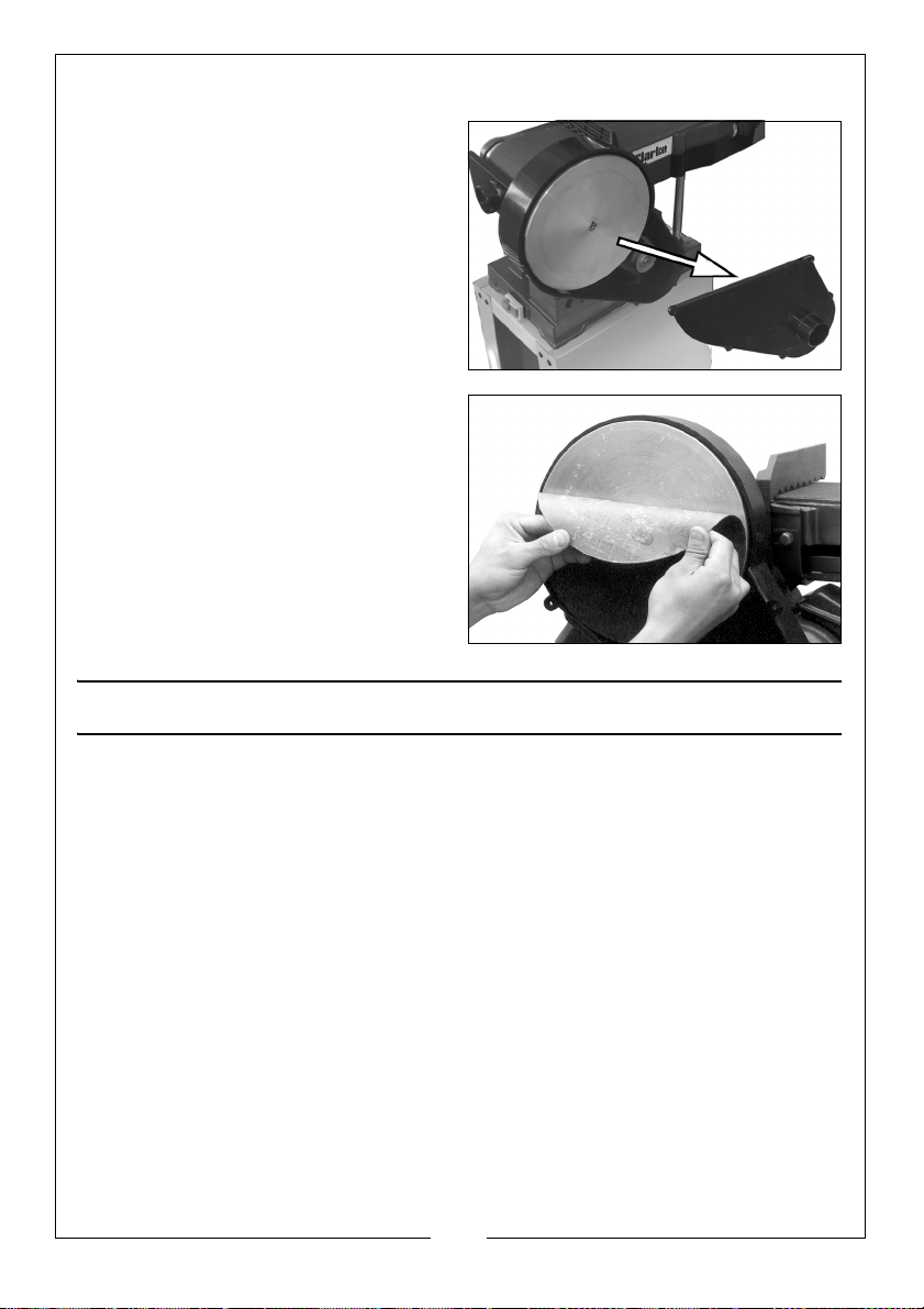
CHANGING THE DISC
1. Remove the screws and lift away
the drive cover as shown then
peel the abrasive disc from the
faceplate.
2. Clean any residual adhesive from
the faceplate and refit a new
abrasive disc, taking great care
that it is central. Ensure it is evenly
attached across its surface.
3. When satisfied, replace the drive
cover.
FAULTFINDING
SANDER IS OVERHEATING
Overloading the machine will cause overheating. do not apply excessive
pressure when working. The motor may over heat if covered in dust which can
be blown out with compressed air. Always wear eye protection and a dust
mask when using compressed air.
EXCESSIVE MOTOR SPARKING OCCURS
This indicates worn brushes. This problem is quickly remedied but you should
consult your CLARKE dealer for parts and advice.
SANDER DOES NOT OPERATE WHEN SWITCHED ON
Check to ensure the fuse is sound and replace if necessary. If the fuse is sound
or blows repeatedly, consult your CLARKE dealer.
POOR ABRASION
If the sander is not removing material efficiently, check the sanding sheet. If
the abrasive is worn down replace the sheet. The sanding sheet must always
18
Parts & Service: 020 8988 7400 / E-mail: Parts@clarkeinternational.com or Service@clarkeinternational.com

be stored in a dry place as if it allowed to become damp, the abrasive
particles will detach from the sheet and will not abrade.
POOR DRIVE
If the sander does not reach full speed or slows down during hard sanding, the
main drive belt may be slipping. Tension the belt by means of the adjsuting
bolts shown on page 10.
ACCESSORIES
Replacement discs and belts are available in packs of 5 from your CLARKE
dealer.
Please quote the part numbers below.
6” Replacement belts (150 x 1219mm) Part Number
Fine 6502098
Medium 6501164
Coarse 6502103
Replacement 9”discs Part Number
Fine 6502099
Medium 6501076
Coarse 6502100
19
Parts & Service: 020 8988 7400 / E-mail: Parts@clarkeinternational.com or Service@clarkeinternational.com

PAR T S DI AGR AM
20
Parts & Service: 020 8988 7400 / E-mail: Parts@clarkeinternational.com or Service@clarkeinternational.com

PAR TS L IST
No Description No Description
1 Abrasive belt 31 M8 x 10 set screw
2 Bearing cover 32 Abrasive disc
3 Circlip 33 Disc cover
4 Bearing 34 Pointer
5 M8 nut 35 4mm flat washer
6 Lock washer 36 4mm lock washer
7 Drum cover 37 M4 x 5 pan head screw
8 M8x10 set screw 38 Lock knob
9 Connecting rod 39 Mitre gauge
10 Abrasive belt guard 40 Guide bar
11 Drive drum 41 Table
12 5 x 55 mm key 42 Angle plate
13 Drive shaft 43 8mm washer
14 Bearing 44 M8 x 12 bolt
15 Washer 45 Locking knob
16 Circlip 46 8mm flat washer
17 M8 x bolt 47 M5 x 40 flat head bolt
18 8mm flat washer 48 M5 hex nut
19 Bracket 49 Pointer
20 Spacer plate 50 M8 x 10 set screw
21 M8 x 40 carriage bolt 51 Table support
22 Belt housing 52 Nut
23 M8 x 10 set screw 53 M5 x 40 flat head bolt
24 Driven pulley 54 M5 hex nut
25 M8 x 10 set screw 55 Self tapping screw
26 Motor pulley 56 Support bar
27 8mm washer 57 M5 x 16 pan head screw
28 M8 x 12 bolt 58 Washer
29 V-belt 59 Power cable
30 Aluminium disc 60 Terminal
21
Parts & Service: 020 8988 7400 / E-mail: Parts@clarkeinternational.com or Service@clarkeinternational.com

61 5mm flat washer 90 M6 nut
62 5mm lock washer 91 M8 nut
63 M5 hex nut 92 8mm lock washer
64 Switch 93 8mm flat washer
65 Self tapping screw 94 Strain relief 1
66 Switch plate 95 Strain relief 2
67 M8 x 20 set screw 96 M8 x 20 bolt
68 Base 97 M8 x 10 setscrew
69 Cable clamp plate 98 5mm flat washer
70 5mm flat washer 99 M5 x 20 pan head screw
71 M5 hex nut 100 5 x 25 key
72 5mm lock washer 101 Motor
73 Switch box 102 Support rod
74 Top frame 103 M8x20 bolt
75 M6 x 12 carriage bolt 104 8mm flat washer
76 Brace 105 Work stop
77 M6 x 12 carriage bolt 106 Belt frame
78 Rubber foot 107 Lock knob
79 M8 x 25 socket head bolt 108 Tracking nut
80 8mm flat washer 109 Drum cover
81 8mm flat washer 110 Circlip
82 M8 nut 111 Bearing
83 6mm flat washer 112 Shaft
84 M6 nut 113 M5 x 6 setscrew
85 Leg 114 Adjusting nut
86 M8 x 16 bolt 115 Idler drum
87 8mm lock washer 116 6mm flat washer
88 8mm flat washer 117 M6 x 10 pan head screw
89 6mm flat washer
22
Parts & Service: 020 8988 7400 / E-mail: Parts@clarkeinternational.com or Service@clarkeinternational.com

DECLARATION OF CONFORMITY
23
Parts & Service: 020 8988 7400 / E-mail: Parts@clarkeinternational.com or Service@clarkeinternational.com

 Loading...