

Page 1
BELT & DISC SANDER
BELT & DISC SANDER
MODEL No. CS6-9C
Part No. 6500420
OPERATING & MAINTENANCE
INSTRUCTIONS
0614
Page 2

INTERNATIONAL
DECLARATION OF CONFORMITY
We declare that this product complies to the following
standards/directives:
73/23/EEC
EN 60 995
09/336 EEC
Product Description: BELT & DISC SANDER
Model Number: CS6-9C
Serial (Batch) No: See Product Data Plate
Signed....................................................................
Hemnall Street,Epping, Essex CM16 4LG
DOC No.Z001/10 Clarke International is a trading style of Clarke International Limited
Page 3

Thank you for purchasing this CLARKE Belt and Disc Sander, which is designed for workshop
use and comprises a 9” dia. sanding disc and a 6” wide sanding belt.
This machine is designed for sanding WOOD ONLY. DO NOT USE for sanding asbestos, or
materials containing asbestos, painted surfaces, or materials which produce toxic dust. Do
not use for sanding magnesium as this produces a highly flammable dust.
Before attempting to operate this machine, please read this instruction manual thoroughly
and follow all directions carefully. By doing so you will ensure the safety of both yourself and
others around you, and at the same time, you should look forward to long and trouble free
service from your Sander.
GUARANTEE
This product is guaranteed against faults in manufacture for 12 months from purchase date.
Keep your receipt as proof of purchase.
This guarantee is invalid if the product has been found to have been abused in any way, or
not used for the purpose for which it was intended, or to have been tampered with in any
way. The reason for return must be clearly stated.
This guarantee does not affect your statutory rights.
CONTENTS PAGE
Guarantee ...................................................................................................... 3
Parts & Service Contacts ............................................................................... 3
General Safety Rules ...................................................................................... 4
Special Safety Rules for Belt Sanders ........................................................... 4
Electrical Connections, Fuse Rating ............................................................. 5
Pre-Assembly Check ..................................................................................... 6
Assembly ........................................................................................................ 7
Checks Before Use ......................................................................................... 7
Fitting the Table .............................................................................................. 8
Methods of Use ............................................................................................... 9
Dust Extraction ................................................................................................ 11
Maintenance .................................................................................................. 12
Accessories .................................................................................................... 13
Specifications ................................................................................................. 13
Parts List and Diagram ................................................................................... 14-15
Environmental Recycling Policy
Through purchase of this product, the customer is taking on the obligation to deal
with the WEEE in accordance with the WEEE regulations in relation to the
treatment, recycling & recovery and environmentally sound disposal of the WEEE.
In effect, this means that this product must not be disposed of with general
household waste. It must be disposed of according to the laws governing Waste
Electrical and Electronic Equipment (WEEE) at a recognised disposal facility.
- 3 -
Page 4

GENERAL SAFETY RULES
1.
ALWAYS
check they are not damaged.
2.
ALWAYS
WRENCHES. Make a habit of checking
to see that all adjusting keys and
wrenches are removed from machine
before turning it on.
3.
ALWAYS
Cluttered areas and work benches
invite accidents
4. ALWAYS KEEP CHILDREN AWAY. All
visitors, but in particular children, should
be kept at a safe distance away from
the work area.
5. ALWAYS MAKE YOUR WORKSHOP
CHILDPROOF with padlocks, master
switches, or by removing starter keys.
6. ALWAYS WEAR THE PROPER APPAREL.
No loose clothing, gloves, neckties, rings,
bracelets, or any other jewellery which
might get caught in moving parts.
Non-slip footwear is recommended.
Long hair should be contained.
7. ALWAYS USE SAFETY GLASSES. Everyday
glasses only have impact resistant
lenses, they are not safety glasses. Also
use a face mask if a lot of dust is
generated.
8. ALWAYS KEEP A FIRM FOOTING and
proper balance at all times.... do not
overreach.
KEEP GUARDS IN PLACE and
REMOVE ADJUSTING KEYS AND
KEEP WORK AREA CLEAN.
9. ALWAYS DISCONNECT FROM THE MAINS
before attempting any kind of service
work or adjustment or when changing
accessories such as grinding wheels.
10. ALWAYS MAINTAIN TOOLS WITH CARE.
Keep tools sharp and clean for best
and safest performance.
11. ALWAYS make sure switch is in the OFF
position before plugging in order to
reduce the risk of unintentional starting.
12. ALWAYS CHECK FOR DAMAGED PARTS.
Before using the machine, check parts
for signs of damage, and to ensure they are
secure. If a component suffers slight
damage, (eg. a distorted guard or
bracket), make sure it will perform its
intended function properly before switching
on. If in doubt, do not use the machine.
ALWAYS be prepared to SWITCH OFF
IMMEDIATELY, if you experience unusual
noises, or excessive vibration. Do not use the
machine until the fault is fully rectified.
13. NEVER FORCE YOUR Sander. It will do a
better and safer job if used at the rate for
which it was designed.
14. NEVER USE IN A DANGEROUS
ENVIRONMENT. Do not use any power
tools in damp or wet areas, or expose
them to rain. Keep work area well lit.
ADDITIONAL SAFETY RULES FOR SANDERS
4.
1.
ALWAYS
2.
ALWAYS
wear eye protection
use the work stop or table
to support the workpiece.
3.
ALWAYS
sanding belt arm and attachments are
secure before starting.
check to ensure the table and
ALWAYS
between table and sanding belt or disc.
5.
ALWAYS
that it cannot be ripped from your hands
6.
ALWAYS
direction of rotation of the disc or belt.
WARNING! Use ONLY for sanding WOOD. DO NOT DO NOT USE for sanding asbestos,
or materials containing asbestos, painted surfaces, or materials which produce toxic
dust. Do not use for sanding magnesium as this produces a highly flammable dust.
- 4 -
maintain a clearance of 2mm
hold the workpiece firmly so
feed the workpiece against the
Page 5

ELECTRICAL CONNECTIONS
Connect the mains lead to a standard, 230 volt (50Hz) electrical supply through a
fused good quality 13 amp BS 1363 plug, or a suitable fused isolator switch.
WARNING: THIS APPLIANCE MUST BE EARTHED
IMPORTANT: The wires in the mains lead are coloured in accordance with the
following code:
Green & Yellow - Earth
Blue - Neutral
Brown - Live
As the colours of the flexible cord of this appliance may not correspond with the
coloured markings identifying terminals in your plug, proceed as follows:
• Connect GREEN & YELLOW cord to terminal marked with a letter “E” or Earth
symbol “ ” or coloured GREEN or GREEN & YELLOW.
• Connect BROWN cord to terminal marked letter “L” or coloured RED.
• Connect BLUE cord to terminal marked letter “N” or coloured BLACK.
We strongly recommend that this unit is fitted with a Residual Current Device (RCD).
FUSE RATING
The fuse in the plug for this appliance must be rated at 13 amps and any
replacement must be ASTA approved to BS1362.
IMPORTANT NOTICE
If this appliance is fitted with a plug which is moulded on to the electric cable (i.e.
non rewireable) please note:
1. This plug must be thrown away if it is cut from the electric cable. There is a
danger of electric shock if it is subsequently inserted in a socket outlet.
2. Never use the plug without the fuse cover fitted.
3. Should you wish to replace a detachable fuse carrier, ensure that the correct
replacement is used (as indicated by marking or colour code).
4. Replacement fuse covers can be obtained from your local dealer, or an
electrical stockist.
5. The fuse in the plug must be 13Amps,
- 5 -
Page 6
PRE-ASSEMBLY CHECK
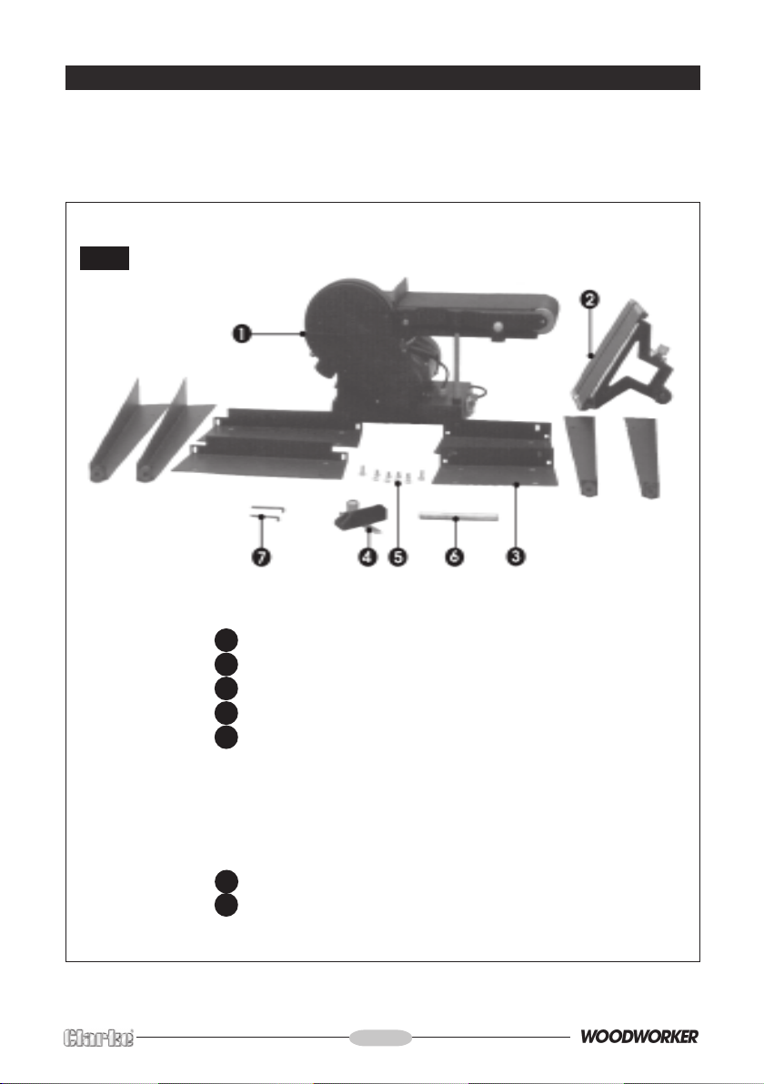
Unpack the carton and lay out the components and loose items. Check against the list
below to ensure that all parts are present. If any damage has occurred during transit, please
contact your Clarke dealer immediately.
Fig.1
1. Main Body complete
2 Table Assembly complete
3 Leg Assembly, comprising 8 parts
4 Mitre Gauge Assembly
5 Leg Assembly Fixing Screws, comprising
20 x M8 Coach Bolts
20 8Ø Plain Washers
4 x M6 Screws
4 X 6Ø Plain Washers
4 x 6Ø Spring Washers
6 Table Support Bar
7 2 x Hex Wrenches
- 6 -
Page 7
ASSEMBLY
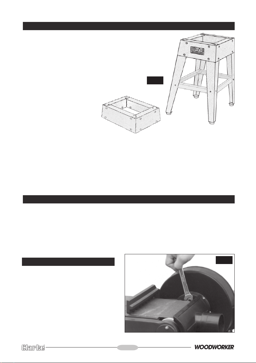
1. Assemble the stand in the manner shown in Fig.2.
The four top panels are secured with a single bolt,
with flat washer, in each corner, and the legs are
then bolted on, followed by the leg braces.
Do not tighten the nuts until all bolts are in place
and the stand is rocked vigorously to ensure it is
stable. When satisfied, tighten securely.
Fig.2
2. WITH ASSISTANCE, considering its
weight, raise the machine and
place it on top of the
stand.
Manoeuvre it so that the
bolt holes, viewed from
below, line up. Enter the
M6 screws fitted with flat and
lock washers and tighten securely.
3. Screw the Belt Tensioning Lever (see Fig.4) securely into its housing.
NOTE:
Except for the table, your Sander is now fully assembled. The location of the Table will depend
upon the job in hand, i.e. either adjacent to the disc or the belt. Table fitting and adjustments
are described on pages 8 and 9.
The machine is fitted with a Sanding Disc and Sanding Belt at the factory.
CHECKS BEFORE USE
As with all machinery, it is important to ensure that the various components are properly
secure and in good order before use.
The machine is designed so that when switched ON, both the belt AND the disc will rotate.
It is also important therefore, to ensure that the belt runs true on the rollers, referred to as
‘Tracking’. Although the necessary adjustments have been carried out at the factory, it is
nevertheless prudent to perform this check when first setting up your machine, in the event
it has been disturbed during transit.
Belt Tracking Check
The rollers must run parallel, otherwise the
belt will be driven off to one side. To
perform the check, ideally the belt
should be in the vertical position, as this
position provides greater safety for the
operator.
To raise the belt to its vertical position,
slacken off the two securing screws, one
of which is shown in Fig. 3, the other is
diametrically opposed. Then raise the
arm, and retighten the two screws.
- 7 -
Fig. 3
Page 8
With the belt raised, ensure that nothing can interfere
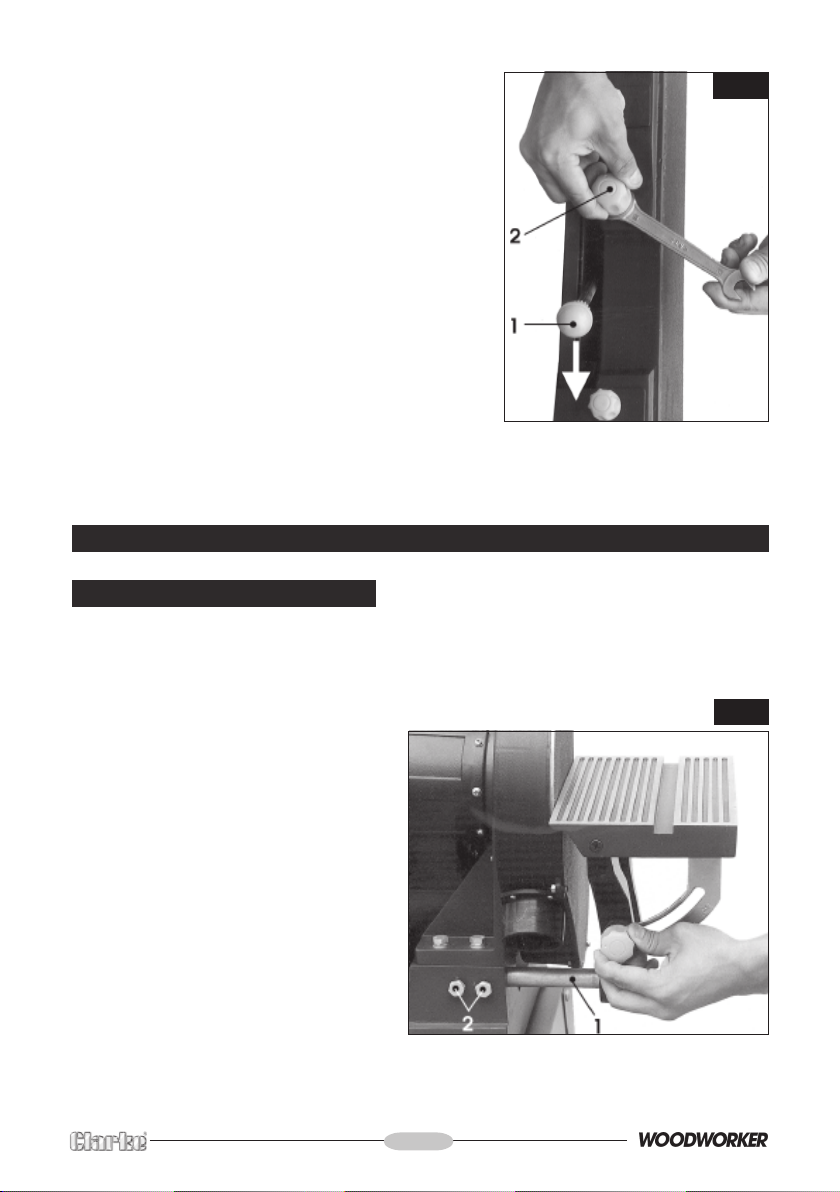
with the disc or belt, and that the Belt Tensioning Lever
(1, Fig.4), is pushed fully to the rear - in the direction
of the arrow.
Plug in to the mains supply and press the GREEN ON
button, marked ‘I’ to start the machine. keeping well
away from the belt.
Observe the belt as it passes over the front (top)
roller....there should be no creep to one side. If it does
creep, switch OFF by pressing the RED OFF button,
marked ‘O’.
Adjacent to the belt tensioning lever, is the Roller
Adjustment Knob (2, Fig.4). Slacken the locknut as
shown in fig. 4 and back the nut off a turn or two.
Restart the machine, and screw the Adjuster Knob
very gently in or out to compensate for the creep.
When the belt is running true, switch OFF and tighten
the locknut, ensuring you do not allow the adjuster knob to turn. When satisfied, restart and
check. If necessary, repeat until the belt runs true.
Fig. 4
FITTING THE TABLE
A ...to the Disc
The Table is mounted on a Support Bar (6, Fig.1 and 1, Fig.5). ‘Flats’ are milled at each end
of the bar. Insert the end with the shorter length flat into the housing on the machine.
NOTE: It may be necessary to unscrew the two securing screws (2,Fig.5) in order for the bar
to be inserted fully.
Tighten the securing screws.
Fig. 5
Slide the table assembly on to the
support bar, and bring the table to within
2mm of the disc, then tighten the two
securing screws (1, Fig.6).
To ensure the table is at exactly 90o to
the disc, place a small engineers square
on the table and bring up to the disc.
Slacken off the Table Angle Adjustment
Knob, shown in Fig.5, and adjust
accordingly so that the table is true.
Tighten the adjustment knob, and if
necessary, zero the pointer, adjacent to
the scale, by slackening the securing
screw and repositioning.
- 8 -
Page 9
B...to the Belt
Before attempting to attach the table to
the belt mounting, raise the belt arm and
secure with the two securing screws, as
explained under ‘Checks Before Use’, p7.
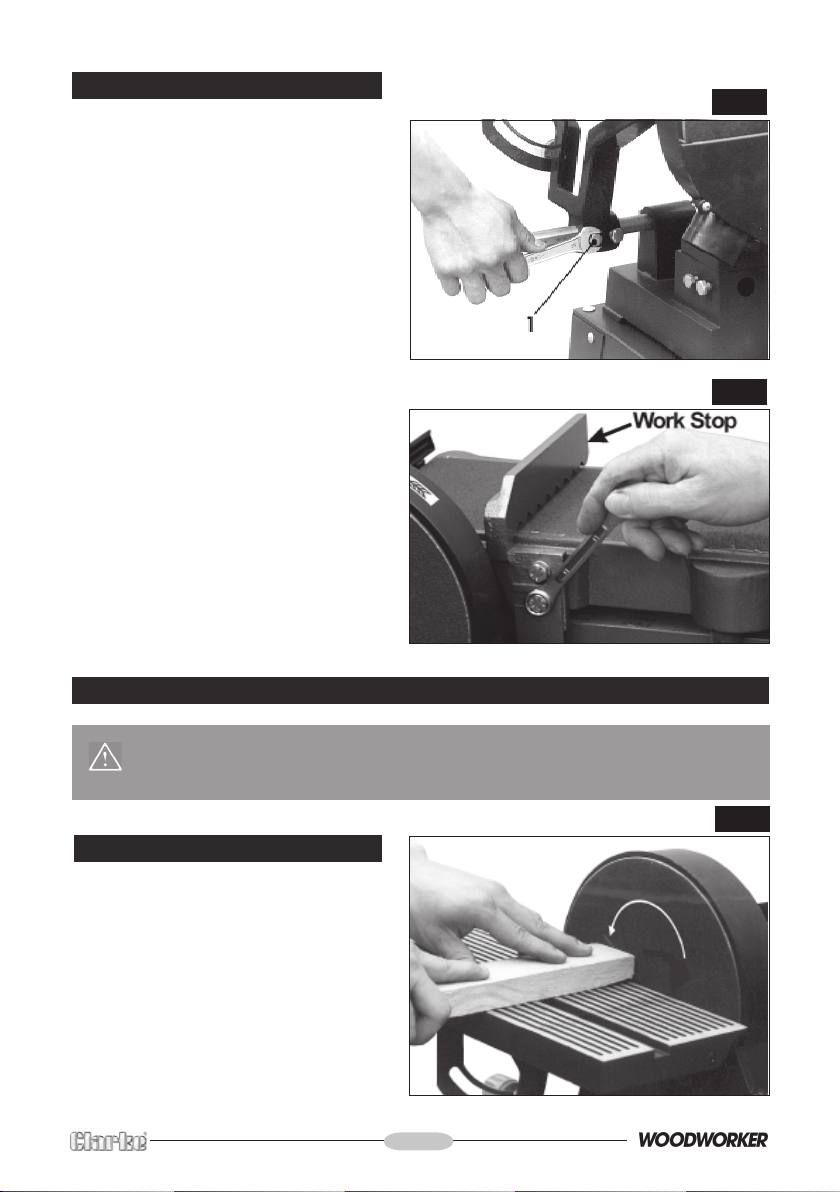
Slide the Table Support bar into the
mounting as shown in fig. 6 with the shorter
flat on the end of the bar - inwards. Tighten
the two securing screws.
Mount the table on the support bar, bring
to within 2mm of the belt and tighten the
securing screws (1, fig 6).
To ensure the table is square, proceed
as previously described for squaring the
table to the disc.
When using the table with the sanding
belt, remove the work stop from the belt
by removing the two securing bolts as
shown in fig. 7.
Ensure the screws are replaced and
tightened before use. The lower screw
also secures the Lower Belt Guard. Ensure
this is properly in place when tightening.
Ensure also, the flat washer is used with
the upper bolt.
ENSURE the work stop is relaced correctly
- see Using the Belt on page 10.
Fig. 6
Fig. 7
METHODS OF USE
WARNING! Always observe the proper safety precautions before use.
Remember, failure to observe these precautions could be extremely
hazardous.
A. Using the Disc
Check to ensure the table is no more
than 2mm from the disc, before switching
ON.
Hold the work firmly, as shown in fig. 8 and
ALWAYS hold the workpiece against the
left half of the disc. i.e. that half moving
downwards towards the table.
DO NOT exert too much pressure. A light
touch is all that is required.
- 9 -
Fig. 8
Page 10
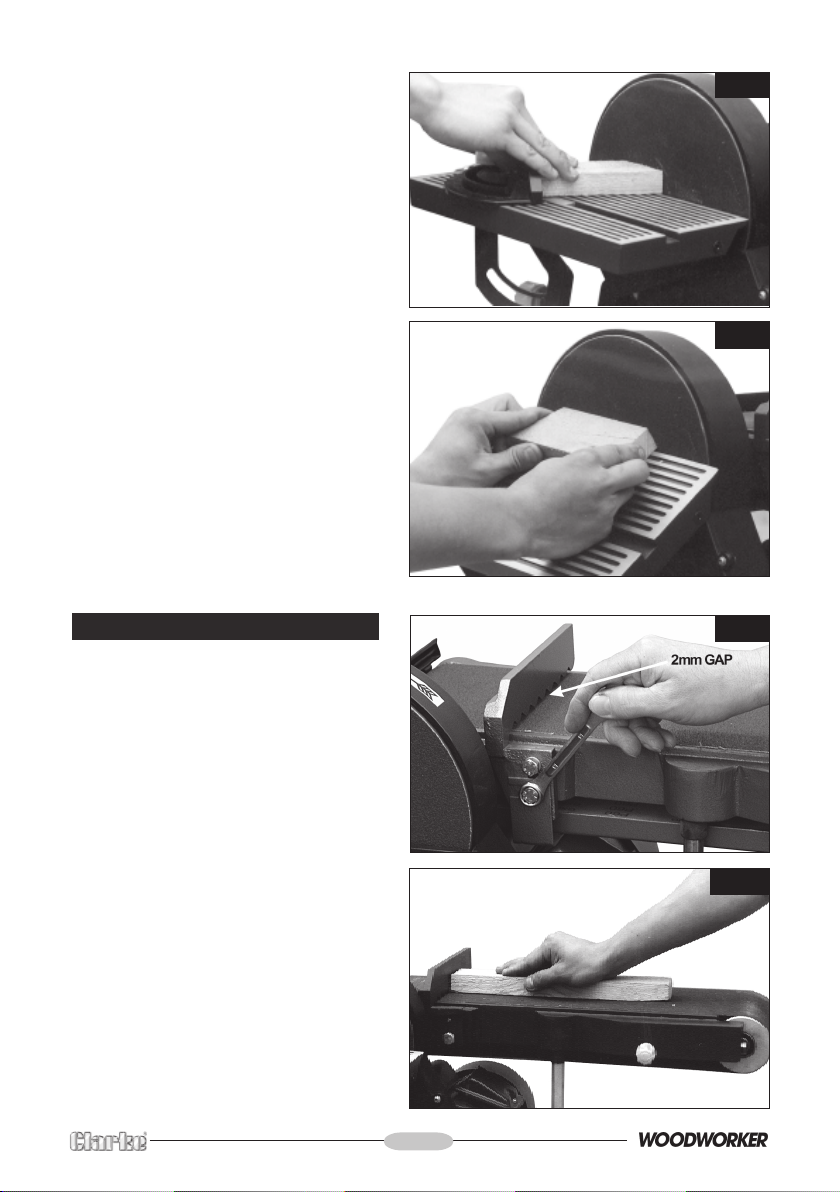
Fig. 8A shows the table being used in
conjunction with the Mitre Gauge.
Set the gauge to the angle you require
and hold the workpiece firmly against
the gauge, feeding it gently into the
disc.
Keep the workpiece in contact with the
left side of the disc as far as possible.
Fig. 8B shows the table set to an angle.
The mitre gauge may also be used with
this setup.
Angles up to 45o may be set.
If accuracy is required, check angle
using a suitable square or template.
Fig. 8A
Fig. 8B
B. Using the Belt
The Work Stop must be in place when
using the belt horizontally.
Bolt on as shown in Fig.9, ensuring the
flat washer is used between the inner
face of the fence and the body on the
upper bolt.
The lower bolt also secures the lower
blade guard.
When tightening the bolts, ensure a
gap of no more than 2mm exists
between the belt and the work stop,
as indicated.
The belt is used for long pieces, as shown
in Fig. 9A. The workpiece is held firmly
against the work stop.
DO NOT exert too much pressure - a light
touch is all that is required.
Fig. 9
Fig. 9A
- 10 -
Page 11
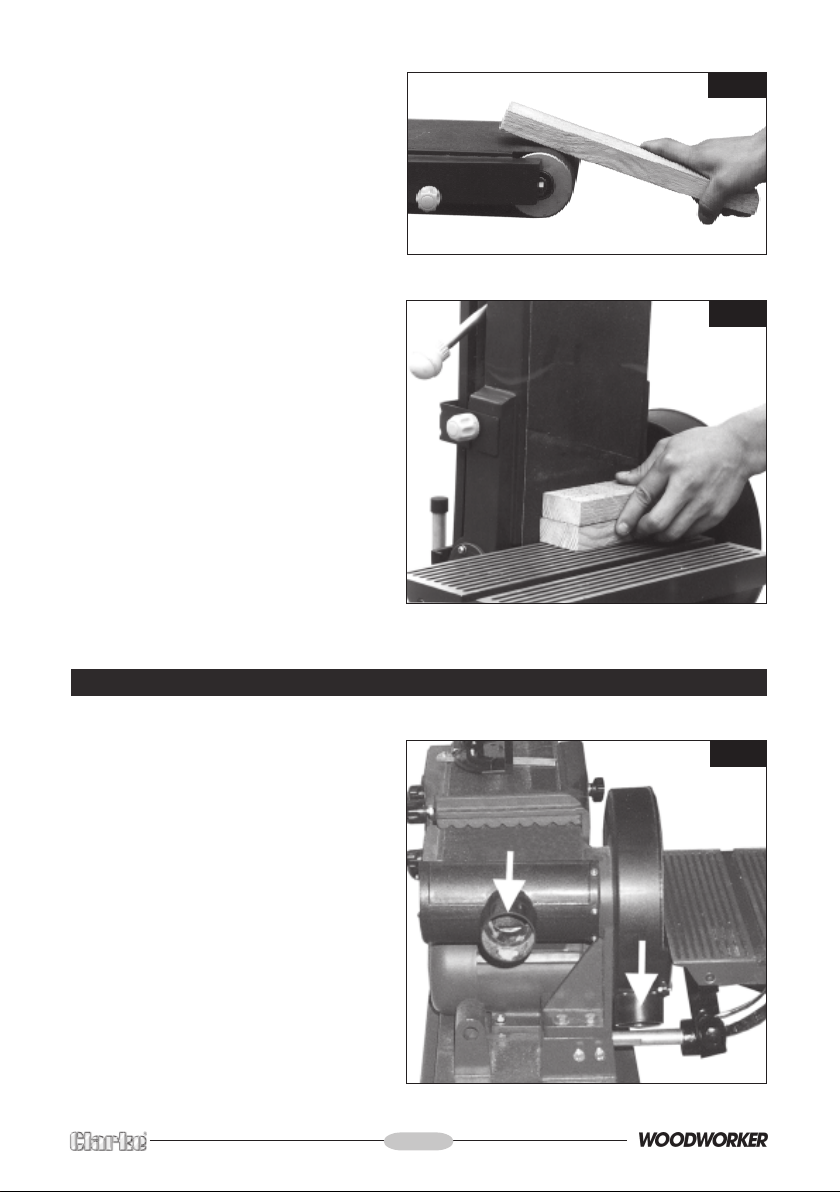
Curves may be sanded as shown in Fig.
9A
...or the belt used in the vertical position
as shown in Fig.9B.
NOTE: The work stop has been removed.
Fig. 9A
Fig. 9B
DUST EXTRACTION
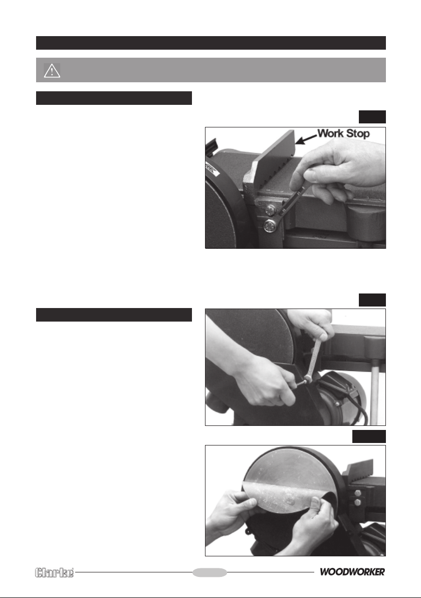
Provision is made for forced dust
extraction on both the disc AND belt.
The dust extraction outlets are shown in
Fig.10 and have an outside diameter
of 56mm (21/4”).
Connect a suitable hose to a vacuum
cleaner via a reducer, or Dust Extraction
device (see your Clarke dealer).
Fig. 10
- 11 -
Page 12
MAINTENANCE
CAUTION: Before carrying out any maintenance or servicing, ALWAYS ensure the
plug is disconnected from the mains supply.
A. Changing the Belt
1. Raise the table and secure in the vertical position.
2. Remove the lower Belt Cover, by
slackening the four securing screws
sufficiently for the cover to be
slipped off.
3. Remove the screw securing the dust
hand (or rear) mounting.
4. Slide the Belt Tension Lever fully
FORWARD. (As the Belt Arm is vertical,
this would be - UPWARDS).
The belt may now be slipped off and
replaced by a new one.
5. Tension the belt by sliding the tensioning lever backwards (downwards), then replace
the belt cover.
6. Proceed to check belt tracking, as described on page 7
B. Changing the Disc
Fig. 11
Fig. 12
1 Remove the disc side cover as shown
in Fig. 12, then peel off the disc.
2. Clean any excess adhesive from the
face of the disc, if any, and replace
with a new disc, ensuring it is firmly
attached.
3. When satisfied, replace cover.
Fig. 12A
- 12 -
Page 13
ACCESSORIES
Replacement Discs and Belts are available in packs of 5 from your local dealer.
Please quote the part numbers below.
A. 6” Replacement Belts (150 x 1219mm)
Grit size Part No.
Fine ..................................................... 6502098
Medium .............................................. 6501164
Coarse ............................................... 6502103
B. 9” Replacement Discs (230mm)
Grit size Part No.
Fine ..................................................... 6502099
Medium .............................................. 6501076
Coarse ............................................... 6502100
SPECIFICATIONS
Motor ................................................................ 230V 50Hz 1Ph
Power Rating ......................................... 750W (1HP)
Speed .................................................... 2850RPM
Input Current ......................................... 4Amps
Fuse Rating ...................................................... 13Amps
Belt Speed ....................................................... 5.6 M/s
Belt Size ............................................................ 150 x 1219mm (6x48in)
Disc Speed ....................................................... 1400RPM
Disc Size............................................................ 230mm (9in)
Gross Weight.................................................... 51.5kg
Model No. ........................................................ CS6-9C
Part No. ............................................................ 6500420
- 13 -
Page 14
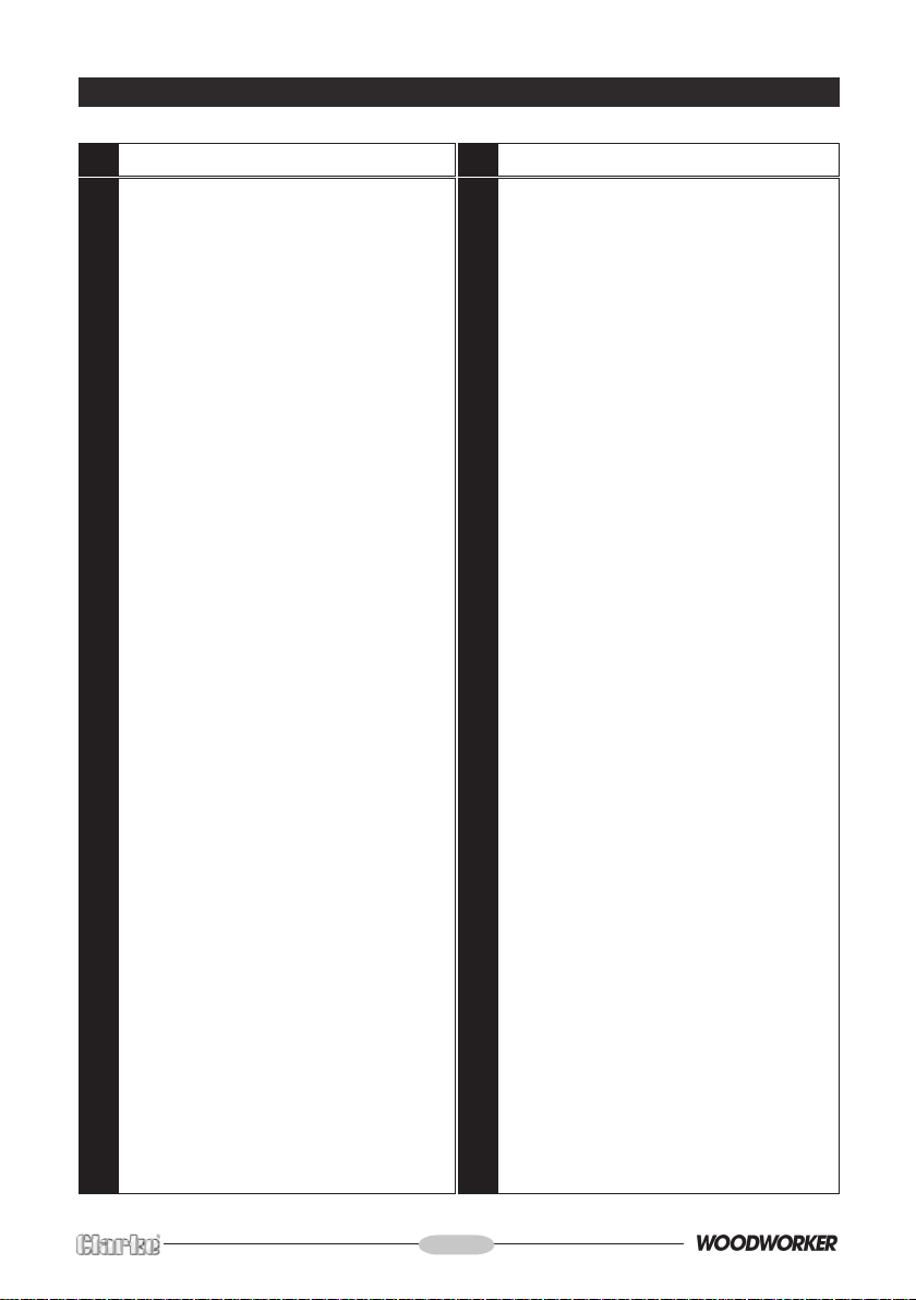
PARTS LIST
No. Description Part No. No.. Description Part No.
1 Rubber pad HTCS6901
2 Side plate HTCS6902
3 Bolt M8x12 HTCS6903
4 Nut M6 HTCS6904
5 Washer HTCS6905
6 Long plate HTCS6906
7 Bolt HTCS6907
8 Short plate HTCS6908
9 Nut M8 HTCS6909
10 Screw M4x8 HTCS6910
11 Switch box HTCS6911
12 Safety switch HTCS6912
13 Fixed plate HTCS6913
14 Button ring HTCS6914
15 Ball bearing 80201 HTCS6915
16 Roller shaft HTCS6916
17 Roller wheel HTCS6917
18 Sustain shaft HTCS6918
19 Spring pin 4x16 HTCS6919
20 Screw M5x8 HTCS6920
21 Spring HTCS6921
22 Shaft HTCS6922
23 Knob HTCS6923
24 Cover securing knob HTCS6924
25 Guard HTCS6925
26 Sanding belt HTCS6926
27 Screw M5x16 HTCS6927
28 Washer HTCS6928
29 Elastic washer HTCS6929
30 Adjustment plate HTCS6930
31 Nut M4 HTCS6931
32 Spring HTCS6932
33 Adjusting plate HTCS6933
34 Moving plate HTCS6934
35 Spring HTCS6935
36 Base HTCS6936
37 Plastic clip HTCS6937
38 Nut M16 HTCS6938
39 Support bolt HTCS6939
40 Rubber sleeve HTCS6940
41 Sand belt frame HTCS6941
42 Ball bearing 80102 HTCS6942
43 Screw M4x12 HTCS6943
44 Washer HTCS6944
45 Drive roller shaft HTCS6945
46 Key B5x28 HTCS6946
48 Dust extraction outlet cover HTCS6948
49 Screw M8x12 HTCS6949
50 Drive roller HTCS6950
51 Work stop HTCS6951
52 Flat Washer HTCS6952
53 Motor HTCS6953
54 Ball bearing 80103 HTCS6954
55 Button ring HTCS6955
56 Shaft cover HTCS6956
57 Screw HTCS6957
58 Bracket HTCS6958
59 Support shaft HTCS6959
60 Nut M6 HTCS6960
61 Screw M6x30 HTCS6961
62 Mitre gauge HTCS6962
65 Table HTCS6965
66 V-belt HTCS6966
67 Motor pulley HTCS6967
68 Pulley cover HTCS6968
69 Screw M5x16 HTCS6969
70 Screw M8x12 HTCS6970
71 Shaft pulley HTCS6971
72 Sand disc HTCS6972
73 Sand paper see Accessories
74 Screw M6x16 HTCS6974
75 Washer HTCS6975
76 Angle Gauge HTCS6976
77 Table support bracket HTCS6977
78 Pointer HTCS6978
79 Plug & cable HTCS6979
80 Bolt HTCS6980
81 Knob HTCS6681
82 Bearing cover HTCS6982
83 Knob HTCS6983
84 Bolt HTCS6984
85 Disc cover HTCS5985
86 Screw HTCS6986
- 14 -
Page 15
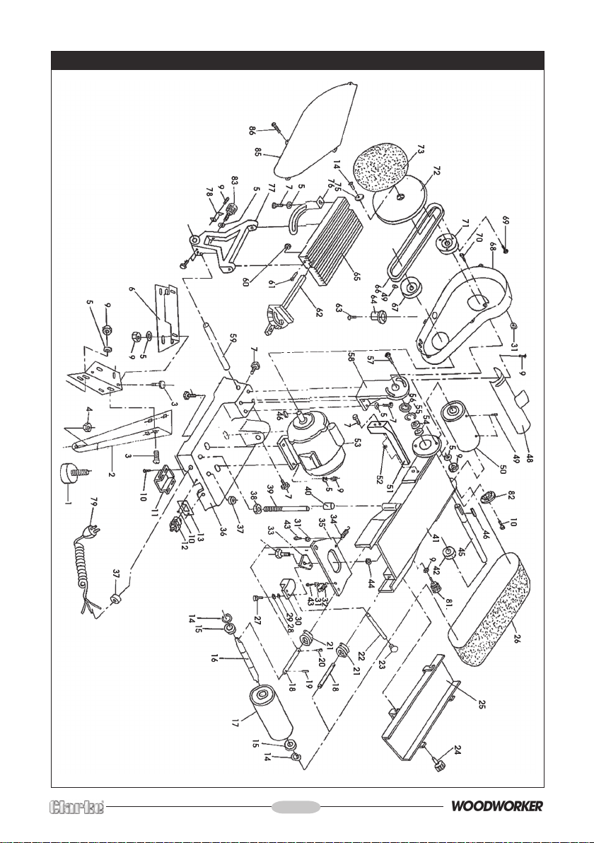
PARTS DIAGRAM
- 15 -
Page 16

 Loading...