


1200W VARIABLE SPEED ROUTER
MODEL NO: CR1C
PART NO: 6462072
OPERATION & MAINTENANCE
INSTRUCTIONS
01/11

INTRODUCTION
Thank you for purchasing this CLARKE 1200W Variable Speed Router.
Before attempting to use this product, please read this manual thoroughly and
follow the instructions carefully. In doing so you will ensure the safety of yourself
and that of others around you, and you can look forward to your purchase
giving you long and satisfactory service.
GUARANTEE
This product is guaranteed against faulty manufacture for a period of 12
months from the date of purchase. Please keep your receipt which will be
required as proof of purchase.
This guarantee is invalid if the product is found to have been abused or
tampered with in any way, or not used for the purpose for which it was
intended.
Faulty goods should be returned to their place of purchase, no product can
be returned to us without prior permission.
This guarantee does not effect your statutory rights.
IN THE BOX
• 1 x 1200 Watt Variable Speed Router
• 2 x Collet 8mm and 6.35mm (1/4") (one of which may be supplied
fitted in the router).
• 1 x Collet Nut
• 1 x Collet Spring
• 1 x Parallel Fence
• 2 x Parallel Fence Rods; 300mm x 8mm (Supplied with two M4.5mm x
10.0mm screws and washers for mounting the fence See page 9.)
• 1 x 18mm Guide Bush (Template Guide)
• 1 x Trammel Attachment
• 2 x M4.5 Plain Nuts
• 1 Collet Spanner
• 1 Reusable Cable Tie
2

TABLE OF CONTENTS
INTRODUCTION .....................................................................2
GUARANTEE ..........................................................................2
IN THE BOX ............................................................................2
TABLE OF CONTENTS ............................................................3
GENERAL SAFETY RULES .......................................................4
ELECTRICAL CONNECTIONS ................................................6
OVERVIEW ............................................................................7
BEFORE USE ...........................................................................8
FITTING THE GUIDES ..............................................................9
USING YOUR ROUTER ...........................................................10
ADJUSTMENTS .......................................................................11
ROUTER TIPS ..........................................................................13
TROUBLESHOOTING ..............................................................13
FITTING YOUR ROUTER TO A ROUTER TABLE ........................14
MAINTENANCE .....................................................................15
ENVIRONMENTAL PROTECTION ...........................................15
SPECIFICATIONS ...................................................................16
PARTS AND SERVICING ........................................................16
VIBRATION EMMISIONS .......................................................17
DECLARATION OF CONFORMITY ........................................19
3

GENERAL SAFETY RULES
WORK AREA
1. Keep the work area clean and well lit. Cluttered and dark areas invite
accidents.
2.
Do not operate power tools in explosive atmospheres, such as in the
presence of
may ignite the dust or fumes.
3.
Keep children and bystanders away while operating a power tool.
Distractions can cause you to lose control.
ELECTRICAL SAFETY
1. Power tool plugs must match the outlet. Never modify the plug in any way.
Do not use adapter plugs with earthed (grounded) power tools. Unmodified
plugs and matching outlets will reduce the risk of electric shock.
2.
Do not expose power tools to rain or wet conditions. Water entering a power
tool will increase the risk of electric shock.
3.
Do not abuse the cord. Never use the cord for carrying, pulling or
unplugging the power tool. Keep the cord away from heat, oil, sharp edges
or moving parts.
4. When operating a power tool outdoors, use an extension cord suitable for
outdoor use. Use of a cord suitable for outdoor use reduces the risk of electric
shock.
flammable liquids, gases or dust. Power tools create sparks which
Damaged or entangled cords increase the risk of electric shock.
PERSONAL SAFETY
1. Stay alert, watch what you are doing and use common sense when
operating a power tool.
influence of drugs, alcohol or medication. A moment of inattention while operating
power tools may result in personal injury.
2.
Use safety equipment. Always wear eye protection. Safety equipment such as
dust mask, non-skid safety shoes, hard hat, or hearing protection used for
appropriate conditions will reduce personal injuries.
3.
Avoid accidental starting. Ensure the switch is in the off position before plugging
in. Carrying power tools with your finger on the switch or plugging in power tools that
have the switch on invites accidents.
Remove any adjusting key or wrench before turning the power tool on. A
4.
wrench or a key left attached to a rotating part of the power tool may result in
personal injury.
5.
Do not overreach. Keep proper footing and balance at all times. This enables
better control of the power tool in unexpected situations.
Do not use a power tool while you are tired or under the
4

6. Dress properly. Do not wear loose clothing or jewellery. Keep your hair, clothing
and gloves away from moving parts. Loose clothes, jewellery or long hair can be
caught in moving parts.
POWER TOOL USE AND CARE
1. Do not force the power tool. Use the correct power tool for your application. The
correct power tool will do the job better and safer at the rate which it was designed.
2.
Do not use the power tool if the switch does not turn it on and off. Any power
tool that cannot be controlled with the switch is dangerous and must be repaired.
3.
Disconnect the plug from the power source before making any
adjustments, changing accessories, or storing power tools.
safety measures reduce the risk of starting the power tool accidentally.
4.
Store idle tools out of the reach of children and do not allow persons
unfamiliar with the power tool or these instructions to operate the power
Power tools are dangerous in the hands of untrained users.
tool.
5. Maintain power tools. Check for misalignment or binding of moving parts,
breakage of parts and any other condition that may affect the power tools
operation. If damaged, have the power tool repaired before use. Many accidents
are caused by poorly maintained power tools.
6.
Keep cutting tools sharp and clean. Poorly maintained cutting tools with sharp
cutting edges are less likely to bind and are easier to control.
7.
Use the power tool, accessories and tool bits etc., in accordance with
these instructions. Use of the power tool for operations different from intended
could result in a hazardous situation.
Such preventive
SERVICE
1. Have your power tool serviced by a qualified repair person using only
identical replacement parts. This will ensure that the safety of the power tool is
maintained.
5

ELECTRICAL CONNECTIONS
Connect the mains lead to a standard, 230 Volt (50Hz) electrical supply
through an approved 13 amp BS 1363 plug, or a suitably fused isolator switch.
THIS APPLIANCE IS DOUBLE INSULATED
The wires in the mains lead are coloured in accordance with the following
code:
Blue - Neutral
Brown - Live
As the colours of the flexible lead of this appliance may not correspond with
the coloured markings identifying terminals in your plug proceed as follows:
• No connection should be made to the earth terminal .
• Connect BROWN cord to terminal marked with a letter “L” or
coloured RED.
• Connect BLUE cord to terminal marked with a letter “N” or coloured
BLACK.
If this appliance is fitted with a plug which is moulded onto the electric cable
(i.e. non-rewireable) please note:
1. The plug must be thrown away if it is cut from the electric cable. There is a
danger of electric shock if it is subsequently inserted into a socket outlet.
2. Never use the plug without the fuse cover fitted.
3. When replacing a detachable fuse carrier, ensure the correct replacement
is used (as indicated by marking or colour code).
4. Replacement fuse covers can be obtained from your local dealer or most
electrical stockists.
FUSE RATING
• The fuse in the plug must be replaced with one of the same rating
and this replacement must be ASTA approved to BS1362.
• We strongly recommend that this machine is connected to the
mains supply via a Residual Current Device (RCD)
If in any doubt, consult a qualified electrician. DO NOT attempt any repairs
yourself.
6

OVERVIEW
1
2
3
4
5
6
7
8
9
10
11
NO. DESCRIPTION PART NUMBER NO. DESCRIPTION PART NUMBER
1 Speed Dial KPCR1C01 7 Multi-stop Turret KPCR1C07
2 Safety Button KPCR1C02 8 Depth Stop KPCR1C08
3 Trigger Switch (Rear) KPCR1C03 9 Depth Stop Lock KPCR1C09
4 Spindle Lock KPCR1C04 10 Plunge Lock Lever
5
Parallel Guide
Locking Screws
6 Collet Nut KPCR1C06
KPCR1C05 11 Micro Adjustment
(Rear)
Dial
7
KPCR1C10
KPCR1C11

BEFORE USE
WARNING: MAKE SURE THAT THE ROUTER IS SWITCHED OFF AND
UNPLUGGED FROM THE MAINS SUPPLY BEFORE FITTING OR REMOVING
ANY ACCESSORIES.
INSTALLING AND CHANGING ROUTER BITS
1. Rotate spindle whilst pushing the
spindle lock inwards until spindle is
locked, (hold the spindle lock on).
2. Using the wrench supplied, loosen
the collet nut a few turns and
remove bit if fitted.
3. Insert new bit and tighten collet
nut, release spindle lock.
IMPORTANT: At least two thirds of the
bit shank should be located inside the collet.
WARNING: NEVER TIGHTEN THE COLLET NUT WITHOUT A ROUTER BIT
INSERTED
FITTING THE DUST EXTRACTION COVER
1. Fit the dust extraction cover to the
router as shown.
2. Use the screws provided to secure
the dust extraction cover.
8
FITTING THE GUIDES
The tool is supplied with three guides,
• Parallel fence guide: primarily used for straight cuts, when
chamfering or grooving.
• Template guide: Fitted when the tool is used in conjunction with
templates.
• Trammel attachment: Used to move the router in an arc around a
selected pivot point.
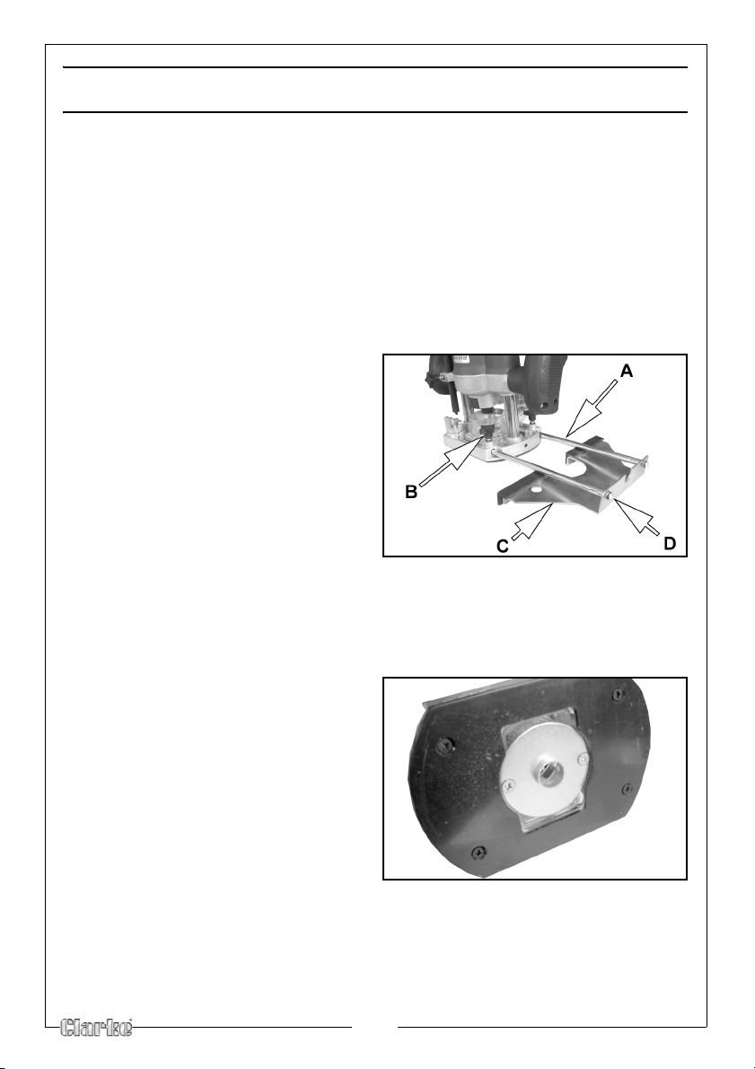
FITTING THE PARALLEL GUIDE FENCE
1. Connect the rods (A) to the guide
body (C), securing with the screws
(D) provided.
2. Fit the assembled guide to the
router as shown on the right.
3. Secure using the parallel guide
locking screws (B).
The parallel guide allows the user to
follow a straight edge with accuracy.
It is always advisable to make a trial
cut in a piece similar to that to be worked where possible.
FITTING THE TEMPLATE GUIDE
The template guide allows the user to
duplicate a particular shape, that
shape being used as a template.
NOTE: The template guide can only
be used if the dust extraction
cover is fitted.
1. With the tool upside down,
remove the two screws securing
the dust extraction collar in place.
2. Fit the template guide with the
raised boss facing the workpiece.
3. Secure using the two screws.
9

FITTING THE TRAMMEL ATTACHMENT
Screw
Wing Nut
Piviot Point
Rod
1. Remove one of the rods from the parallel guide and insert it into position on
the router. Secure in place using the parallel guide locking screws.
2. Loosen the wing nut on the
trammel attachment and slide
the attachment on to the parallel
guide rod as shown.
3. Adjust the height of the pivot
point by turning the screw.
4. Tighten the wing nut to lock the
pivot point in place and the
trammel attachment to the rod.
USING YOUR ROUTER
When using the router, there are some points to bear in mind which will ensure
that the best results are achieved.
SWITCHING THE ROUTER ON/OFF
1. Grip the tool with both hands,
ensuring the power on/off switch
is in the right hand.
2. Push and hold the safety button,
and pull the trigger switch.
• Allow the motor to reach full
speed before use.
3. To stop the router, simply release
the trigger.
TO PLUNGE THE ROUTER
1. Place router on the workpiece with the cutter in the position to be cut.
10

2. Press down on both handles to
the required depth, pushing the
bit into the work piece.
• The depth stop should be pre-
set (See “Setting The Depth Of
Cut” on page 11.)
3. Pull the plunge lock lever towards
the handle to lock the body in
position.
4. To raise the tool, push the plunge
lock lever away from the handle and allow the body to rise out of the
workpiece.
WARNING: ENSURE THAT THE TOOL HAS REACHED OPERATING SPEED
BEFORE BEGINNING ANY CUTTING OPERATIONS.
ADJUSTING THE SPEED
The tool speed can be adjusted to
suit the bit diameter and the type of
material being cut.
Generally, the larger the diameter of
the bit, the slower the tool speed
should be.
• Rotate the speed selector
wheel to adjust the speed
setting from 1 to 7.
It is advisableto make practice cuts
on a piece of scrap timber to determine the best speed.
ADJUSTMENTS
SETTING THE DEPTH OF CUT
With the appropriate bit installed, proceed as follows:
1. Fit a suitable router bit and place the tool on a flat surface.
11

2. Release the plunge lock lever and
Depth Stop
Depth Stop
Micro
Adjustment
Dial
Lock
lower the tool body until the bit just
touches the flat surface, then apply
the plunge lock.
3. Slacken the depth stop lock and
lower the depth stop rod, until the
rod touches the multi-stop turret at its
lowest setting.
4. Make a note of the position
indicated on the scale.
5. Raise the height of the depth stop
rod by the depth you want to cut
into the wood. Each mark on the
scale is equal to 1mm.
6. Tighten the depth stop lock.
7. Fine adjustment can be made by
turning the micro adjustment dial. A
full turn is equal to 1mm.
CAUTION: TO PREVENT DAMAGE TO THE MOTOR OR DIFFICULTY
CONTROLLING THE TOOL, THE DEPTH OF CUT SHOULD BE LIMITED TO
10MM AT ONE PASS. IF YOU REQUIRE MORE THAN 10MM MAKE SEVERAL
PASSES WITH PROGRESSIVELY DEEPER SETTINGS.
USING THE MULTI-STOP TURRET
The multi-stop turret can be used to assist in making multiple passes. Using the
turret in this manner removes the necessity for resetting the adjuster rod for
each pass. Each stop on the turret is approx. 3mm.
1. With the total depth set and the
router raised fully, turn the turret to
a higher step to restrict the depth
of cut.
2. Make the first pass on the wood.
3. Rotate the turret to a lower setting
and make the second pass.
4. Repeat this until the final cut is
made.
12

ROUTER TIPS
DIRECTION OF FEED
Remember that the direction the
cutter is fed into the wood must
always be against the direction of
rotation as shown in the diagram on
the right.
This ensures a quality finish and also
ensures that the cutting action pulls
the side fence or guide bearing into
the wood.
FEED RATE
The optimum speed at which the bit is fed into the workpiece will come with
experience.
• Feeding too fast may cause a poor quality cut or damage the
motor.
• Move too slowly and the bit may leave burn marks on the face of
the wood.
The proper feed rate to use depends on the bit size, the material being cut,
the depth of the cut and the speed selected.
It is advisable to make practice cuts on a piece of scrap timber to determine
the best feed rate.
TROUBLESHOOTING
Problem Reason Solution
Router is overheating. Ventilation holes are
blocked / Machine is dirty.
Router is overloading. Do not use put excessive pres-
Excessive sparking. Worn Brushes. Contact you nearest Clarke
Router does not operate
when switched on.
Fuse has blown. Replace fuse.
13
Make sure the ventilation
holes are clear.
sure on the cutter.
dealer for repair.

FITTING YOUR ROUTER TO A ROUTER TABLE
This unit shown fitted to the Clarke CRT1 Router Table
A router table allows the work to be passed over the router, rather than
passing the router over the work. This makes working with smaller objects
easier. A router table may be fitted with a fence, fingerboards and other workguiding accessories to make the operation safer and more accurate.
• We recommend the Clarke CRT1 available from your local Clarke
dealer.
1. With the router unplugged, fit the
router to the router table as
shown in the router table user
guide.
2. Push and hold the safety button,
and pull the trigger switch on the
router.
3. Lock the trigger switch in the ON
postion using the re-useable
cable tie supplied.
CAUTION: ONLY USE THE CABLE TIE IF THE ROUTER IS FITTED TO THE
ROUTER TABLE.
4. Plug the router into the router table switch and follow the instructions in the
router table user guide.
14

MAINTENANCE
There are no user serviceable parts in this router, all servicing should be carried
out by your nearest Clarke dealer.
CLEANING
• To ensure the best performance from the router, it must be kept
clean.
• To reduce fire hazard, keep the cooling vents free of debris.
GENERAL MAINTENANCE
• Make sure that all nuts, bolts and screws are tight and secure.
• Always have any damaged or worn parts repaired, or replaced.
• Always have your router inspected and maintained by qualified
service personnel. Do not attempt to repair the router unless you are
qualified to do so.
STORAGE
• Make sure that the router has been thoroughly cleaned before
storing it in a clean, dry place out of the reach of children.
ENVIRONMENTAL PROTECTION
Do not dispose of this product with general household waste. All
tools, accessories and packaging should be sorted, taken to a
recycling centre and disposed of according to the laws governing
Waste Electrical and Electronic Equipment.
15

SPECIFICATIONS
For Parts & Servicing, please contact your nearest dealer, or
CLARKE International, on one of the following numbers.
PARTS & SERVICE TEL: 020 8988 7400
PARTS & SERVICE FAX: 020 8558 3622
or e-mail as follows:
PARTS: Parts@clarkeinternational.com
SERVICE: Service@clarkeinternational.com
Electric Supply 230V 50Hz
Motor Power Rating 1200W
No Load Speed 13700/30000 RPM
Maximum Plunge Depth 50mm (Without Extraction Spout)
42mm (Extraction Spout Fitted)
Collet Size 2 Supplied (8mm & 6.35mm)
Dust extraction Adaptor Port Size 32 mm
Net Weight 4 kg
Guaranteed Sound Power (L
Vibration Levels
Specifications are correct at the time of going to print. However, CLARKE International reserve the
right to change specifications at any time without prior notice.
wa dB) 97 dB
6.23m/s
2
Uncertanty value K (1.5)
PARTS AND SERVICING
There are no user serviceable parts, all servicing and repairs should be carried
out by your nearest Clarke dealer.
16

VIBRATION EMMISIONS
Employers are advised to refer to the HSE publication “Guide for Employers”.
All hand held power tools vibrate to some extent, and this vibration is
transmitted to the operator via the handle, or hand used to steady the tool.
Vibration from about 2 to 1500 herz is potentially damaging and is most
hazardous in the range from about 5 to 20 hertz.
Operators who are regularly exposed to vibration may suffer from Hand Arm
Vibration Syndrome (HAVS), which includes ‘dead hand’, ‘dead finger’, and
‘white finger’. These are painful conditions and are widespread in industries
where vibrating tools are used.
The health risk depends upon the vibration level and the length of time of
exposure to it……in effect, a daily vibration dose.
Tools are tested using specialised equipment, to approximate the vibration
level generated under normal, acceptable operating conditions for the tool in
question. For example, a grinder used at 45° on mild steel plate, or a sander
on soft wood in a horizontal plane etc.
These tests produce a value ‘a’, expressed in metres per second per second,
which represents the average vibration level of all tests taken, in three axes
where necessary, and a second figure ‘K’, which represents the uncertainty
factor, i.e. a value in excess of ‘a’, to which the tool could vibrate under
normal conditions. These values appear in the specification panel below.
Model Number CR1C
Description Router
Declared vibration emission value in accordance with EN12096
Measured vibration emission value - a:
Uncertainty Value - k.
Value determined according to EN28622-1
2
‘a’ values in excess of 2.5 m/s
are considered hazardous when used for
6.23 m/s
1.5
prolonged periods. A tool with a vibration value of 2.8 m/s
2
2
may be used for
up to 8 hours (cumulative) per day, whereas a tool with a value of 11.2 m/s
may be used for ½ hour per day only.
17
2

The graph on the right shows the
vibration value against the maximum
time the respective tool may be
used, per day.
The uncertainty factor should also be
taken into account when assessing a
risk. The two figures ‘a’ and ‘K’ may
be added together and the resultant
value used to assess the risk.
It should be noted that if a tool is
used under abnormal, or unusual
conditions, then the vibration level
could possibly increase significantly. Users must always take this into account
and make their own risk assessment, using the graph above as a reference.
Some tools with a high vibration value, such as impact wrenches, are
generally used for a few seconds at a time, therefore the cumulative time
may only be in the order of a few minutes per day. Nevertheless, the
cumulative effect, particularly when added to that of other hand held power
tools that may be used, must always be taken into account when the total
daily dose rate is determined.
18

DECLARATION OF CONFORMITY
19

 Loading...