

Page 1

AIR PRESSURISED PAINT FEED
AIR PRESSURISED PAINT FEED
CONTAINER
CONTAINER
Model Nos:
CPP5 • CPP11 • CPP30 • CPP40
OPERATING & MAINTENANCE
INSTRUCTIONS
1106
Page 2

Parts List - CPP 30 & 40
Please read these instructions carefully before using the Paint Pot
Thank you for purchasing this CLARKE Air Pressurised Paint Feed Container.
Before using the device, please read this manual thoroughly and carefully
follow all instructions given. This is for your own safety and that of others around
you, and is also to help you achieve long and trouble free service from your
new product.
CLARKE GUARANTEE
This CLARKE product is guaranteed against faulty manufacture for a period
of 12 months from the date of purchase. Please keep your receipt as proof
of purchase.
This guarantee is invalid if the product is found to have been abused or
tampered with in any way, or not used for the purpose for which it was
intended.
Faulty goods should be returned to their place of purchase, no product
can be returned to us without prior permission.
This guarantee does not affect your statutory rights.
SPECIFICATIONS
CPP5 CPP12 CPP30 CPP40
Inner Container capacity 3.25L 9.25L 24.5L 34L
Outer Container capacity 4.2L 11.7L 31.2L 43.4L
Fluid Type Oil/Solvent based paints
Maximum Operating Pressure 3bar 3bar 3bar 3bar
Absolute Maximum Pressure 5.5bar 5.5bar 5.5bar 5.5bar
Air Hose Connection 1/4”BSP 1/4”BSP 1/4”BSP 1/4”BSP
Liquid Hose Connection 3/8” BSP 3/8” BSP 3/8” BSP 3/8” BSP
Weight unpacked 5.85kg 14.5kg 24kg 26kg
No. Description Part No:
1 Container CPP30 1 KLCPP3001
1 Container CPP40 1 KLCPP4001
2 Lid assembly 1 KLCPP3002
3 Inner Container CPP30 1 KLCPP3003
3 Inner Container CPP40 1 KLCPP4003
4 Gasket 1 KLCPP3004
5 Guard 1 KLCPP3005
6 Hex. Nut 2 KLCPP3006
7 Air Exhaust Valve 1 KLCPP3007
8 O-ring 1 KLCPP3008
9 Adapter 1 KLCPP3009
10 Air inlet adapter 2 KLCPP3010
10a Air adapter 2 KLCPP3010A
11 Tee Piece 1 KLCPP3011
12 Air Outlet Cock 1 KLCPP3012
13 Nut 1 KLCPP3013
14 Air Outlet 1 KLCPP3014
15 Air inlet Cock 1 KLCPP3015
16 Pressure Regulator 1 KLCPP3016
17 Bolt 1 KLCPP3017
18 Handle 1 KLCPP3018
19 Hex. Nut 5 KLCPP3019
20 Handle Lever 1 KLCPP3020
21 Bolt 1 KLCPP3021
22 Bolt 1 KLCPP3022
23 Cap Screw 1 KLCPP3023
24 Sealing Ring 1 KLCPP3024
No. Description Part No:
25 Connecting ring 1 KLCPP3025
26 O-ring 2 KLCPP3026
27 Guide Bush 1 KLCPP3027
28 Seal Ring 1 KLCPP3028
29 Pressure Relief valve 1 KLCPP3029
35 Fluid outlet Cock 2 KLCPP3035
36 Fluid Outlet Adapter 1 KLCPP3036
37 Pressure Gauge 1 KLCPP3037
38 Agitator Rod CPP30 1 KLCPP3038
38 Agitator Rod CPP40 1 KLCPP4038
39 Hex. Nut 1 KLCPP3039
40 Agitator 1 KLCPP3040
41 Swing Bolt 4 KLCPP3041
42 Washer 4 KLCPP3042
43 Wing Nut 4 KLCPP3043
44 Washer 4 KLCPP3044
45 Caster 4 KLCPP3045
46 C-Snap Ring 8 KLCPP3046
47 Cotter Pin 4 KLCPP3047
48 Fluid tube CPP30 1 KLCPP3048
48 Fluid Tube CPP40 1 KLCPP4048
49 Fluid Pick-Up 1 KLCPP3049
50 Filter Support 1 KLCPP3050
51 Filter 1 KLCPP3051
52 Snap Ring 1 KLCPP3052
53 Spanner 1 KLCPP3053
54 Air flow guide 1 KLCPP3054
2
11
Page 3

Parts Diagram - CPP 30 & 40
SAFETY PRECAUTIONS
1. ALWAYS keep the unit perfectly clean. This will not only prolong its life, but will
also ensure you get the best results.
2. NEVER exceed an air pressure supply of 80psi to the product.
3. NEVER attempt to adjust the safety valve
4. NEVER tamper with the product or modify in any way, as this could prove to
be dangerous and will invalidate the guarantee.
5. ONLY use the product for the purpose for which it is intended,
6. ALWAYS wear approved impact resistant SAFETY GOGGLES. (Eye glasses are
NOT safety glasses), and a FACE MASK
7. DO NOT remove any labels. Damaged labels should be replaced.
AIR SUPPLY
WARNING
Compressed air can be dangerous.
Ensure that you are thoroughly
familiar with all precautions relating
to the use of compressors and
compressed air supply.
Air pressure supply to the container should not be greater than 80psi. Higher pressure and
unclean air, will shorten the tools’ life because of faster wear, and could be a safety hazard.
Water in the air line will also cause damage. Ensure it is properly maintained at all times.
The recommended procedure to connect this product to an air supply, is shown below. A
filter/regulator should always be placed in line with the supply and the paint pot.
The air inlet used for connecting air supply, has a standard ¼” BSP thread.
Line pressure, or hose inside diameter, should be increased to compensate for unusually
long air hoses (over 10m). Minimum hose diameter should be 6mm (¼") ID., and fittings
should have the same inside dimensions.
10
3
Page 4
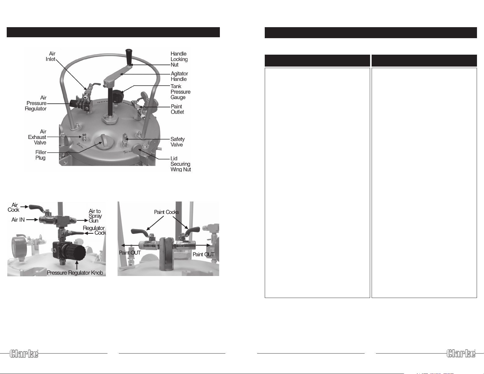
FEATURES
Parts List - CPP 11
Fig.1
Fig.2 Fig.3
The illustration above is of a CPP30, but components of other models are similar.
No. Description Part No:
1 Container 1 KLCPP1101
1a Inner Container 1 KLCPP1101a
2 Lid Assy 1 KLCPP1102
3 Gasket 1 KLCPP1103
4 Bolt 1 KLCPP1104
5 Handle 1 KLCPP1105
6 Nut Hex 1 KLCPP1106
7 Hand Lever 1 KLCPP1107
8 Bolt 1 KLCPP1108
9 Connecting Ring 2 KLCPP1109
10 O-Ring 2 KLCPP1110
11 Guide Bush 1 KLCPP1111
12 Seal Ring 1 KLCPP1112
13 Screw bolt 2 KLCPP11013
14 Guard 1 KLCPP1114
15 Hexagon nut 2 KLCPP1115
16 Adapter 1 KLCPP1116
17 Fluid Outlet adapter 1 KLCPP1117
18 Air Inlet Adapter 2 KLCPP1118
18a Adapter 1 KLCPP1118a
19 Air Cock 1 KLCPP1119
20 Pressure Regulator 1 KLCPP1120
21 Tee Piece 1 KLCPP1121
No. Description Part No:
22 Pressure gauge 1 KLCPP1122
29 Pressure Relief Valve 1 KLCPP1129
30 Adapter 1 KLCPP1130
31 O-ring 1 KLCPP1131
32 Air Exhaust Valve 1 KLCPP1132
33 Agitating rod 1 KLCPP1133
34 Hex. Nut 1 KLCPP1134
35 Agitator 1 KLCPP1135
36 Screw 1 KLCPP11036
37 Fluid Tube 1 KLCPP1137
38 Pick-Up 1 KLCPP1138
39 Filter Support 1 KLCPP1139
40 Filter 1 KLCPP1140
41 Snap ring 1 KLCPP1141
42 Swing bolt 4 KLCPP1142
43 Washer 4 KLCPP1143
44 Wing Nut 4 KLCPP1144
45 Nut 4 KLCPP1145
46 Washer 4 KLCPP1146
47 Caster 4 KLCPP1147
48 Spanner 4 KLCPP1148
49 C-Snap Ring 8 KLCPP1149
This Paint Feed Container is designed primarily for use in spraying oil and solvent
based paint.
Clarke International provides a range of Spray Guns which may be used with
these Feed Containers. Please see your local dealer for the HVLP and PRO Ranges.
4
9
Page 5

Parts Diagram - CPP 11
8
METHOD OF OPERATION
Prior to use, ensure the casters are properly screwed to their housings where appropriate
WARNING!
ALWAYS check to ensure the container is NOT under pressure, by checking the
pressure gauge and opening the air exhaust valve - turn the knurled ring nut
anticlockwise. Tighten the ring nut once again once all air is exhausted.
1. Fill the container with paint as follows:
• Undo each lid securing wing nut and swing the bolts out of the way.
• Lift off the lid.
• Fill the inner container with paint.
NOTE: It is permissible to fill the container itself, but we strongly recommend the
inner container be used at all times, as it is easier to clean.
• Replace the lid, ensuring the wing nuts are tightened progressively.
NOTE: Models CPP 30 and CPP40 are provided with filler plugs in the lid. These may
be used if preferred, but take care to comply with all precautions before undoing
2. Connect the air supply hose to the air inlet.
NOTE: See notes on Air Supply on page 4.
3. Connect the air hose from the spray gun, to the air outlet.
4. Connect the paint hose from the spray gun to the paint outlet.
5. Ensure the pressure regulator knob is turned fully anticlockwise, then turn ON
the air supply from compressor/air supply to the paint pot.
Where necessary, turn ON the air inlet cock at the cylinder, followed by the
pressure regulator cock.
6. Turn the pressure regulator knob slowly clockwise to pressurise the container.
Working pressure will depend upon the consistency of the medium, but must
NEVER exceed 3bar. If the medium is sluggish at this pressure, then it is of too
thick consistancy, and should not be sprayed.
7. Turn ON the air outlet cock.
8. Turn ON the paint outlet cock.
9. Finally, make adjustment
to the spray pattern
according to the spray
gun manufacturers
instructions.
The paint should be agitated
at regular intervals during use
to ensure consistancy and
avoid colour difference due
to the paint settling.The CPP5
may be shaken gently.
A typical configuration is shown in Fig.4.
Fig.4
5
Page 6

MAINTENANCE
It is important to clean the complete unit thoroughly at the end of any operation.
1. Turn OFF air to the container.
2. Turn the air exhaust valve knurled ring nut anticlockwise and allow the
container to completely depressurise.
3. Loosen all lid wing nut securing nuts, swing back the bolts and move the lid so
that it rests at one side of the container.
4. Hold the spray gun and hose above the level of the unit and pull the spray
gun trigger to allow paint in the hose to drain back into the container. The
paint cock should be open (where fitted).
5. Empty the container of paint, then clean it thoroughly with solvent or white
spirits etc., depending upon the type of paint being sprayed.
Clean and dry all components that have come into contact with paint agitator etc.
6. With the container and other components cleaned thoroughly, pour clean
solvent or other cleaner, into the container.
7. Replace the lid and tighten the wing nuts - progressively.
8. Turn ON the air to the container and pull the spray gun trigger. Keep it pressed
until only clean solvent or other cleaner is ejected from the spray gun.
9. Repeat steps 1 - 4 to allow solvent or other cleaner to drain back into the
container.
10 Finally empty the container and dry all components thoroughly,
Store in a clean dry place, with all cocks closed, and the lid loose.
Periodically, pressurise the container to 5.5bar in order to test the safety valve.
If it does not blow off at this pressure, do not use the appliance...have the Pressure
Relief Valve replaced.
Parts List & Diagram - CPP 5
PARTS & SERVICE CONTACTS
For Spare Parts and Service, please contact your nearest dealer,
or CLARKE International, on one of the following numbers.
PARTS & SERVICE TEL: 020 8988 7400
PARTS & SERVICE FAX: 020 8558 3622
or e-mail as follows:
PARTS: Parts@clarkeinternational.com
SERVICE: Service@clarkeinternational.com
6
No. Description Part No:
1 Container 1 KLCPP501
1a Inner Container 1 KLCPP501a
2 Lid Assy. 1 KLCPP502
3 Handle 1 KLCPP503
4 Gasket 1 KLCPP504
5 Fluid Tube 1 KLCPP505
6 Swing Bolt 1 KLCPP506
7 Washer 4 KLCPP507
8 Wing Nut 4 KLCPP508
9 Pressure Regulator 4 KLCPP509
10 Pressure Gauge 1 KLCPP510
11 Adapter - Air Inlet 1 KLCPP511
No. Description Part No:
12 Fluid Outlet 2 KLCPP512
13 Fluid Outlet Adapter 1 KLCPP513
14 Air Exhaust Valve 1 KLCPP514
15 O-Ring 1 KLCPP515
16 Adapter 1 KLCPP516
22 Pressure Relief Vlv 1 KLCPP522
23 Air Flow Guide 1 KLCPP523
24 Nut 1 KLCPP524
25 Cotter Pin 4 KLCPP525
26 Snap Ring 8 KLCPP526
27 Adapter Post 1 KLCPP527
7
 Loading...