

Page 1

PETROL COMPACTOR PLATE
MODEL NO: CPCP1
PART NO: 3402051
OPERATION & MAINTENANCE
INSTRUCTIONS
ORIGINAL INSTRUCTIONS DL0124
Page 2

INTRODUCTION
Thank you for purchasing this CLARKE Petrol Compactor Plate.
Before attempting to use this product, please read this manual thoroughly and
follow the instructions carefully. In doing so you will ensure the safety of yourself
and that of others around you, and you can look forward to your purchase
giving you long and satisfactory service.
GUARANTEE
This product is guaranteed against faulty manufacture for a period of 12
months from the date of purchase. Please keep your receipt which will be
required as proof of purchase.
This guarantee is invalid if the product is found to have been abused or
tampered with in any way, or not used for the purpose for which it was
intended. Faulty goods should be returned to their place of purchase, no
product can be returned to us without prior permission.
This guarantee does not effect your statutory rights.
ENVIRONMENTAL RECYCLING POLICY
One of the most damaging sources of environmental pollution is oil and petrol
products. Never throw away unused petrol or used oil with domestic refuse or
flush it down a sink or drain. Collect any oil or petrol in a leak proof container
and take it to your local waste disposal site.
Should any components become completely unserviceable and require
disposal, plastic and metal components should be disposed for re-cycling
according to local regulations.
2
Parts & Service: 020 8988 7400 / E-mail: [email protected] or [email protected]
Page 3

GENERAL SAFETY PRECAUTIONS
1. ALWAYS keep the work area well lit.
2. ALWAYS keep children and bystanders away while operating this machine.
Distractions can cause loss of control.
3. ALWAYS stay alert & DO NOT use a machine while you are tired or under the
influence of medication or alcohol.
4. ALWAYS wear suitable protective clothing and eye protection including
safety boots, anti-vibration gloves, ear defenders & approved impact
resistant safety glasses. (Eye glasses are NOT safety glasses).
5. NEVER over-reach. Keep your proper footing and balance at all times to
enable better control of the machine in unexpected situations.
6. NEVER stand on the machine. Injury could occur from a fall.
7.
ALWAYS
8. ALWAYS read and become familiar with the entire operating manual.
9. NEVER allow persons unfamiliar with this manual to operate this machine.
10. ALWAYS maintain the machine with care and keep it clean for the best and
safest performance.
11. NEVER use this machine if any part is damaged. Have it inspected and
repaired by a competent technician.
12. NEVER modify this machine in any way. Use it only for the purpose for which
it is designed.
13. ALWAYS turn off the machine when not in use, and before carrying out any
maintenance.
14. NEVER leave the machine running unattended or leave the machine until it
comes to a complete stop.
15. NEVER start or run the engine inside an enclosed area. Operate this
machine only in a well ventilated area.
store machines out of reach of children.
SPECIFIC SAFETY RULES
1. AV OI D injury. Keep hands and feet away from the base plate.
2. ALWAYS wear protective footwear when working with this machine.
3. ALWAYS operate the machine from behind. NEVER pass or stand in front of
the machine when the engine is running.
3
Parts & Service: 020 8988 7400 / E-mail: [email protected] or [email protected]
Page 4

4. NEVER place tools or any other item under the base plate.
5. If the machine strikes a foreign object, stop the engine and thoroughly
inspect the machine for any damage. Repair the damage before
restarting and operating the machine.
6. DO NOT overload the machine capacity by compacting too deep in a
single pass or a too fast a rate.
7. NEVER operate the machine at high transport speeds on hard or slippery
surfaces.
8. Exercise extreme caution when operating on or crossing gravel drives,
walks or roads. Stay alert for hidden dangers or traffic.
9. DO NOT allow persons to sit or ride on the compactor plate.
10. NEVER leave the operating position and leave the plate compactor
unattended when the engine is running.
11. ALWAYS stop the engine when compacting work is delayed or when
moving from one location to another.
12. Stay away from the edges of ditches and avoid actions that may cause
the plate compactor to topple over.
13. When transporting the compactor plate, ALWAYS ascend slopes carefully,
in a direct path and in reverse to prevent the plate compactor from
toppling over onto the operator.
14. ALWAYS park the unit on a firm and level surface and shut the engine off.
15. REDUCE exposure to vibration and repetitive strain injury (RSI). Limit the
duration of operation and take periodic breaks to minimise repetition and
rest your hands and arms. Reduce the speed and force in which you
undertake the repetitive movement. A full health and safety risk
assessment and method statement (RAMS) should be undertaken when
using this machine, NOTE: Vibration = 17.5 m/s
2
.
4
Parts & Service: 020 8988 7400 / E-mail: [email protected] or [email protected]
Page 5
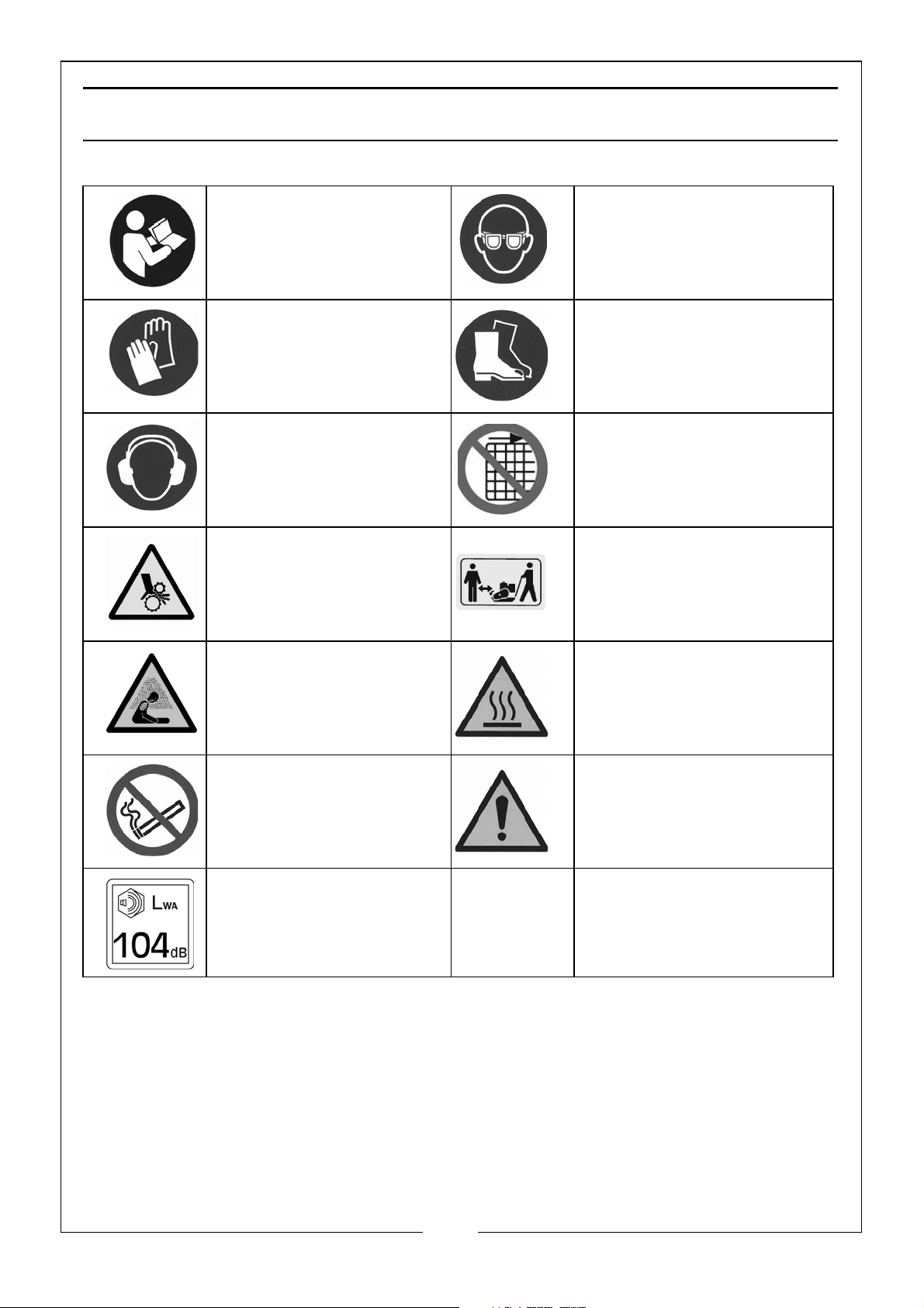
SAFETY SYMBOLS
Read instruction
manuals before use.
Wear anti-vibration
gloves.
Wear ear protection. DO NOT remove or
Warning: Keep away
from rotating parts.
Wear eye protection.
Wear protective
footwear.
tamper with protection
and safety devices.
Keep bystanders at a
safe distance.
Warning: Asphyxiating
Atmosphere. Only use
outdoors or in a well
ventilated area.
Use extreme caution
when handling fuels.
Warning: High Noise
Level
Warning: Hot surfaces
Warning: High Vibration
Risk
5
Parts & Service: 020 8988 7400 / E-mail: [email protected] or [email protected]
Page 6
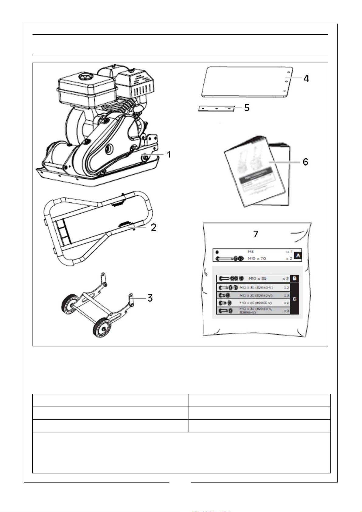
UNPACKING
Remove all components from the packing case and lay them out so that they
can be identified and checked for any possible damage during transit. Should
any component be found to be damaged or missing, please contact your
CLARKE dealer immediately. Check the components against the following list.
1. Compactor Plate Assembly 4. Paving Pad
2. Handle Assembly 5. Clamp Plate
3. Folding Wheel Assembly 6. Engine Manual
7. Hardware Bag:
Handle Assembly (A): M5 Washer x 1, M10 x 70 Bolt, Nut & Washer x 2.
Folding Wheels Assembly (B): M10 x 35 Bolt, Nut & Washers x 2.
Paving Pad Assembly (C): M10 x 30 Bolt, Nut & Washer x 2.
6
Parts & Service: 020 8988 7400 / E-mail: [email protected] or [email protected]
Page 7
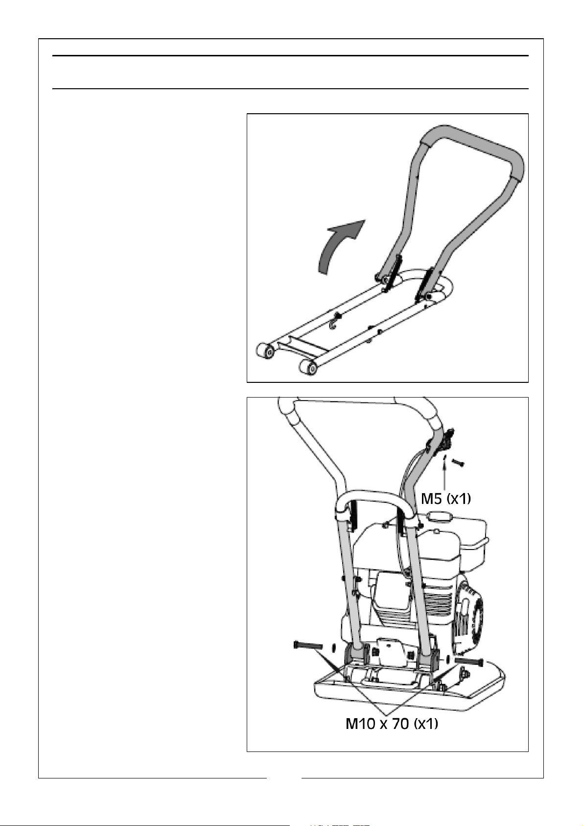
ASSEMBLY
HANDLE ASSEMBLY
(Hardware Bag A)
1. Unfold the handle as
shown.
2. Mount the handle as
shown. Slot the handle
ends into the channels
provided on the engine
deck. Place flat washers
followed by the hex bolts
at the outside and tighten
with lock nuts on the
inside.
3. Unscrew the bolt from the
throttle control. Secure
the throttle control onto
the upper handle with a
flat washer and the bolt
that you have just taken
off the throttle.
4. Fasten the throttle control
cable to the handle using
cable fasteners, making
sure not to hinder the
folding mechanism.
7
Parts & Service: 020 8988 7400 / E-mail: [email protected] or [email protected]
Page 8
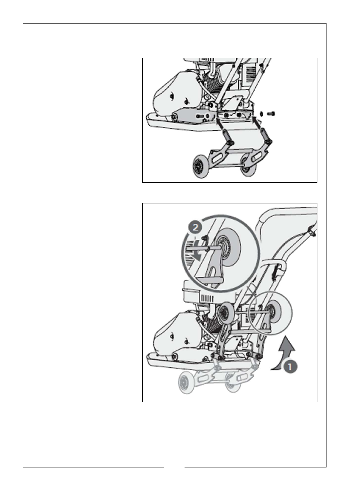
FOLDING WHEELS ASSEMBLY
(Hardware Bag B)
1. Line up the holes in the
link plates and engine
deck, as shown. Slide
the bolts and washers
through the holes from
outside of the machine,
then screw the lock nuts
from the other side and
tighten.
2. Before compacting,
fold up the wheel
assembly (1) and hang
the assembly on the
hooks on the side of the
handle (2), as shown.
8
Parts & Service: 020 8988 7400 / E-mail: [email protected] or [email protected]
Page 9
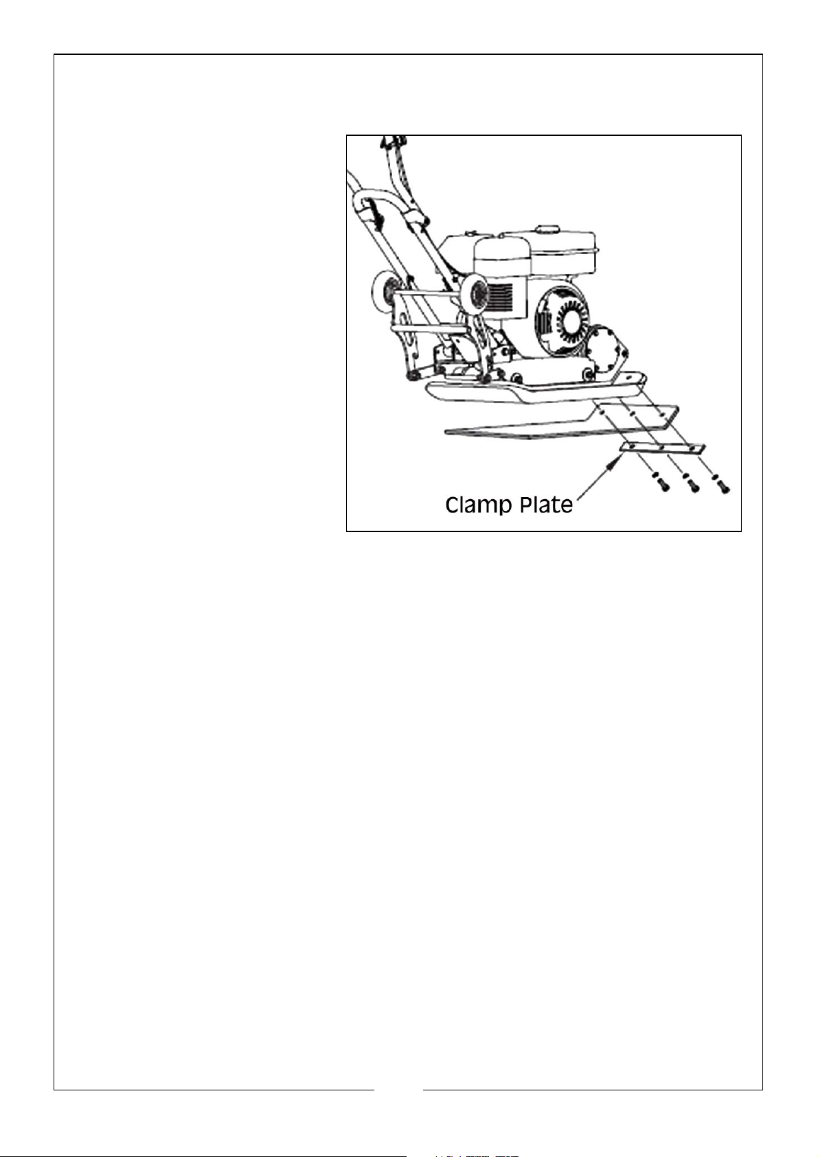
PAVING PAD ASSEMBLY
(Hardware Bag C)
1. Attach the paving pad
onto the base plate as
shown. Align the holes in
the base plate, paving
pad and clamp plate
and secure with bolts,
washers and lock nuts, as
shown.
9
Parts & Service: 020 8988 7400 / E-mail: [email protected] or [email protected]
Page 10
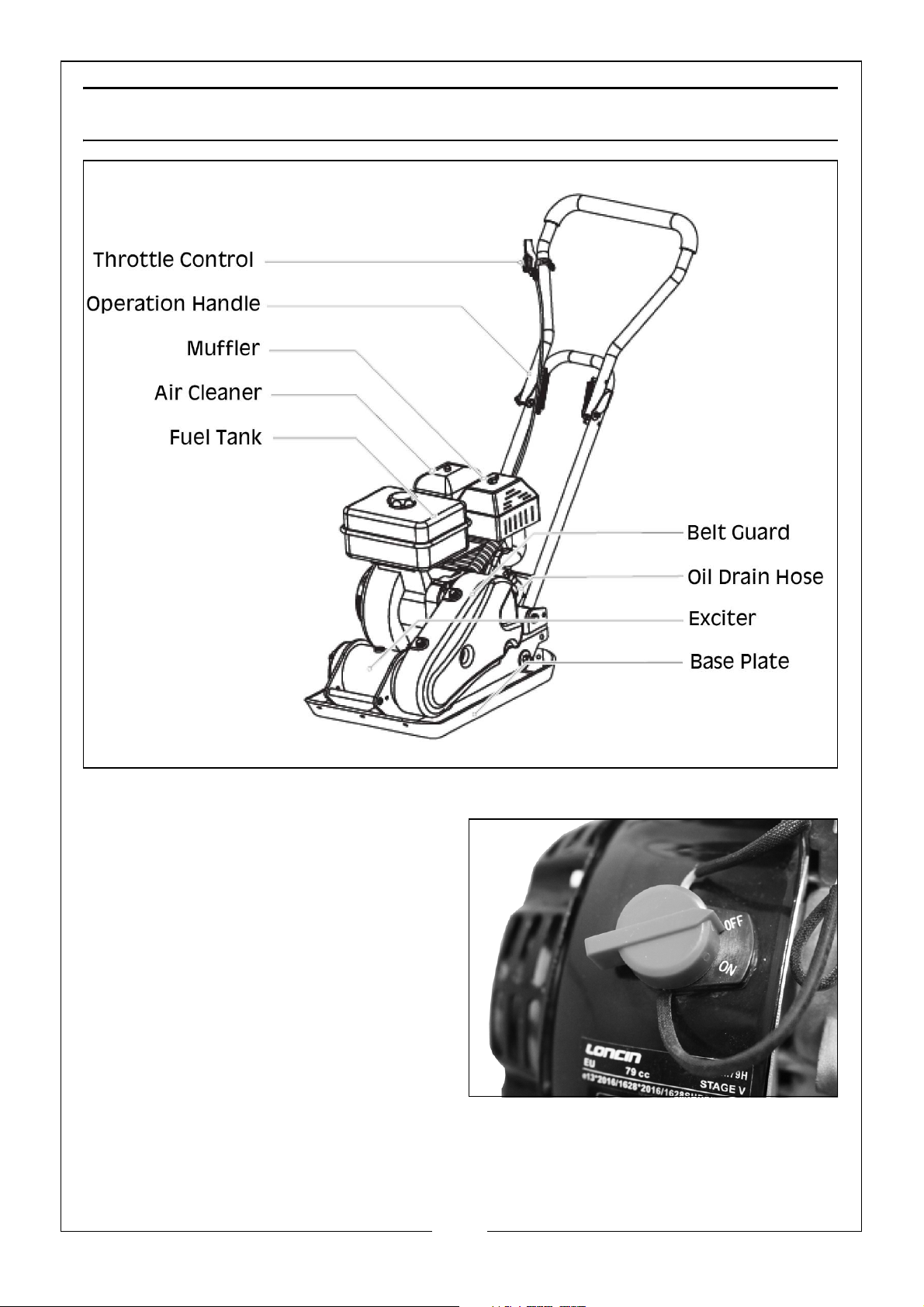
FEATURES AND CONTROLS
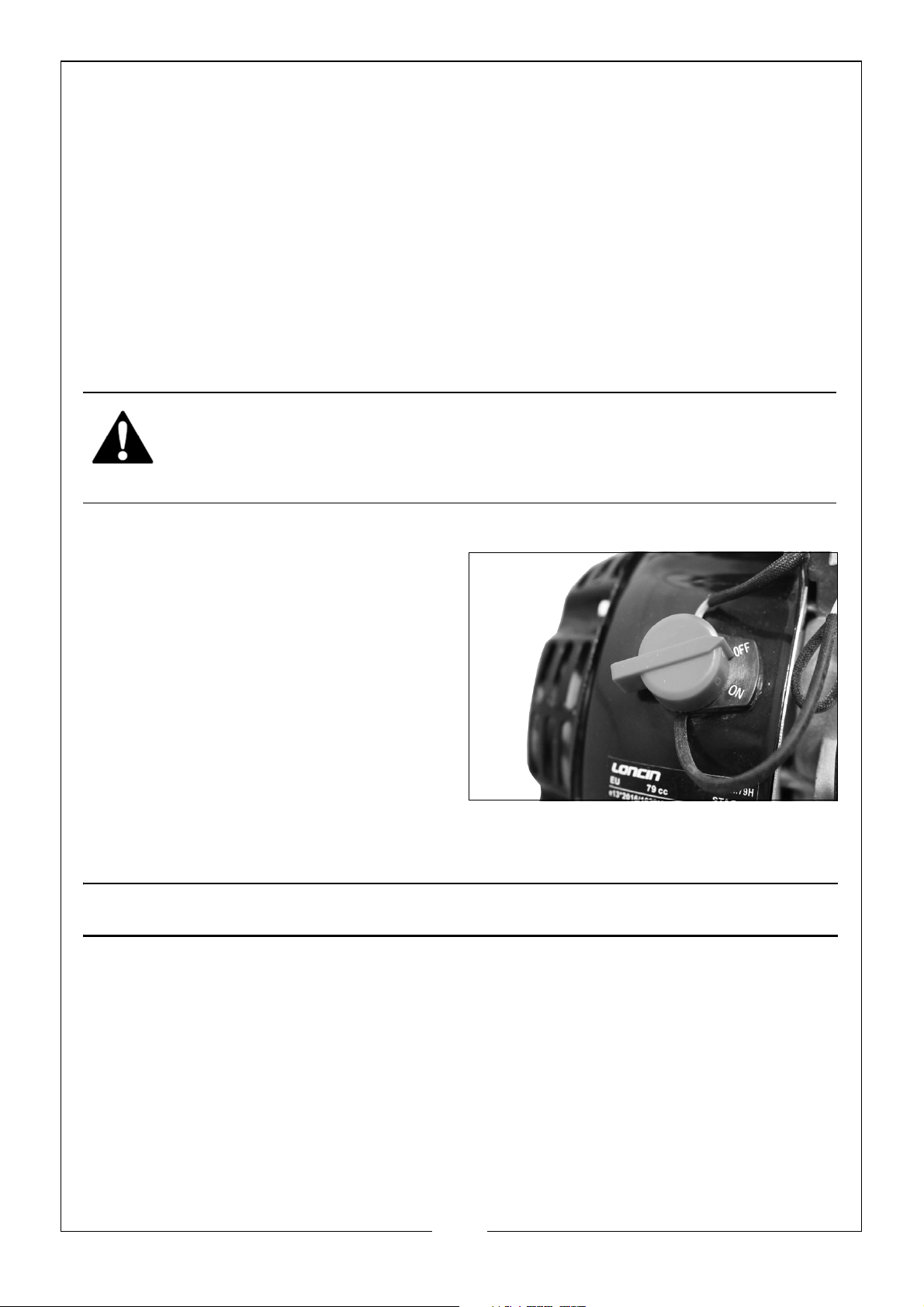
ENGINE SWITCH
The engine switch, located on the
front of the machine, enables and
disables the ignition system. The
engine switch must be in the ON
position for the engine to run. Turning
the engine switch to the OFF position
stops the engine.
10
Parts & Service: 020 8988 7400 / E-mail: [email protected] or [email protected]
Page 11
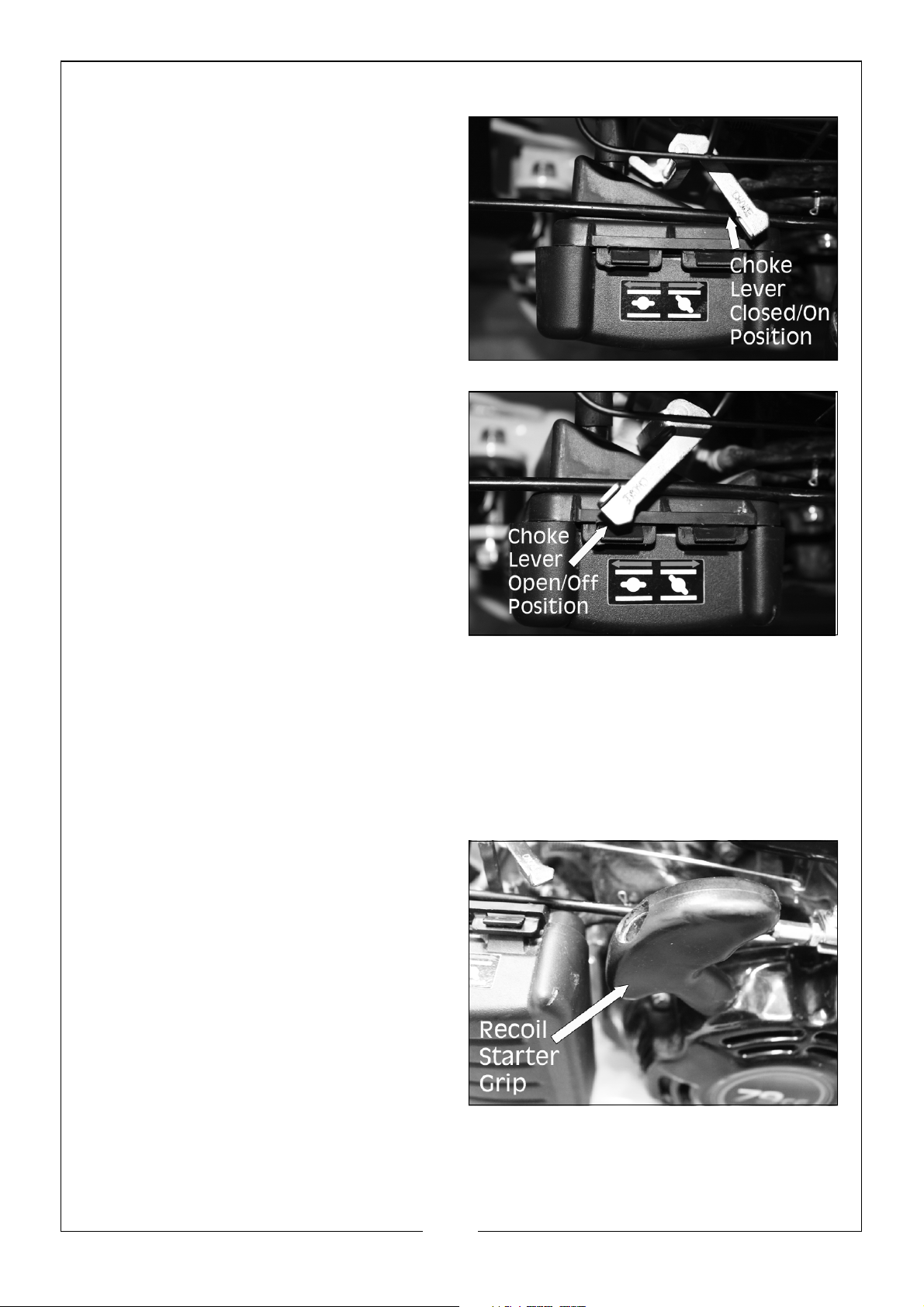
CHOKE LEVER
The choke lever opens and closes the
choke valve in the carburetor. The
CLOSED/ON position enriches the fuel
mixture for starting a cold engine. The
OPEN/OFF position provides the
correct fuel mixture for operation
after starting, and for restarting a
warm engine. Some engine
applications use a remotely mounted
choke control rather than the engine
mounted choke lever.
THROTTLE CONTROL
The throttle lever controls the engine speed. Moving the throttle lever makes
the engine run faster or slower.
RECOIL STARTER GRIP
Pulling the starter grip operates the
recoil starter to crank the engine.
11
Parts & Service: 020 8988 7400 / E-mail: [email protected] or [email protected]
Page 12
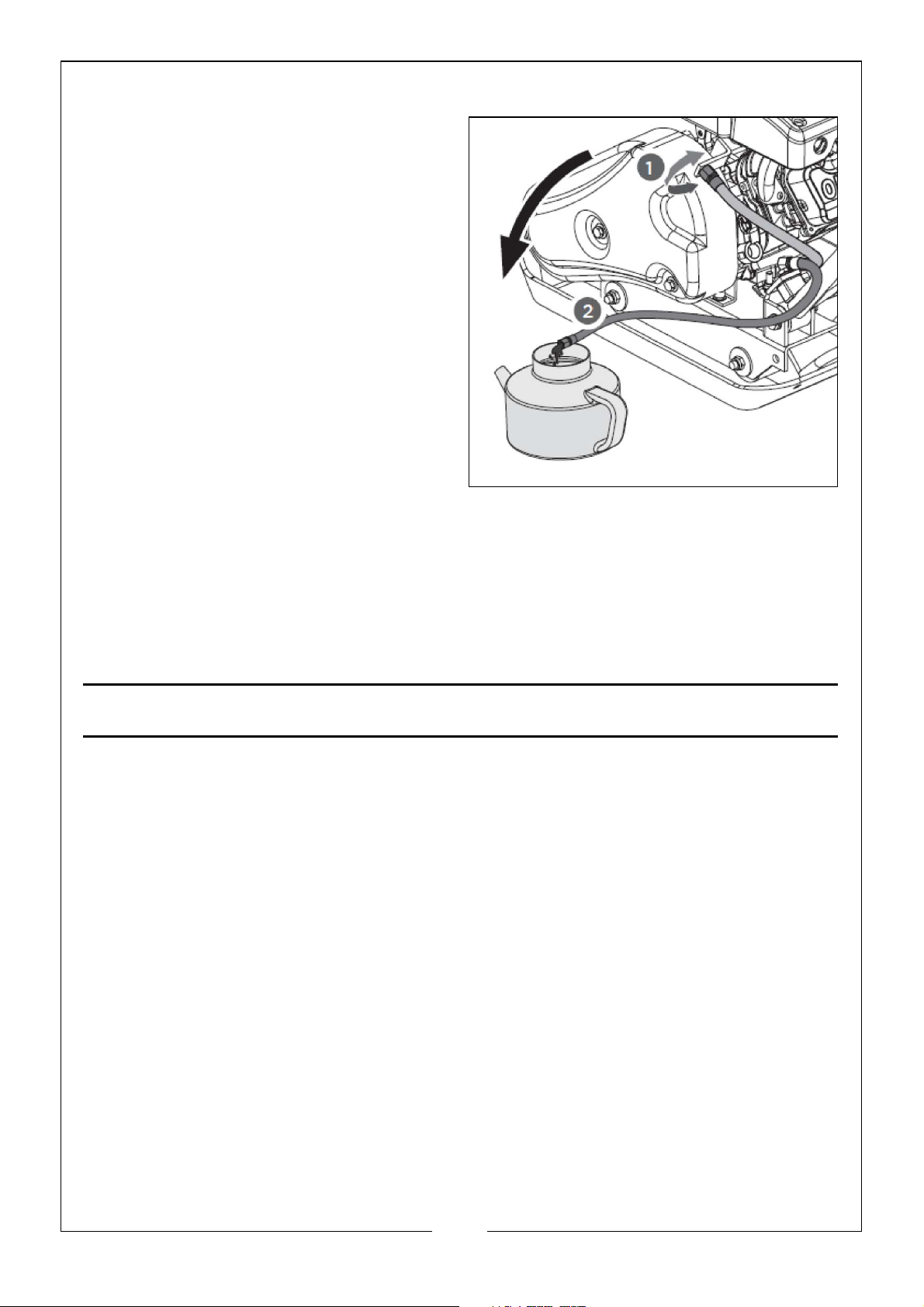
OIL DRAIN HOSE
Running the engine with dirty oil can
cause premature engine wear and
failure. Changing oil regularly is
extremely important. The flexible oil
drain hose is equipped to drain the oil
into an appropriate receptacle.
EXCITER
An eccentric weight mounted on the exciter shaft contained within the
exciter housing is driven at high speed by a clutch and belt drive system. This
high speed shaft revolution causes the rapid lifting and downward ramming
motion of the machine as well as imparting a forward motion.
OPERATION
ADDING ENGINE OIL
NOTE: No engine oil has been supplied within the machine for shipping.
Add oil (Max: 0.35 Litre) according to the Engine Manual.
NOTE: Clarke SAE10W/30 4 Stroke Engine Oil. Part No.: 3050845
ADDING FUEL
Fill the fuel tank (Max: 1.6 Litre) as instructed in the separate engine manual
packed with this machine, using E10 Petrol.
NOTE: More detailed description of the engine operation and all related
precautions and procedures can be found in the engine manual.
STARTING THE ENGINE
1. To start
• A COLD ENGINE: Move the choke lever to the CLOSED position.
12
Parts & Service: 020 8988 7400 / E-mail: [email protected] or [email protected]
Page 13

• A WARM ENGINE: Move the choke lever to the OPEN position.
2. Move the throttle lever away from the SLOW position, about 1/3 of the way
towards the FAST position.
3. Turn the engine switch, located on the front of the machine, to the ON
position.
4. Pull the Recoil Starter Grip to start the machine.
OPERATING
WARNING: DO NOT operate the plate on concrete or extremely hard,
dry, compacted surfaces. The plate will jump rather than vibrate and
could damage the plate, engine and/or the surface.
1. After the engine has warmed up, pull the throttle lever to accelerate the
engine speed. The plate will begin to vibrate and move forward.
2. The plate compactor is designed to run at an engine speed (engine take
off shaft) of 3600 rpm (normally considered full throttle). Running the engine
at lower rpm will result in a decrease of compaction force and lower travel
speed. It will create excessive ‘out of sync’ vibrations resulting in poor
compaction, maneuverability, excessive wear to the machine, and
discomfort to the operator.
3. In operation, guide the machine but let the compactor do the work.
Bearing down on the handle is unnecessary and causes the shock
absorber to wear.
4. On level surfaces the compactor will move forward rapidly. On uneven
surfaces or inclines, light forward pressure on the handle may be required
to assist the compactor in moving forward.
5. The number of passes required to reach a desired compaction level will
depend on the type and moisture content of the soil. Maximum soil
compaction has been reached when excessive kickback is noticed.
NOTE: When using a compactor on newly laid asphalt, a water sprinkler
kit is required to help prevent the bottom plate from adhering to
the hot asphalt surface.
NOTE: When using the plate on paving stones, attach the pad to the
bottom of the plate to prevent chipping or grinding the surface of
the stones.
NOTE: While a certain amount of moisture in the soil is necessary,
excessive moisture may cause soil particles to stick together and
prevent good compaction. If the soil is extremely wet, allow it to
dry somewhat before compacting.
13
Parts & Service: 020 8988 7400 / E-mail: [email protected] or [email protected]
Page 14
NOTE: If the soil is too dry as to create dust clouds while operating the
plate, some moisture should be added to the ground material to
improve compacting. This will also reduce the air filter from
clogging.
IDLE SPEED
Set the throttle control lever to its LOW position to reduce stress on the engine
when compacting is not being performed. Lowering the engine speed to idle
will help extend the life of the engine, as well as conserve fuel and reduce the
noise level of the machine.
STOPPING THE ENGINE
WARNING: DO NOT MOVE THE CHOKE LEVER TO THE CLOSE POSITION TO
STOP THE ENGINE. BACKFIRE OR ENGINE DAMAGE MAY OCCUR.
WARNING:
To stop the engine in an emergency,
simply turn the engine switch to the
OFF position. Under normal
conditions, use the following
procedure:
1. Move the throttle lever to the
SLOW position.
2. Let the engine idle for one or two
minutes.
3. Turn the engine switch to the OFF
position.
CARE AND MAINTENANCE
Maintaining your compactor will ensure long life of the machine components.
PREVENTATIVE MAINTENANCE
1. Turn off the engine. Engine must be cool before any maintenance takes
place.
2. Keep the engine’s throttle lever in the SLOW position, and remove the
spark plug wire from the spark plug and secure.
14
Parts & Service: 020 8988 7400 / E-mail: [email protected] or [email protected]
Page 15
3. Inspect the general condition of the plate compactor. Check for loose
screws, misalignment or binding of moving parts, cracked or broken parts,
and any other condition that may affect its safe operation.
4. Remove all debris from the plate compactor with a soft brush, vacuum or
compressed air (Always use safety glasses when using compressed air).
Then use a premium quality lightweight machine oil to lubricate all moving
parts.
5. Clean the bottom of the compactor base plate as soon as it begins to pick
up soil being compacted. The unit can not do a good job if the bottom
surface is not smooth and clean.
6. Replace the spark plug wire
WARNING: NEVER USE A PRESSURE WASHER TO CLEAN THE COMPACTOR
PLATE. WATER CAN PENETRATE TIGHT AREAS OF THE UNIT AND CAUSE
DAMAGE TO SPINDLES, PULLEYS AND BEARINGS OF THE ENGINE. THE USE
OF A PRESSURE WASHER WILL RESULT IN SHORTENING THE LIFE OF THE UNIT
AND REDUCE SERVICEABILITY.
CHECKING THE V-BELT
To ensure optimum power transmission from the engine to the eccentric shaft,
the V-Belt must be in good condition and operate under proper tension.
1. Turn off the engine. The engine must be cool before proceeding.
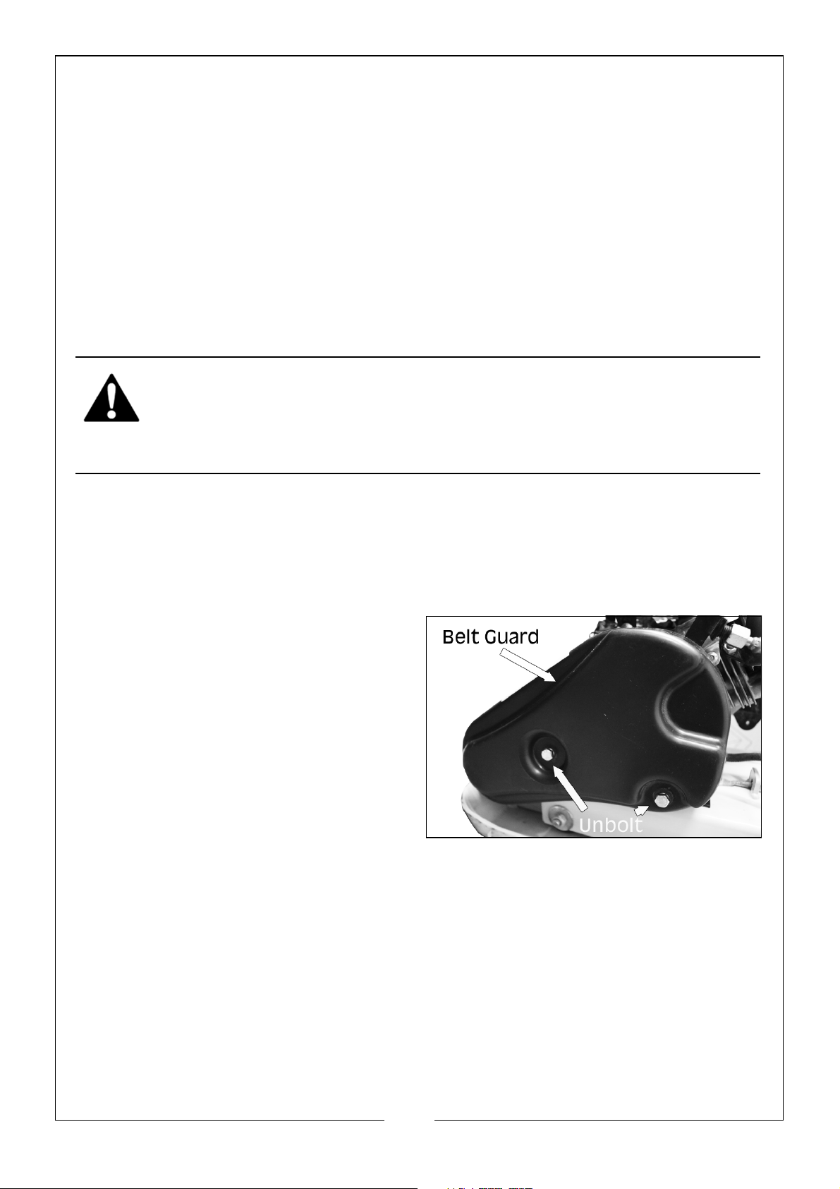
2. Remove the belt guard to access
the V-Belt.
3. Check the condition of the V-Belt.
If any of the V-Belt is cracked,
frayed or grazed, it should be
replaced as soon as convenient.
4. Check the V-Belt tension by
squeezing the two sides together
in the centre. The normal
deflection on each side should be
9mm (3/8”) to 13mm (1/2”) with moderate pressure from your thumb and
finger.
NOTE: On new machines or after installing a new belt, check the belt
tension after the first 20 hours of operation. Check and adjust the
belt every 50 hours thereafter.
TENSIONING THE V-BELT
Proper belt tension is critical to good performance. Proper adjustment will
assure long belt life. Too much or too little belt tension will cause premature
belt failure.
15
Parts & Service: 020 8988 7400 / E-mail: [email protected] or [email protected]
Page 16
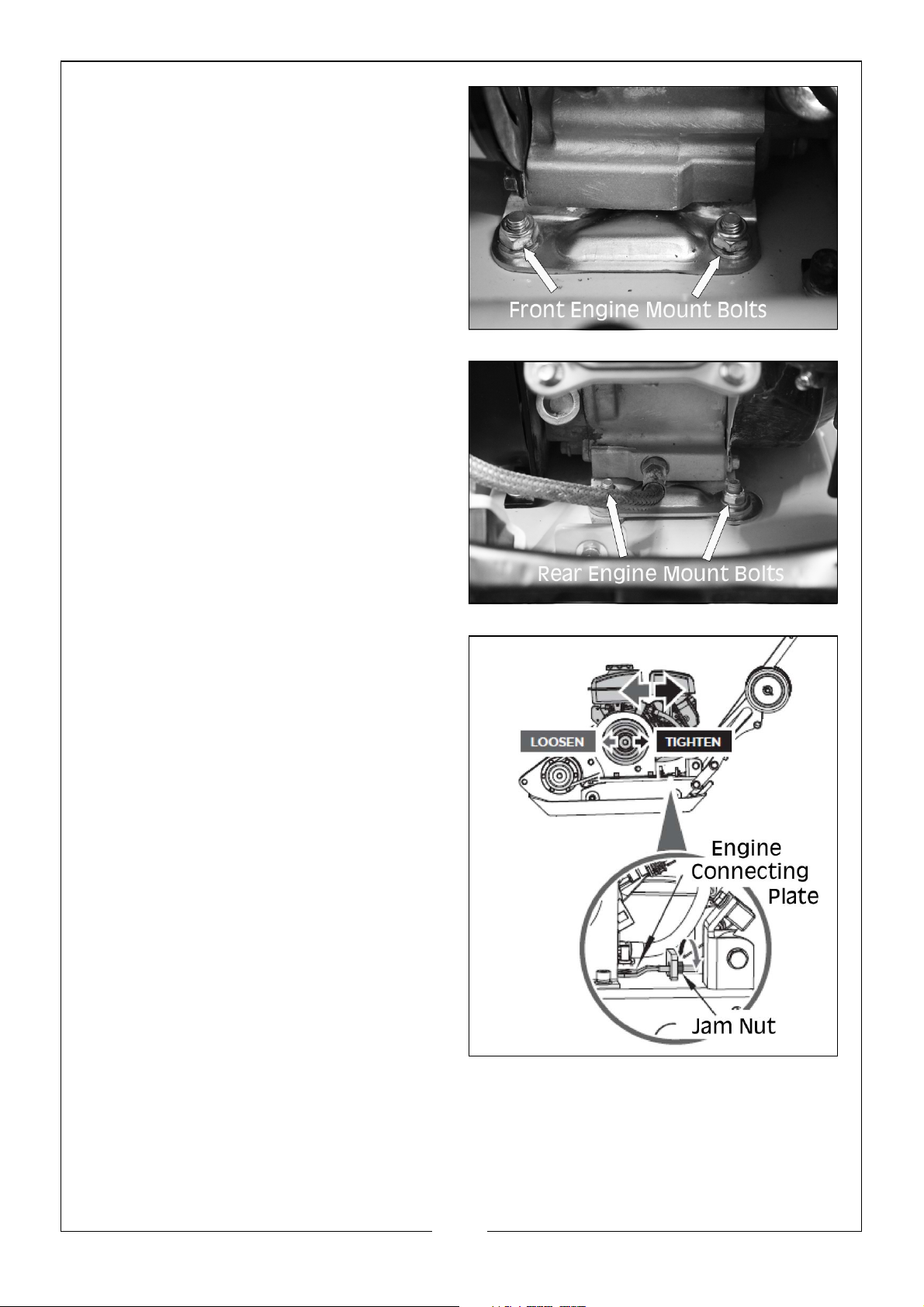
1. Loosen the 4 engine mount bolts
(DO NOT remove), only enough to
move the engine forward.
2. Loosen the jam nut as shown,
leaving enough space between
the nut and bracket.
3. Push the engine towards the back
of the plate by turning the
adjustment bolts to remove any
slack in the V-Belt.
NOTE: If the adjustment bolts have
no more adjustment left, the
belt may have to be
replaced.
16
Parts & Service: 020 8988 7400 / E-mail: [email protected] or [email protected]
Page 17
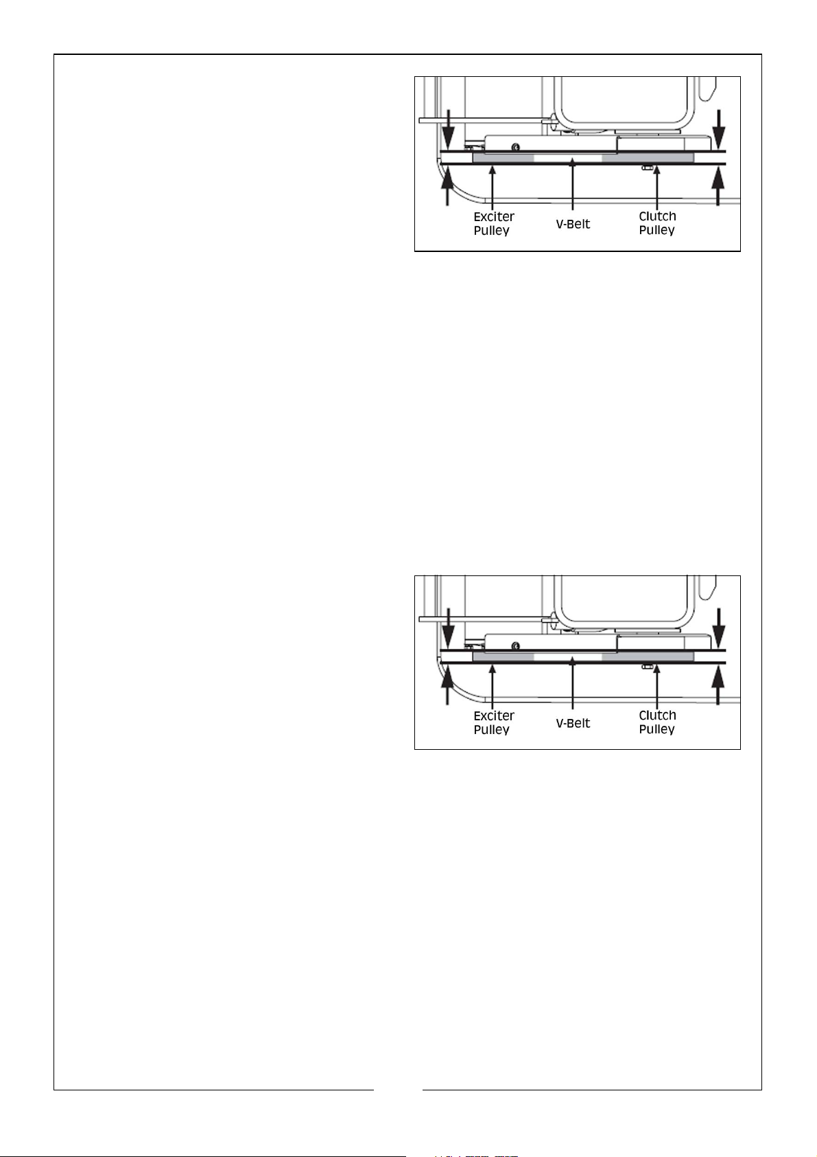
4. When adjusting the belt, make
sure the clutch pulley is in
alignment with the exciter pulley,
as shown.
5. When the V-Belt tension is correct,
tighten the jam nut against the
bracket.
6. Tighten the engine mount bolts.
7. Replace the belt guard.
REPLACING THE V-BELT
1. Loosen the 4 engine mount bolts (DO NOT remove), only enough to move
the engine forward.
2. Loosen the jam nut as shown above, leaving enough space between the
nut and bracket.
3. Slide the engine toward the front of the plate and slip the old V-Belt off the
pulleys and install the new V-Belt in its place.
4. Move the engine back.
5. When the the V-Belt tension is
correct and the pulleys are
aligned, tighten the jam nut and
the engine mount bolts.
6. Replace the belt guard.
EXCITER LUBRICATION
The exciter housing is pre-serviced using Automatic Transmission Fluid e.g.
DEXTRON III, MERCON, EXXON NUTO H-32 or equivalent. Change the fluid after
200 hours of operation.
17
Parts & Service: 020 8988 7400 / E-mail: [email protected] or [email protected]
Page 18
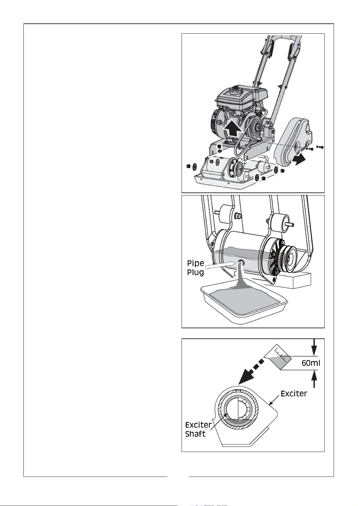
1. Turn off the engine and let the
exciter cool before changing the
exciter oil.
2. Remove the belt guard and VBelt.
3. Remove the bolts that hold the
deck to the housing.
4. Lift entire deck with engine from
the housing, as shown.
5. Remove the pipe plug from the
top of the exciter housing. Tilt the
housing upside down so the oil
can drain from the exciter.
Examine the oil for metal chips as
a precaution of future problems.
6. Return the plate housing to the
upright position.
7. Fill the exciter housing with 60ml of
transmission fluid oil.
8. Apply pipe sealant to the pipe
plug and reinstall into the top of
the exciter housing.
9. Reinstall the deck, V-Belt and belt
guard.
18
Parts & Service: 020 8988 7400 / E-mail: [email protected] or [email protected]
Page 19
ENGINE MAINTENANCE
Refer to the engine manual that is included with the compactor plate for the
relevant information on engine maintenance. Your engine manual provides
detailed information for performing this task.
STORAGE & TRANSPORTING
STORAGE
If the compactor plate will not be used for a period longer than 30 days, follow
the steps below to prepare the unit for storage.
1. Drain the fuel tank completely. Stored fuel containing ethanol or MTBE can
start to go stale in 30 days. Stale fuel has a high gum content and can clog
the carburetor and restrict fuel flow.
2. Start the engine and allow it to run until it stops. This ensures no fuel is left in
the carburetor. This will also help prevent deposits from forming inside the
carburetor and possible engine damage.
3. While the engine is still warm, drain the oil from the engine. refill with fresh oil
of the grade recommended in the engine manual.
4. Allow the engine to cool. Remove the spark plug and put 60ml of SAE-30 oil
into the cylinder. Pull the starter rope slowly to distribute the oil. Replace the
spark plug.
NOTE: Remove the spark plug and drain all of the oil from the cylinder
before attempting to start the unit after storage.
5. Use a clean cloth to clean off the outside of the compactor and keep the
air vents free of obstructions.
NOTE: DO NOT use strong detergents or petroleum based cleaners when
cleaning plastic parts. Chemicals can damage plastics.
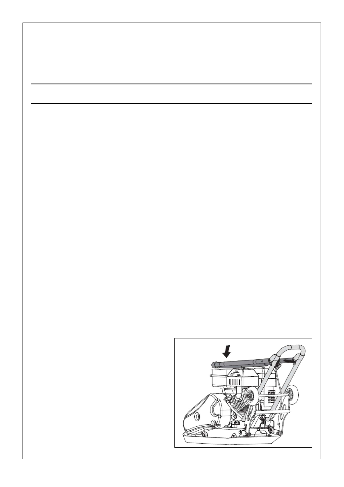
6. Pull up the spring bolt and fold up
the wheel bracket.
7. Carefully fold the upper handle
down. DO NOT allow the control
cable to become pinched or
bent.
8. Store the plate compactor in an
upright position in a clean, dry
space that has good ventilation.
19
Parts & Service: 020 8988 7400 / E-mail: [email protected] or [email protected]
Page 20
LIFTING & TRANSPORTATION
NOTE: To avoid burns or fire hazard, let engine cool before lifting,
transporting and storing the unit.
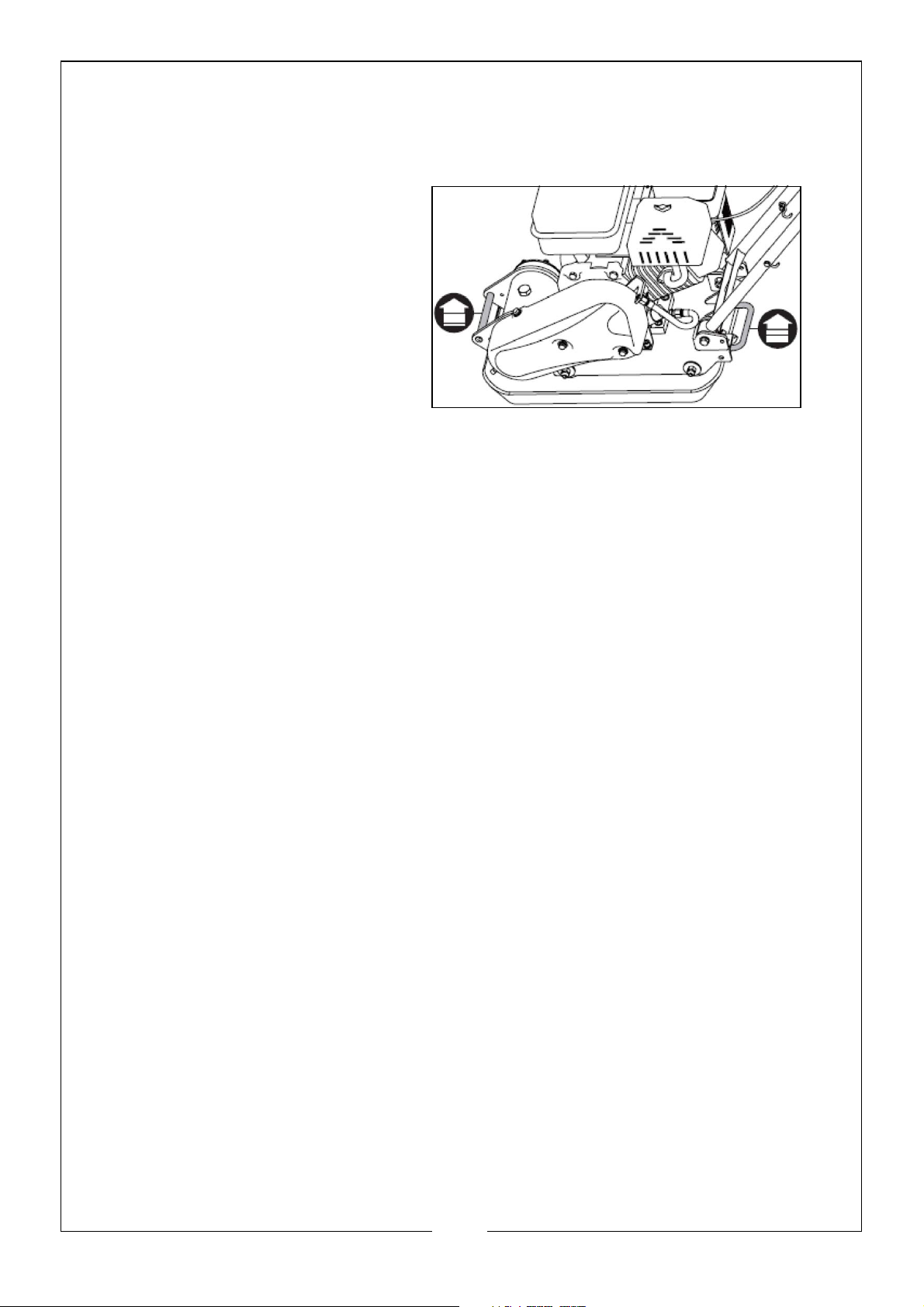
NOTE: This unit weights 50kg, it is
recommended that 2
persons lift the machine,
via the lift handles, as
shown.
NOTE: The unit must be
transported in the
upright position to
prevent fuel from spilling.
DO NOT lay the machine
on its side or top.
NOTE: When transporting, secure or tie down the unit using the lift
handles to prevent it from sliding or tipping over.
20
Parts & Service: 020 8988 7400 / E-mail: [email protected] or [email protected]
Page 21
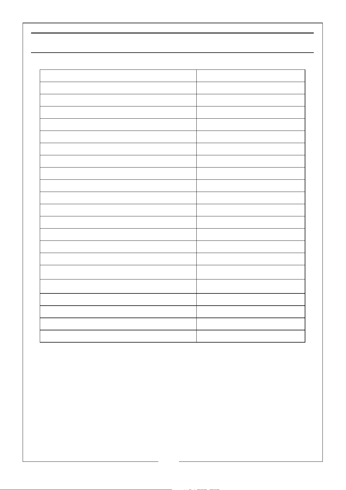
SPECIFICATION
Model No CPCP1
Plate Size (L x W x D) 495mm x 320mm x 6mm
Centrifugal Force 8200 N
Exciter Speed 5900VPM
Compaction Depth 200mm
Travel Speed 25m/min
Engine Power 2HP, 1.5Kw
Engine Displacement 79cc
Fuel Tank Capacity (E10 Petrol) 1.6 Litre
Fuel Consumption 0.68 L/H
Run Time @ 75% Rated Load 2.3 Hours
Engine Oil Capacity (SAE10W/30) 0.35 Litre
Dimensions (Folded): (D x W x H) 890mm x 315mm x 570mm
Dimensions (Unfolded): (D x W x H) 1110mm x 315mm x 820mm
Weight (without fuel & oil) 50 kg
IP Rating IP44D
Vibration
Uncertainty Factor K
17.5 m/s
3 m/s
2
2
Sound Pressure level 99.4 dB Lpa
Sound Power Level 99.4 dB LwA
Guaranteed Sound Power Level 104 dB LwA*
Uncertainty Factor K 3 dB
* = Caution: Registered guaranteed sound power level is just for the engine.
Sound power levels maybe higher depending on the surface the machine is
working on.
21
Parts & Service: 020 8988 7400 / E-mail: [email protected] or [email protected]
Page 22
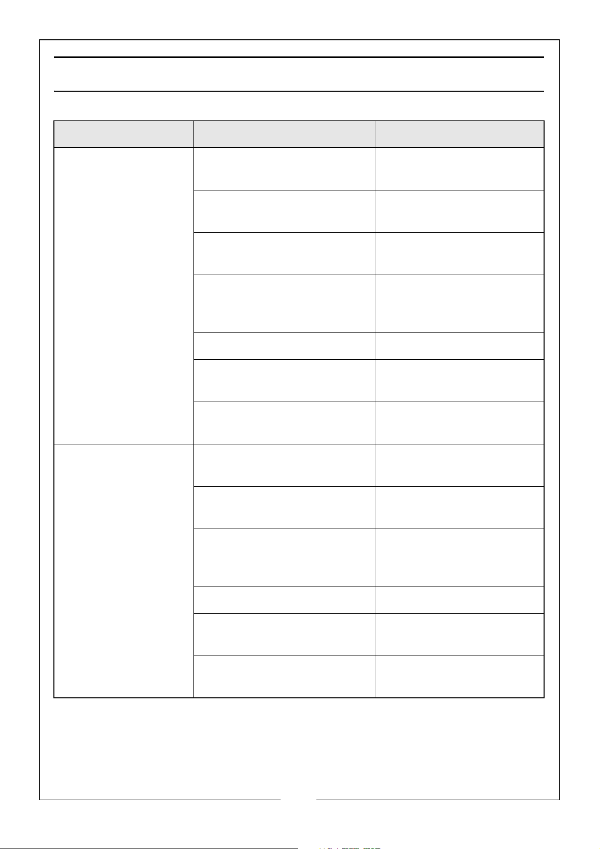
TROUBLESHOOTING
PROBLEM POSSIBLE CAUSE SOLUTION
Engine fails to start 1. Spark plug wire is
disconnected
2. Out of fuel or fuel is stale 2. Fill with clean fresh
3. Throttle control lever not
in correct starting position
4. Choke not in ON position 4. Throttle must be
5. Blocked fuel line 5. Clean the fuel line
6. Fouled spark plug 6. Clean, adjust gap or
7. Engine carburettor
flooding
1. Attach spark plug wire
securely to the spark plug
petrol
3. Move throttle control
lever to the START position
positioned at choke for a
cold start
replace
7. Wait a few minutes to
restart, but DO NOT prime
Engine runs
erratically
1. Spark plug wire loose 1. Connect and tighten
the spark plug wire
2. Unit running on CHOKE 2. Move choke lever to
the OFF position
3. Blocked fuel line or stale
fuel
4. Vent plugged 4. Clear vent
5. Water or dirt in fuel system 5. Drain fuel tank. Refill
6.Dirty air cleaner 6. Clean or replace air
3. Clean the fuel line. Fill
tank with clean fresh
petrol
with fresh petrol
cleaner
22
Parts & Service: 020 8988 7400 / E-mail: [email protected] or [email protected]
Page 23

PROBLEM POSSIBLE CAUSE SOLUTION
Engine
overheats
Engine will not stop
when
throttle control is
positioned at stop, or
engine speed does
not increase
properly when
throttle control is
adjusted
Compactor is difficult
to
control when
pounding (machine
lumps or lurches
forward)
1. Engine oil level low 1.Fill crankcase with
proper oil
2. Dirty air cleaner 2.Clean air cleaner
3. Air flow restricted 3.Remove blower
housing and clean
1. Debris interfering with
throttle linkage
1. Too high engine speed on
hard ground
1. Clean dirt and debris
away
1. Set the throttle lever at
lower speed
23
Parts & Service: 020 8988 7400 / E-mail: [email protected] or [email protected]
Page 24
Page 25
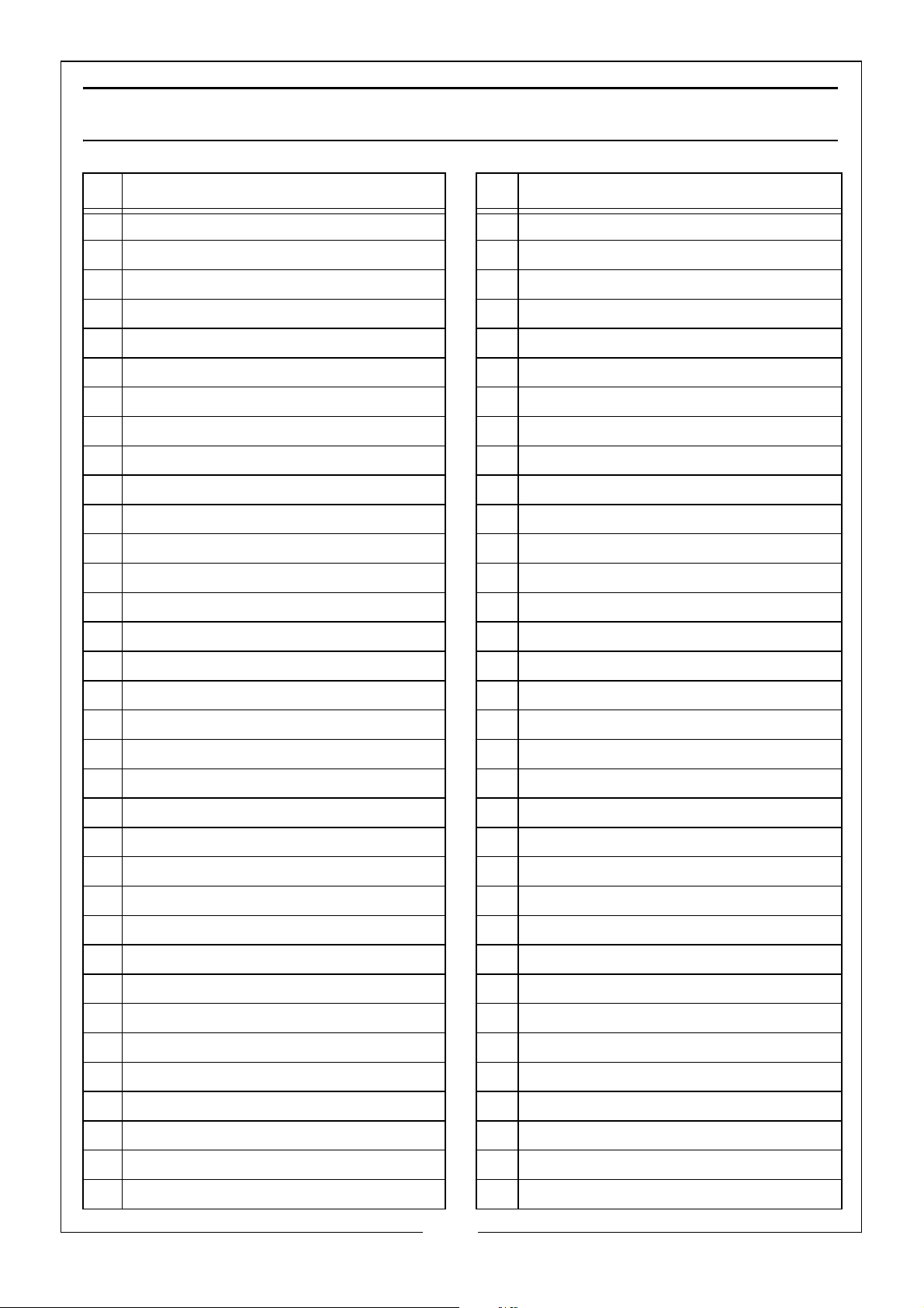
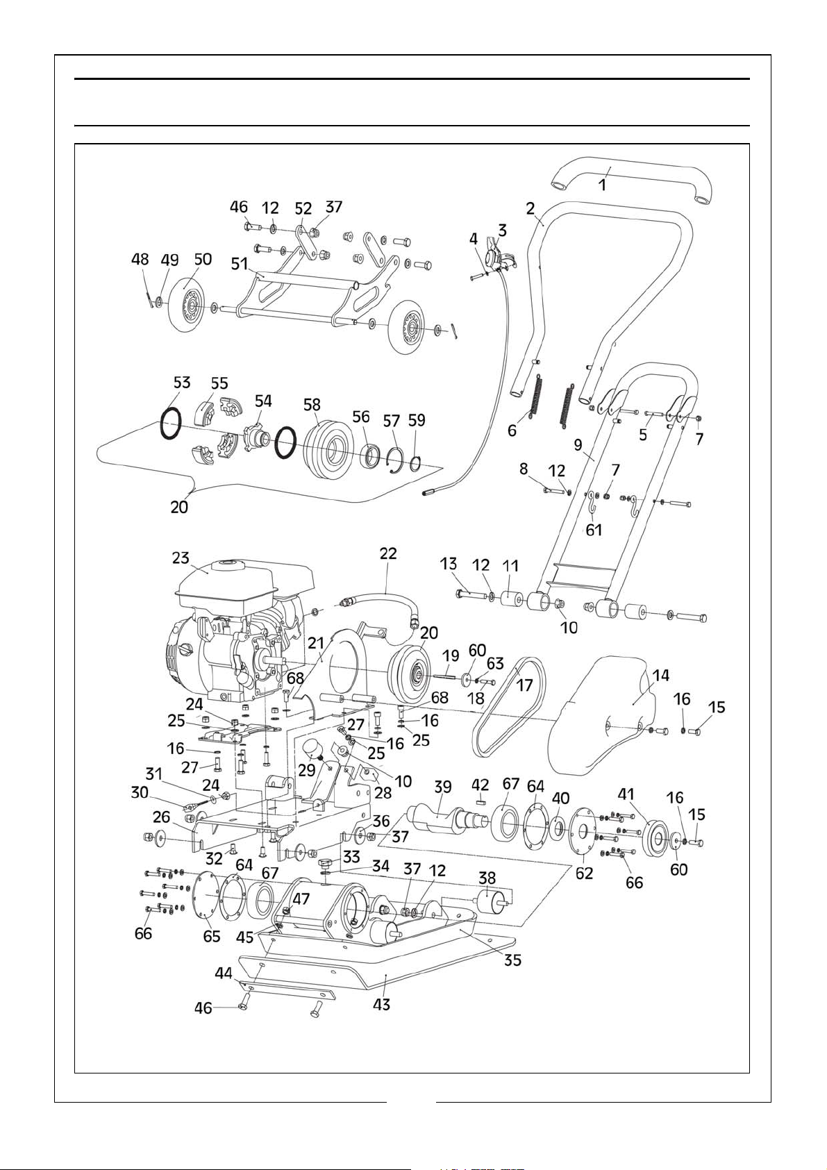
COMPONENT PARTS LIST
ID DESCRIPTION ID DESCRIPTION
1 Handle Sleeve 35 Base Plate
2 Upper Handle 36 Flat Washer 10
3 Throttle Control 37 Locknut M10
4 Flat Washer 5 38 Shock Absorbing Support
5 Bolt M6 x 50 39 Eccentric Shaft
6 Spring 40 Sealing Ring
7 Locknut M6 41 Pulley
8 Bolt M6 x 40 42 Flat Washer B6 x 18
9 Lower Handle 43 Rubber Pad
10 Locknut M10 44 Clamp Plate
11 Rubber Sleeve 45 Spring Washer 10
12 Flat Washer 10 46 Bolt M10 x 30
13 Bolt M10 x 65 47 Nut
14 Belt Cover 48 Cotter Pin 2.5 x 25
15 Bolt M8 x 20 49 Flat Washer 12
16 Spring Washer 8 50 Wheel
17 V Belt A660 51 Bracket
18 Bolt M6 x 25 52 Connecting Plate
19 Flat Key 5 x 5 x35 53 Clutch Spring
20 Clutch Pulley 54 Clutch Shaft
21 Belt Cover Mounting Plate 55 Clutch Lining
22 Oil Hose Assembly 56 Bearing 6006-2RS
23 Engine 57 Circlip 55
24 Locknut M8 58 Clutch Pulley
25 Flat Washer 8 59 Circlip 30
26 Engine Mounting Bracket 60 Pressing Plate
27 Bolt M8 x 16 61 Hook
28 Handle Limit - Upper 62 Bearing End Cap - Left
29 Shock Absorbing Support 63 Spring Washer 6
30 Pull Bolt 64 Gasket
31 Large Washer 6 65 Bearing End Cap - Right
32 Bolts M8 x 20, M8 x 25 66 Bolt M6 x 20
33 Air Plug Screw 67 Bearing 6307
34 Sealing Washers 68 Screw M8 x 14
25
Parts & Service: 020 8988 7400 / E-mail: [email protected] or [email protected]
Page 26
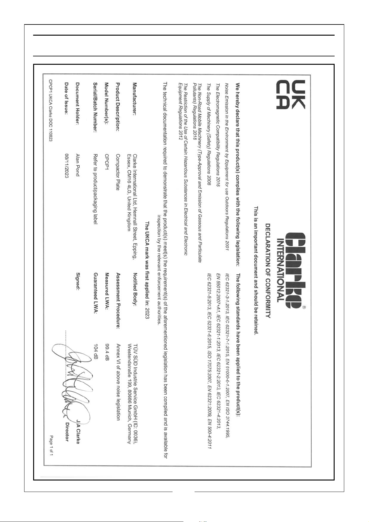
DECLARATIONS OF CONFORMITY-UK
26
Parts & Service: 020 8988 7400 / E-mail: [email protected] or [email protected]
Page 27
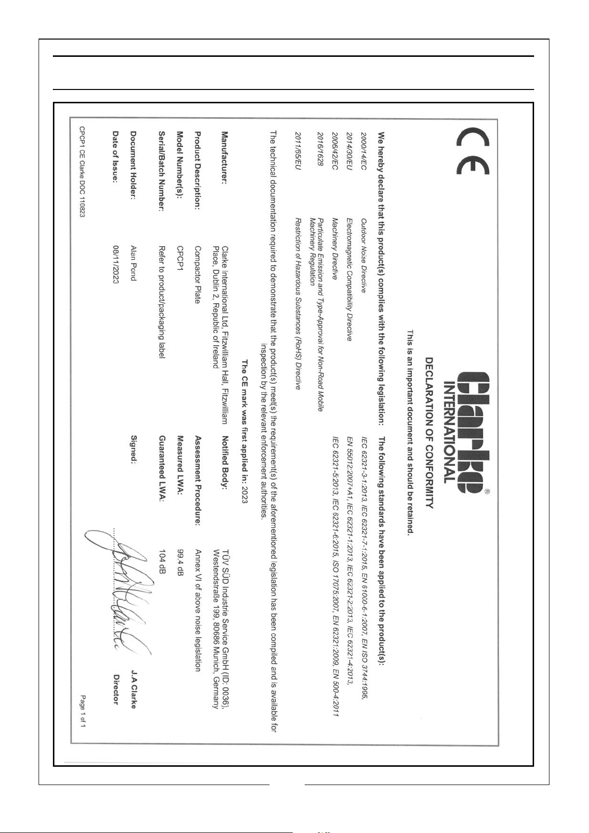
DECLARATIONS OF CONFORMITY-EU
27
Parts & Service: 020 8988 7400 / E-mail: [email protected] or [email protected]
Page 28

 Loading...