

Page 1
OPERATING & MAINTENANCE
INSTRUCTIONS
GC0309
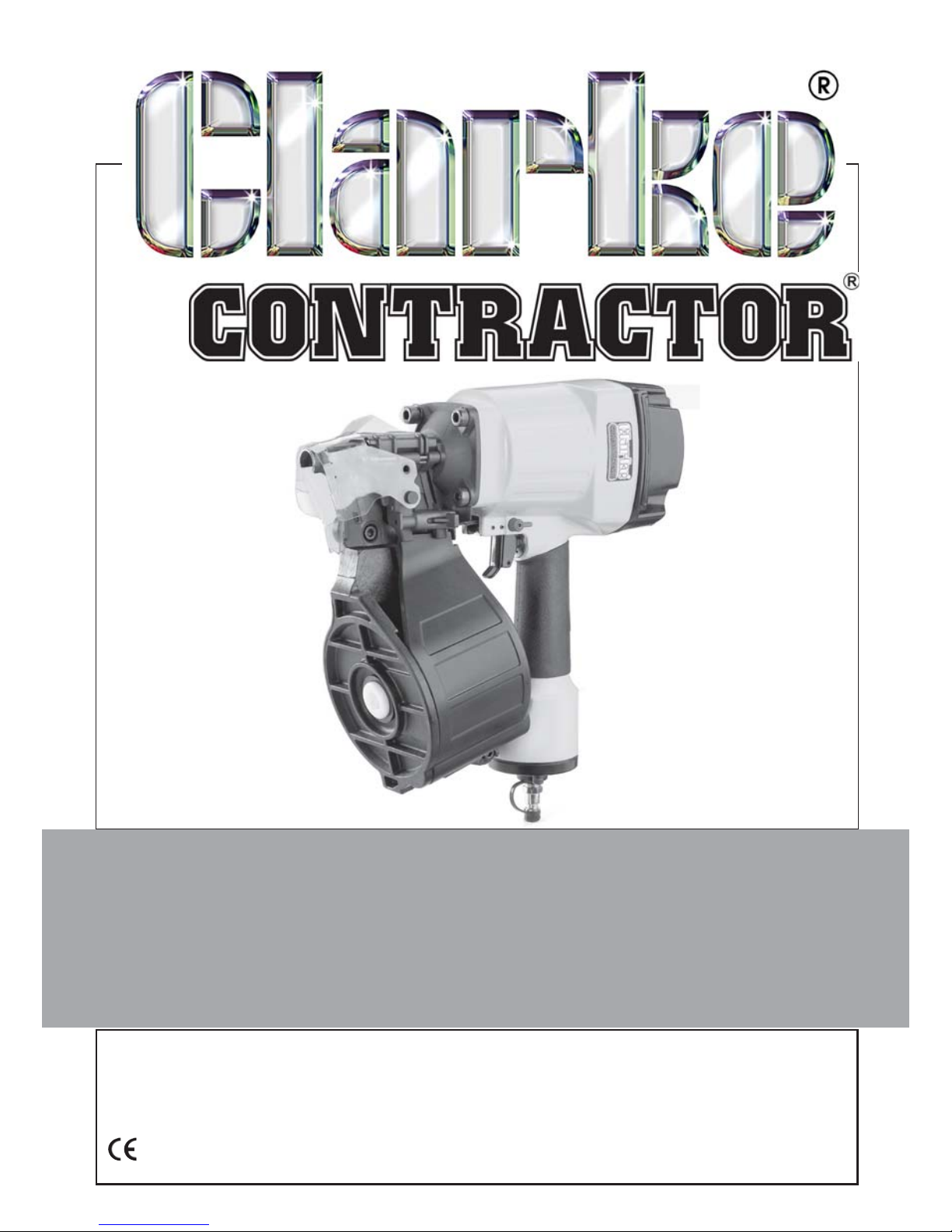
15 DEGREE COIL NAILER
Model CON15
Part No: 3110295
Page 2
2
INTRODUCTION
Thank you for purchasing this CLARKE Coil Nailer
Before attempting to operate the machine, it is essential that you read this
manual thoroughly and carefully follow all instructions given. In doing so you
will ensure the safety of yourself and that of others around you, and you can
also look forward to the product giving you long and satisfactory service.
GUARANTEE
This CLARKE product is guaranteed against faulty manufacture for a period of
12 months from the date of purchase. Please keep your receipt as proof of
purchase.
This guarantee is invalid if the product is found to have been abused or
tampered with in any way, or not used for the purpose for which it was
intended.
Faulty goods should be returned to their place of purchase, no product can
be returned to us without prior permission.
This guarantee does not effect your statutory rights.
ENVIRONMENTAL PROTECTION
Do not dispose of this product with general household waste. All tools,
accessories and packaging should be sorted, taken to a recycling
centre and disposed of appropriately.
PARTS & SERVICE
For parts & Servicing, please contact your nearest dealer, or
CLARKE International, on one of the following numbers.
PARTS & SERVICE TEL: 020 8988 7400
PARTS & SERVICE FAX: 020 8558 3622
or e-mail as follows:
PARTS: [email protected]
SERVICE: [email protected]
Page 3
3
OVERVIEW
The CON15 Coil Nailer is suitable for use on softwood, hardwood, plywood,
hardboard, fibreboard or MDF, and will penetrate flexible plastics, leather,
fabrics, PVC & rubber sheet materials. It is not suitable for piercing hard
laminates, brittle plastics or metals (other than light foil).
Unpack and lay out the components, checking against the following list. Any
damage or deficiency should be reported to your Clarke dealer immediately.
• Coil Nailer
• Oil Bottle
• 4 x Hexagonal Keys (3 ,4, 5 & 6mm)
• 1 x Nail Roll
• Black Moulded Case
• Operators Manual (this document)
Your Coil Nailer has been designed to give long and trouble free service. If,
however, having followed the instructions in this booklet carefully, you
encounter problems, take the unit to your local Clarke dealer.
TECHNICAL SPECIFICATION
erutaeF noitacificepS
thgieWgk4
mm)hxwxl(snoisnemiD553x031x033
erusserPriAgnitarepO)rab9.6-8.4(isp001-07
erusserPriA
xaM)rab2.8(isp021
deepSevirDnim/slian003
noitpmusnoCriAdesserpmoCmfc5.6
noitcennoCenilriAelamPSB"4/1
yticapaC
enizagaMslian003
Please note that the details and specifications contained herein, are correct at the
time of going to print. However, CLARKE International reserve the right to change
specifications at any time without prior notice.
Page 4
4
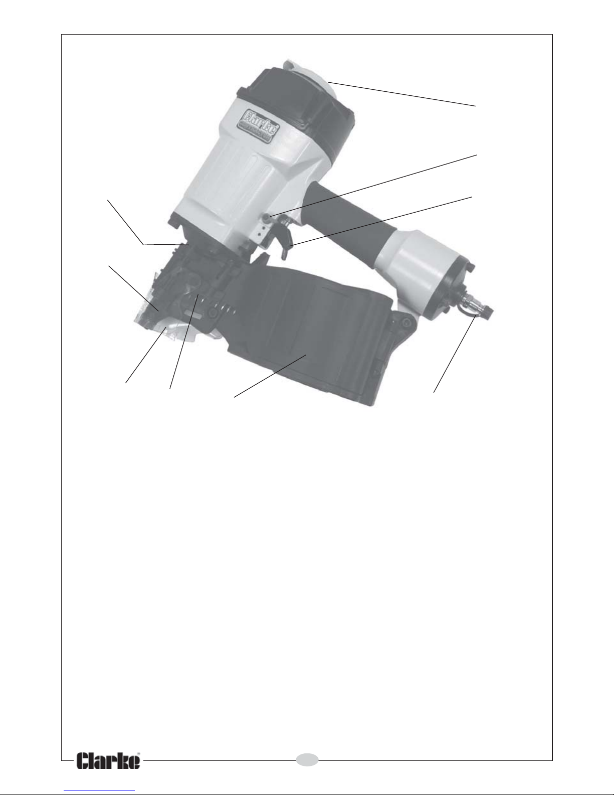
1. Nail Magazine
2. Drive Pawl
3. Protective Screen
4. Safety Yoke (muzzle)
5. Mode Switch (single/full contact sequential actuation)
6. Trigger
7. Pressure Adjuster
8. Compressed Air Hose Connector
9. Exhaust Deflector
1
2
3
4
9
8
7
6
5
Page 5

5
GENERAL SAFETY PRECAUTIONS
WORK AREA
1. ALWAYS Keep the work area clean and well lit. Floors should always be
kept clear. Cluttered or dark areas invite accidents.
2. ALWAYS keep children and bystanders away while operating a power tool.
Distractions can cause loss of control.
PERSONAL SAFETY
1. ALWAYS stay alert, watch what you are doing and use common sense
when operating a power tool. Do not use a power tool while you are tired
or under the influence of medication, drugs or alcohol. A moment of
inattention can result in personal injury.
2. ALWAYS use safety equipment when operating this tool. Always wear
suitable protective clothing and eye protection including industrial gloves,
ear defenders and approved impact resistant safety glasses. (Eye glasses
are NOT safety glasses)
3. NEVER over-reach. Keep your proper footing and balance at all times to
enable better control of the machine in unexpected situations.
4. NEVER point the tool at anyone or any part of your own body. Keep all
parts of your limbs behind the safety guard at all times.
5. ALWAYS keep a safe distance between yourself and others when using
the tool.
6. NEVER attempt any repairs yourself. If you have a problem with the
machine contact your local Clarke dealer.
7. ALWAYS store power tools out of reach of children.
8. ALWAYS dress properly. Never wear loose clothing or jewellery which could
be caught on moving parts.
GENERAL POWER TOOL USE AND CARE
1. NEVER force or misuse the tool. It will do a better and safer job at the rate
for which it was designed.
2. ALWAYS maintain the tool with care and keep it clean for best / safest
performance.
3. NEVER use this tool if any part is damaged. Have it inspected and repaired
by a competent technician.
4. NEVER modify this tool in any way. Use it ONLY for the purpose for which it
is designed.
5. NEVER carry the tool with your finger on the trigger. The nailer is fitted with
a safety yoke mechanism to prevent accidental firing.
Page 6

6
6. ALWAYS disconnect the tool from the air supply when not in use, and
before carrying out any maintenance or re-loading with fresh nails.
7. ALWAYS Store the tool out of reach of children.
8. NEVER allow persons unfamiliar with these instructions to operate this tool.
SERVICING
1. ALWAYS have power tools serviced by your Clarke dealer, using only
identical replacement parts. This will ensure the safety of the power tool is
maintained.
COIL NAILER SAFETY INSTRUCTIONS
1. Although the Coil Nailer is water resistant and may be used outdoors, DO
NOT leave it exposed to the elements. Avoid direct sunlight, direct heat,
rain/moisture etc.
2. ALWAYS keep the air hose away from the nailer and ensure that the
operator is not restricted by the length of the hose.
3. ALWAYS take care when a long air hose is required in the work area as it
presents a trip hazard. Coil the hose away as soon as the job is finished.
4. NEVER abuse hoses or connectors. NEVER carry a tool by the hose, or yank
it to disconnect from the air supply. Keep hoses away from heat, oil and
sharp edges. Check hoses for leaks or worn condition before use, and
ensure that all connections are secure.
5. NEVER use with an air supply greater than 8.2 bar (120 PSI).
6. NEVER use any other type of gas such as bottled oxygen or other bottled
gas as a power source to operate this tool. Use compressed air ONLY.
7. NEVER load the tool with the trigger depressed in case of accidental firing.
8. NEVER fire tool at an incline. It must be perpendicular to the work surface.
9. NEVER drive in nails at the edge of a work surface, as the edge could fail
and fly off, endangering yourself or others in the vicinity.
10. ALWAYS take care not to fire a nail into an existing metal fastening in case
the nail should ricochet causing personal injury.
11. NEVER operate the tool unless the safety nose is in contact with the
workpiece, or without any nails or damage to the tool could result.
12. ALWAYS keep hands away from the nose of the tool when connecting to
the compressed air supply.
13. ALWAYS ensure only the correct nails are used, as specified for this tool.
Page 7
7
THE COMPRESSED AIR SUPPLY
WARNING: COMPRESSED AIR CAN BE DANGEROUS. ENSURE THAT YOU
ARE THOROUGHLY FAMILIAR WITH SAFETY PROCEDURES RELATING TO
THE USE OF COMPRESSORS AND COMPRESSED AIR SUPPLIES.
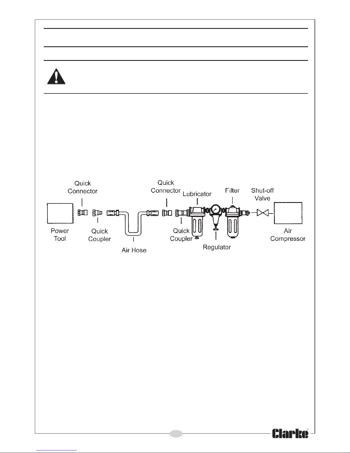
A filtered, lubricated and regulated air supply will be required as shown in the
layout below.
Ensure the pressure available is within the range of 70-100 psi. Higher pressure
or contaminated air will shorten the tool’s life because of increased wear,
and could be a safety hazard. Higher pressure will also increase the noise
level.
The air inlet used for connecting the air supply has a standard ¼” BSP thread.
For best performance, a quick-fit connector can be used at each end of the
line.
Line pressure, or hose internal diameter should be increased to compensate
for unusually long air hoses (over 10m). Minimum hose diameter should be
6mm (¼”) ID, and fittings should have the same internal dimensions.
Check the quality of the compressed air supply before starting work. Water in
the air line will cause damage to the tool, and a dirty filter will reduce the
available air pressure.
Ensure there are no leaks in any of the connections.
Page 8
8
LOADING THE COIL NAILER
WARNING: ENSURE THE COMPRESSED AIR SUPPLY IS DISCONNECTED
BEFORE ATTEMPTING TO LOAD THE COIL NAILER. DO NOT HOLD THE
TRIGGER WHILE LOADING THE NAILER.
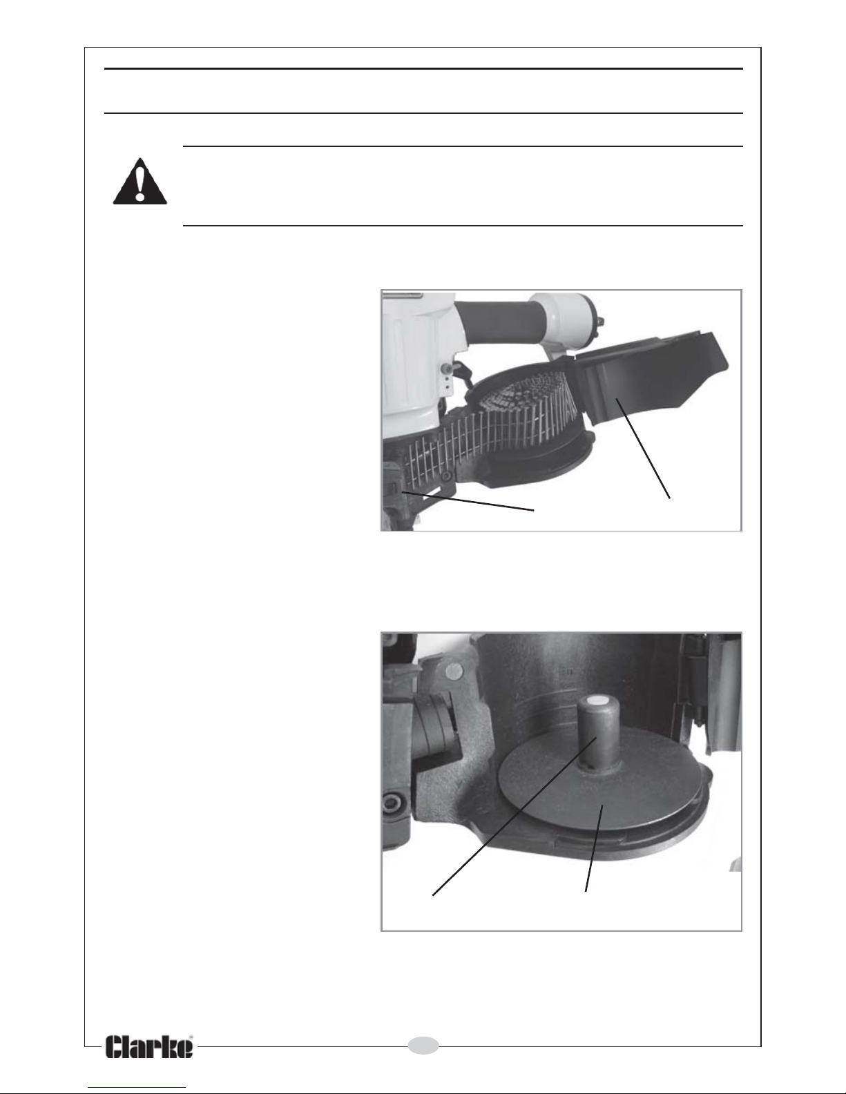
The machine is loaded with nails as follows:
1. Press the latch (1) open
and pull the magazine
cover (2) back.
2. Knowing the nail size to be
used, raise and twist the
adjuster 90 degrees for the
chosen nail size as
required.
3. Insert a strip of nails into
the magazine, (pointed
end downwards), taking
care that the strip is wound evenly around the centre spigot (3) of the
height adjuster (4). Note that 3 different nail sizes can be used, as indicated by the markings on
the inside of the magazine. The sizes available
are listed on page 12.
4. Take care when handling
the nails, that they do not
become bound together.
1 2
3 4
Page 9
9
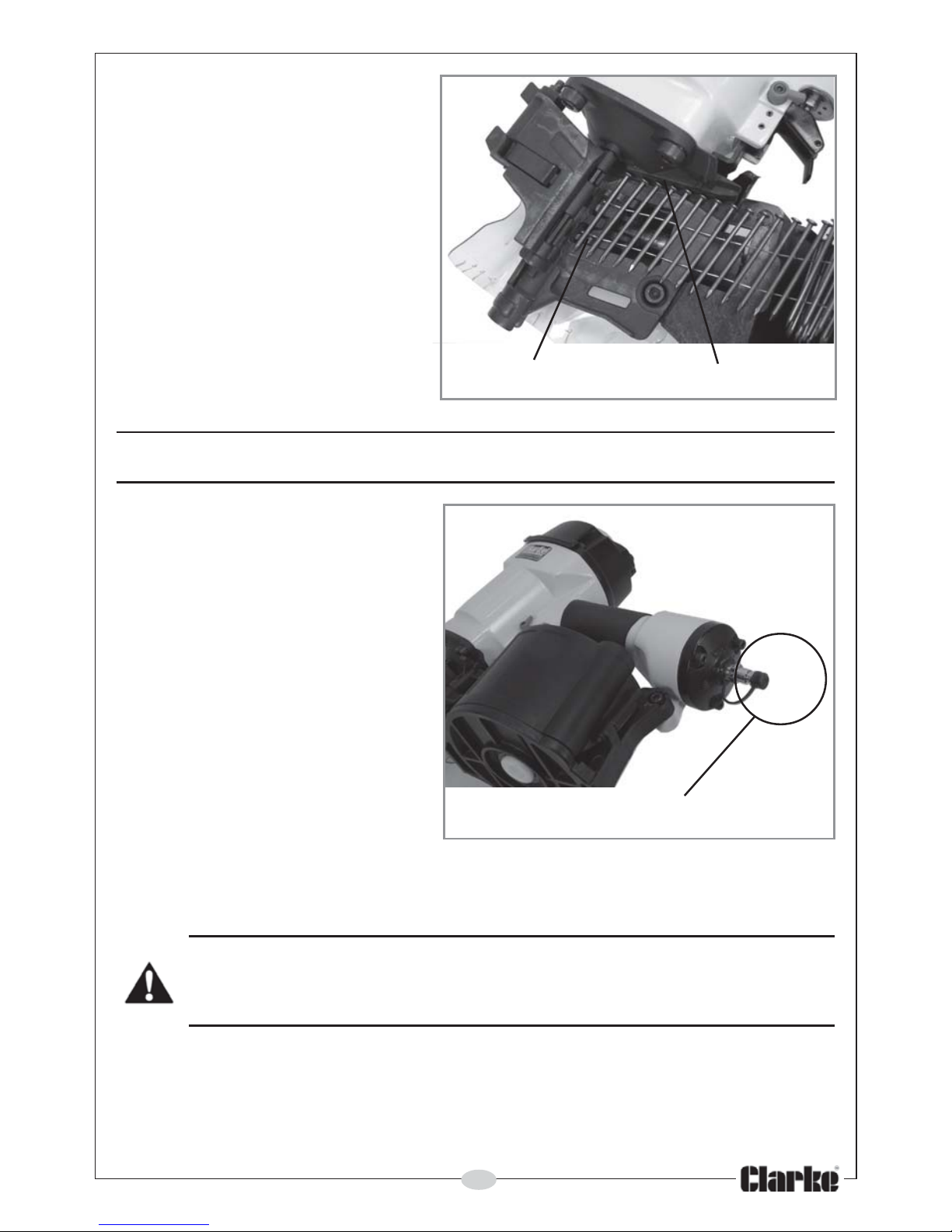
5. Offer the end of the strip of
nails into the gun, taking
care that the nail heads lay
flat in the groove (5) closest
to the machine body and
that the first nail in the strip is
resting in the drive pawl (6).
6. Close the magazine cover
and close the latch.
• This will not be possible if the
nails are not positioned
correctly. The machine is
now ready to use.
6 5
OPERATION
1. Connect the nailer to the air
supply. With the air supply
turned OFF, connect the air
line to the ¼” BSP connector.
(A Whip Hose with quick-fit
coupling is available from
your Clarke dealer).
2. Turn ON the air supply.
• Check for air leaks. If any are
apparent, rectify before
proceeding.
3. Ensure the operating pressure
is set to between 70-100psi .
This may be adjusted,
dependant upon the density of the workpiece. The harder the target
material, the higher the air pressure required. e.g. When nailing into
softwoods, a pressure of only 70psi may be all that is required.
Quick release Airline Connection
NEVER OPERATE THE TOOL UNLESS THE SAFETY YOKE IS IN CONTACT
WITH THE WORKPIECE, OR WITHOUT ANY NAILS OR DAMAGE TO THE
TOOL COULD RESULT.
Page 10
10
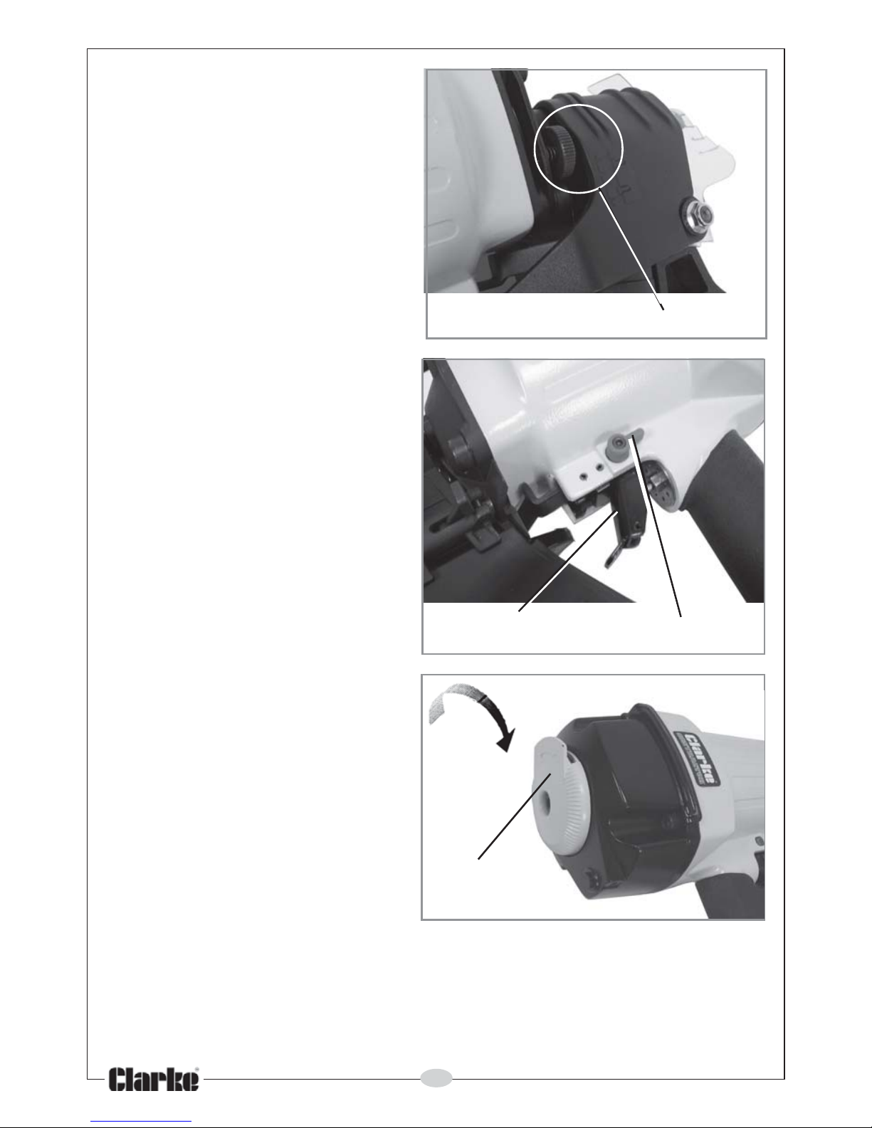
4. Before starting work, test the
nailer on a piece of scrap
wood to check that the driving
depth is correct. If the nails are
being driven too far or not
deep enough into the timber,
adjust the air pressure adjuster
located on the side of the nose
section accordingly.
(Remember; whatever pressure
adjustment is to be carried out
on the tool is dependant upon
the pressure received from the
airline).
5. Hold the tool so that it is at
right angles to the workpiece.
Lower it so that the yoke
contacts the work surface
and with a slight downwards
pressure, pull the trigger to
drive in the nail.
6. The machine is equipped with
a switch that can change the
operating mode from single
shot to sequential shots. When
the red switch is pointing
towards the operator, the coil
nailer will fire a single nail only.
To fire the next nail the trigger
must be released. When the
switch is pointing away from the
operator, the nailer can fire
sequentially.
7. An adjustable exhaust deflector
is fitted. Turn the deflector into
any chosen position to avoid
the blast from the exhaust.
CLEARING A JAM
Should the coil nailer jam; for example, with the last nail of a batch,
disconnect the air supply and pull the trigger to ensure the air line is not under
pressure. Open the magazine and latch and clear the jam before re-loading.
Deflector
Pressure adjuster
Trigger Mode Switch
Page 11
11
MAINTENANCE
WARNING: ENSURE THE COMPRESSED AIR SUPPLY IS DISCONNECTED
BEFORE ATTEMPTING ANY MAINTENANCE ON THE COIL NAILER.
DAILY BEFORE USE
1. Check and clean, if necessary, the air inlet gauze filter located inside the
air hose connection point.
2. A bottle of Clarke airline oil is supplied with the Coil Nailer. Unscrew the
cap & withdraw the nozzle which is reversed within the neck of the bottle.
Screw the cap and nozzle correctly into place and squirt a few drops of
oil, into the air inlet. This should be carried out regardless of whether or not
an air line lubricator is used.
3. Inspect the tool for worn or damaged parts, or for any loose screws or
bolts.
4. Examine the trigger mechanism for free movement.
5. Keep magazine and yoke of the tool free of grime or abrasive particles.
6. If working conditions are below freezing it is advisable to keep air tools
warm by storing them in a warmer place.
DURING USE
For lubricating the internal components when in operation, an airline
lubricator should be used, with Clarke Airline Oil, adjusted to 2 drops per
minute.
If an airline lubricator is NOT used, this procedure should be repeated after
every two to three hours of use.
Make a regular inspection of the trigger, spring and safety mechanism for free
movement.
AIRLINE WORKING CONDITIONS
Be aware that factors other than the tool’s condition may effect it’s
operation and efficiency. Anything which will reduce the air supply, such as
reduced compressor output, excessive demand on the airline, moisture or
restrictions in the line, or the use of connectors of improper size or poor
condition will all reduce tool performance.
Page 12
12
Grit or gum deposits in the tool may also reduce efficiency. This condition can
be corrected by cleaning the air strainer and flushing out the tool with gum
solvent oil, or failing this, the tool should be dismantled, thoroughly cleaned,
dried and reassembled. This is a task for your Clarke dealer.
If the tool runs erratically or becomes inefficient, and the air supply is sound, it
will be necessary to dismantle the piston assembly and replace worn or
damaged parts, which is best carried out by your Clarke dealer.
STORAGE
If the Coil Nailer is to be stored, or is idle for longer than 24 hours, run a few
drops of Clarke airline oil into the air inlet before storing.
Ensure the protective cap is replaced on the airline connector, once the
airline is disconnected.
ACCESSORIES & CONSUMABLES
A wide range of airline accessories is available, including Filter/Regulators.
Lubricators, High Pressure Hoses from 5 to 100 metres, Whip Hoses etc.
Contact your Clarke dealer for further information, or Clarke International
Sales Department on 01992 565333.
Wire-collated nails are available for the CON15 in three sizes:
Part No Nail Size
1800462 2.3 x 44mm Nails (300pcs)
1800464 2.5 x 50mm Nails (300pcs)
1800466 2.9 x 70mm Nails (250pcs)
Clarke airline oil (1 litre) is available from your Clarke dealer; Part No 3050825
IMPORTANT: The use of parts other than genuine Clarke replacement parts
may result in safety hazards, decreased tool performance and will invalidate
your warranty.
Page 13
13
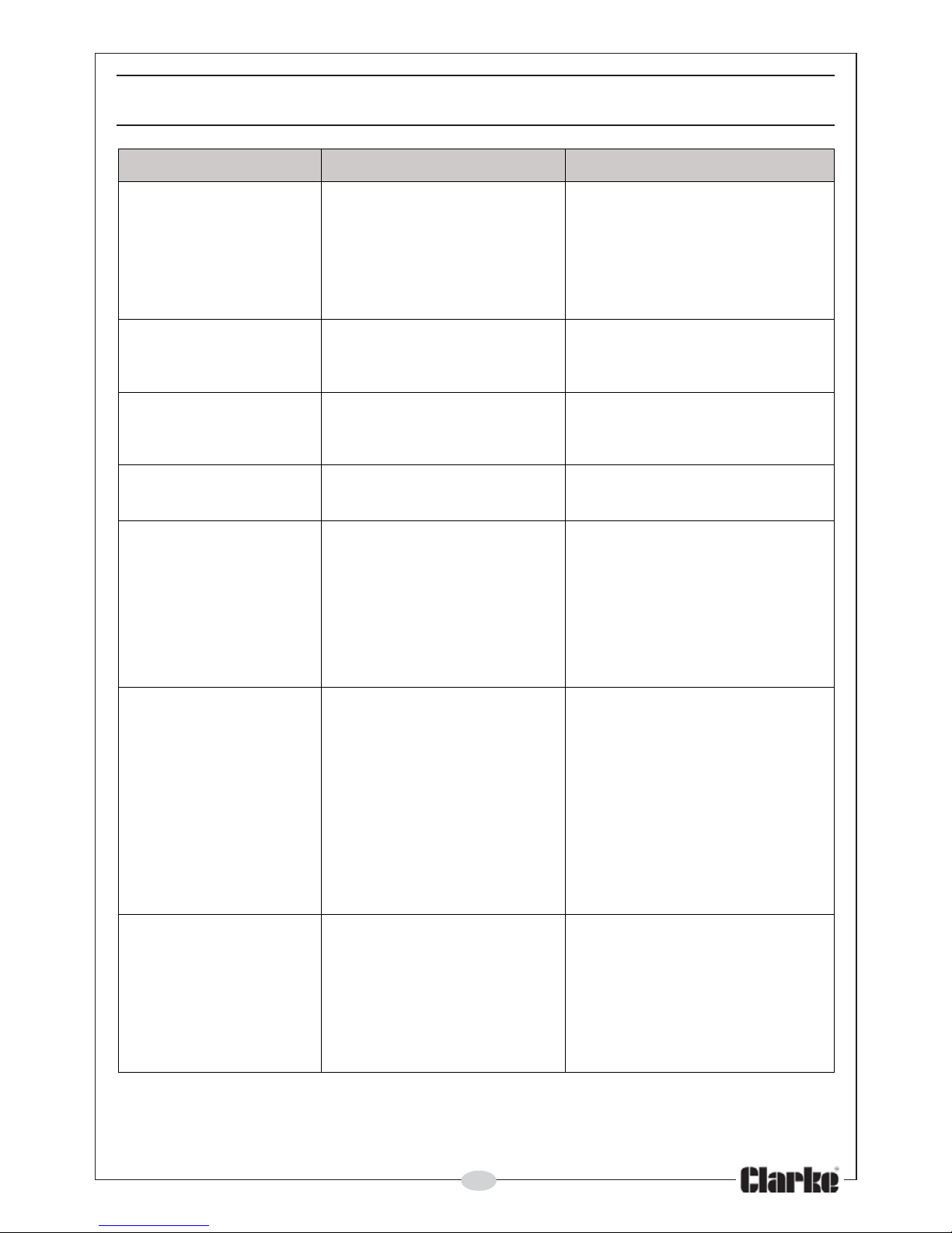
TROUBLESHOOTING
MOTPMYS MELBORP NOITULOS
fopotraenkaelriA
rolootreggirtehtni
.aera
evlavreggirtnignir-O.1
.degamadaera
sidaehevlavreggirT.2
.
degamad
laes,metsevlavreggirT.3
.degamaderagnir-Oro
gnir-Oecalper&enimaxE.1
.ecalper&enimaxE.2
reggirtecal
perdnaenimaxE.3
.gnir-Orolaes,metsevlav
fomottobraenkaelriA
.loot
.swercsesooL.1
gnir-OdegamadronroW.2
.rep
mubro
swercsnethgiT.1
gnir-Oecalper&enimaxE.2
.repmubro
ydobneewtebkaelriA
.pacrednilycdna
swercsesooL.1..
-O
degamadronroW.2
slaesrosgnir..
.swercsnethgiT.1
gnir-Oecalper&enimaxE.2
.repmubro
nevirdgnieberasliaN
.peedo
otni
.repmubnroW.1
.hgihootteserusserpriA.2
.repmubecalpeR.1
.erusserpriatsujdA.2
lianevirdtonseodlooT
gnit
areposirollew
.ylhsigguls
.ylppusriaetauqedanI.1
.noitacirbuletauqedanI.2
gnir-OdegamadronroW.3
.laesro
red
nilycnitroptsuahxE.4
.dekcolbsidaeh
ylppusriaetauqedamrifnoC.1
otniliofospord6-2tresnI.2
.telniria
gnir-Oe
calper&enimaxE.3
.laesro
degamadecalpeR.4
.straplanretni
ehtllaerifotsliaflooT
.nrutnislian
rorepmubnroW.1
g
nirpsdegamad.
.etalptnorfnitriD.2
egamadroemirG.3
gnivommorfslianspots
.enizagamniyleerf
nognir-OyrdronroW.
4
.noitacirbulfokcal/,notsip
laesrevocrednilyC.5
.gnikael
rorepmubecalpeR.1
.gnirpsrehsup
nolennahcevirdnae
lC.2
.etalptnorf
fotuoemirgnaelC.3
.enizagam
.gnir-Oecalper&enimaxE.4
.rehsawgnilaesecalpeR.5
.smajlooTdegam
adrotcerrocnI.1
.srenetsaf
revirdnrowrodegamaD.2
.ediug
wercsesonroenizagaM.3
.esool
.ytridsienizagaM.4
tcerrocesudnaegnahC.1
.srenetsaf
ehtecalperdnaenimaxE.2
.revird
.enizagamehtnethgiT.3
.enizagamehtnaelC.4
In the event that any of the above situations occurs, requiring the dismantling
and overhaul of the tool, contact your Clarke International Service
Department on 020-8988-7400.
Page 14
14
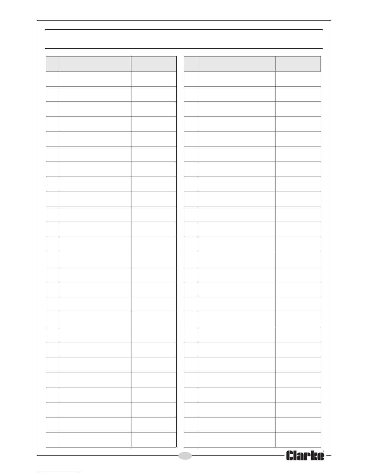
PARTS LIST
oN
noitpircseD
oNtraP
oN noitpircseD
oNtraP
1
tloB10051NOCTH62gniR-OevlaV62051NOCTH
2
rotcelfeDriA20051NOCTH72gniR-O72051NOCTH
3
etalPgnirpS30051NOCTH82eve
elSevlaV82051NOCTH
4
tloBrednilyC40051NOCTH92gniR-O92051NOCTH
5
tloBxeH50051NOCTH03gniR-O03051NOCTH
6
rotcetorPydoBn
uG60051NOCTH13gniR-O13051NOCTH
7
revoCrednilyC70051NOCTH23gnirpSreggirT23051NOCTH
8
tloBdedaeHxeH80051NOCTH33eloPreg
girT33051NOCTH
9
rehsaWgnirpS90051NOCTH43sgniR-O43051NOCTH
01
esaBgnirpS01051NOCTH53sgniR-O53051NOCTH
11
gnirpSevlaV
ecnalaB11051NOCTH63bonKhctiwS63051NOCTH
21
ylbmessAevlaVecnalaB21051NOCTH73niP73051NOCTH
31
ralloC31051NOCTH83esaBgn
idilS83051NOCTH
41
gniR-O41051NOCTH93reggirT93051NOCTH
51
edalBrevirD51051NOCTH04esoNytefaS04051NOCTH
61
gniR-O61051N
OCTH14niP14051NOCTH
71
gniRdexiF71051NOCTH24niPgnitsujdA24051NOCTH
81
gniR-O81051NOCTH34gnirpS34051NOCTH
91
gniR-O91051
NOCTH44paC44051NOCTH
02
rednilyC02051NOCTH54tloBxeH54051NOCTH
12
rehsaWrepmuBedistuO12051NOCTH64tloB64051NOCTH
22
rehs
aWrepmuBedisnI22051NOCTH74gniR-O74051NOCTH
32
etalPrevoCrednilyC32051NOCTH84gniR-O84051NOCTH
42
ydoBnuG42051NOCTH94e
diuGrevirD94051NOCTH
52
gniR-O52051NOCTH05bonKgnitsujdA05051NOCTH
Page 15
15
PARTS LIST
oN
noitpircseD
oNtraP
oN noitpircseD
oNtraP
15
tloBgnitsujdA15051NOCTH67enizagaM67051NOCTH
25
gnirpSnoisserpmoC25051NOCTH77revoCenizagaM77051NOCTH
53
tlo
BgnitsujdA35051NOCTH87livnA87051NOCTH
45
tloBxeH45051NOCTH97kooHgnirpS-297051NOCTH
55
lwaP55051NOCTH08etalPgnitsujdA0
8051NOCTH
65
gnirpSlwaP65051NOCTH18etalPmuinimulA18051NOCTH
75
niP75051NOCTH28eveelSgnitsujdA28051NOCTH
85
niP-38505
1NOCTH38esaBgnitsujdAhtpeDliaN38051NOCTH
95
gniR-O95051NOCTH48rehsaWrebbuR48051NOCTH
06
notsiP06051NOCTH58gnirpS5805
1NOCTH
16
gniR-O16051NOCTH68tloBxeH68051NOCTH
26
gnirpS26051NOCTH78tloB-278051NOCTH
36
rehsaWpmuBnotsiP36051NOCTH88tlo
BxeH88051NOCTH
46
esaBgnirpS46051NOCTH98gniRdexiF98051NOCTH
56
reniateRpanS56051NOCTH09revoCdaeHliaN09051NOCTH
66
dr
aoBrevoC66051NOCTH19mliFevitcetorP19051NOCTH
76
doRgnicennoC76051NOCTH29rehsaW29051NOCTH
86
gnirpSnoisserpmoC86051
NOCTH39rehsaWrebbuRdexiF39051NOCTH
96
lwaP96051NOCTH49pirG49051NOCTH
07
niP07051NOCTH59rehsaWetalPdnE59051NOCTH
17
gni
rpSnoisserpmoC17051NOCTH69etalPdnE69051NOCTH
27
niP27051NOCTH79rehsaWgnipS79051NOCTH
37
niP37051NOCTH89tloBdedaeHxeH8
9051NOCTH
47
gnirpSnoisserpmoC47051NOCTH99gulPtelnIriA99051NOCTH
57
dnatSytefaS57051NOCTH001paCgulP00151NOCTH
Page 16
16
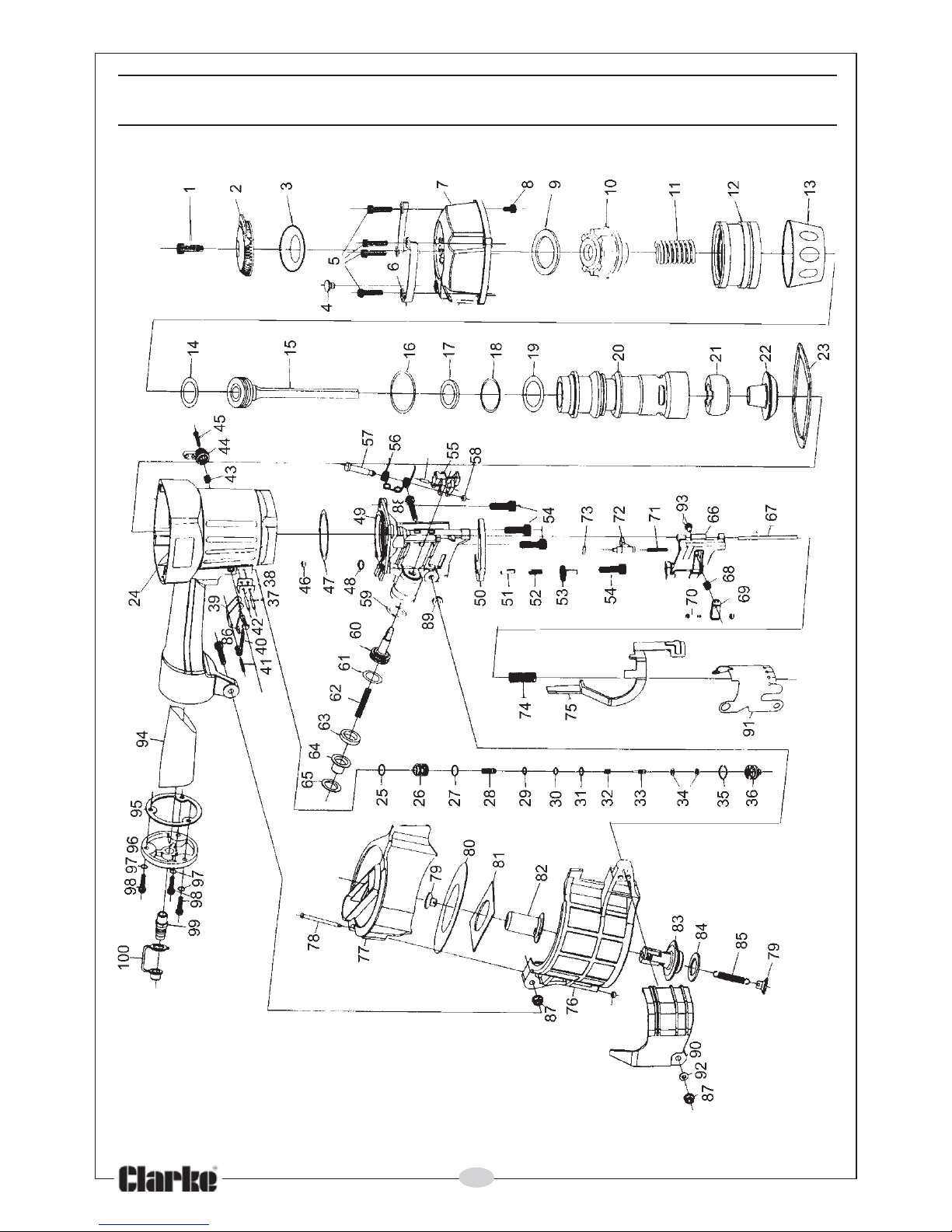
PARTS DIAGRAM
Page 17
17
VIBRATION EMISSIONS
MODEL No: CON15
DESCRIPTION: COIL NAILER
Declared vibration emission value in accordance
with EN12096
Measured vibration emission value -
a:
3.3m/s
2
Uncertainty value -
K:
3.5m/s
2
Values determined according to EN28622-1
Employers are advised to refer to the HSE publication “Guide for Employers”.
All hand held power tools vibrate to some extent, and this vibration is
transmitted to the operator via the handle, or hand used to steady the tool.
Vibration from about 2 to 1500 herz is potentially damaging and is most
hazardous in the range from about 5 to 20 herz.
Operators who are regularly exposed to vibration may suffer from Hand Arm
Vibration Syndrome (HAVS), which includes ‘dead hand’, ‘dead finger’, and
‘white finger’. These are painful conditions and are widespread in industries
where vibrating tools are used.
The health risk depends upon the vibration level and the length of time of
exposure to it……in effect, a daily vibration dose.
Tools are tested using specialised equipment, to approximate the vibration
level generated under normal, acceptable operating conditions for the tool
in question. For example, a grinder used at 45° on mild steel plate, or a
sander on softwood in a horizontal plane etc.
These tests produce a value ‘a
’
, expressed in metres per second per second,
which represents the average vibration level of all tests taken, in three axes
where necessary, and a second figure ‘K’, which represents the uncertainty
factor, i.e. a value in excess of ‘a’, to which the tool could vibrate under
normal conditions. These values appear in the specification panel below.
HAND-ARM VIBRATION
Page 18
18
You will note that a third value is given in the specification - the highest
measured reading in a single plane. This is the maximum level of vibration
measured during testing in one of the axes, and this should also be taken into
account when making a risk assessment.
‘
a
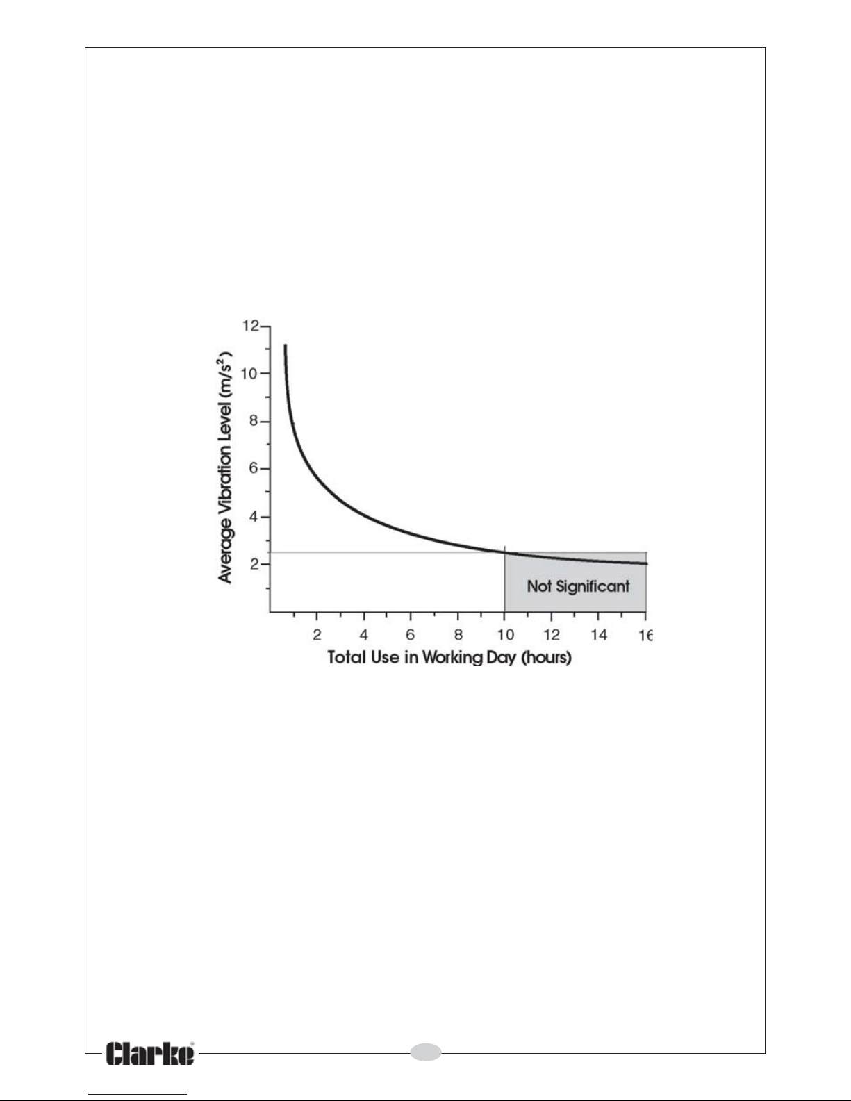
’ values in excess of 2.5 m/s2 are considered hazardous when used for
prolonged periods. A tool with a vibration value of 2.8 m/s2 may be used for
up to 8 hours (cumulative) per day, whereas a tool with a value of 11.2 m/s
2
may be used for ½ hour per day only.
The graph below shows the vibration value against the maximum time the
respective tool may be used, per day.
The uncertainty factor should also be taken into account when assessing a
risk. The two figures ‘
a
’ and ‘K’may be added together and the resultant
value used to assess the risk.
It should be noted that if a tool is used under abnormal, or unusual conditions,
then the vibration level could possibly increase significantly. Users must always
take this into account and make their own risk assessment, using the graph
above as a reference.
Some tools with a high vibration value, such as impact wrenches, are
generally used for a few seconds at a time, therefore the cumulative time
may only be in the order of a few minutes per day. Nevertheless, the
cumulative effect, particularly when added to that of other hand held power
tools that may be used, must always be taken into account when the total
daily dose rate is determined.
Page 19
19
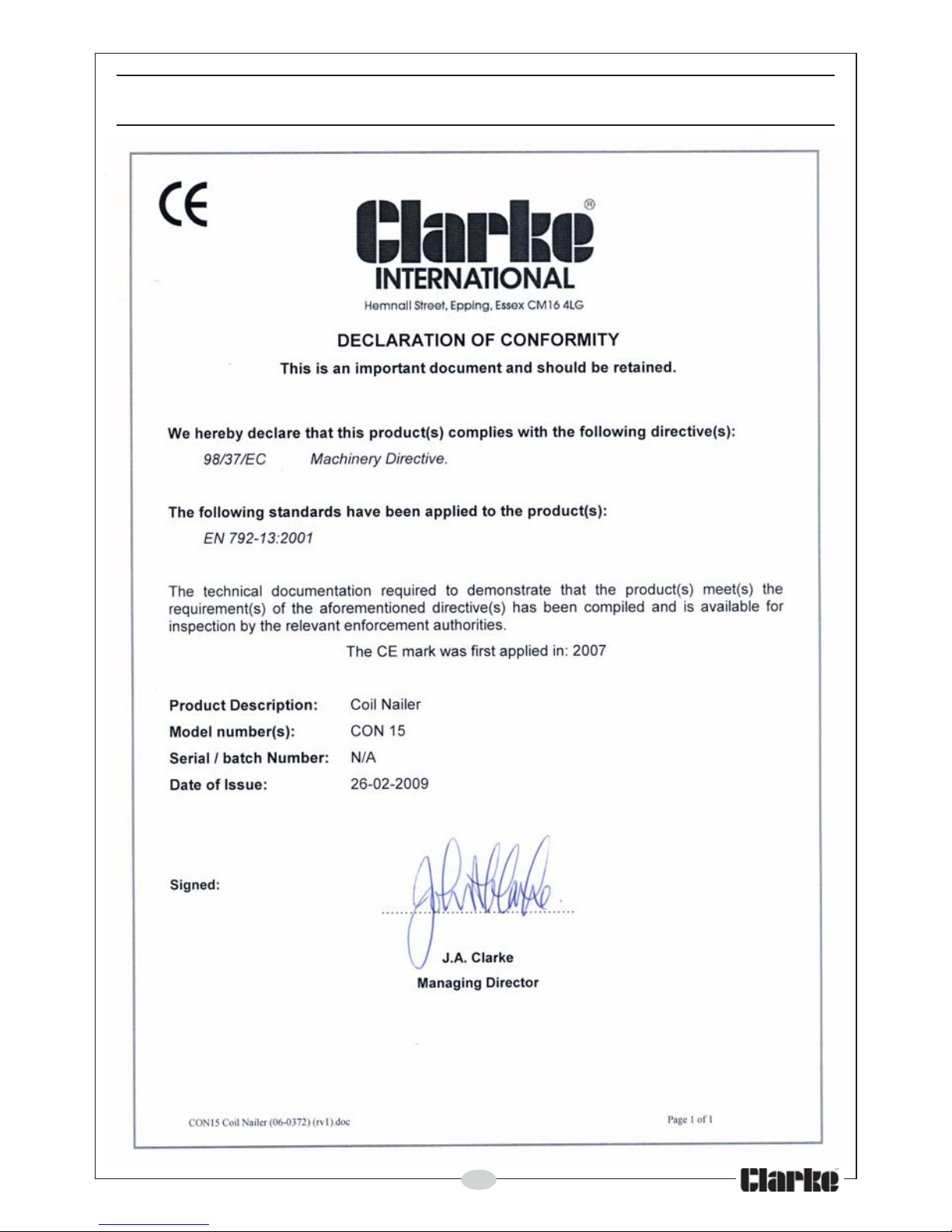
DECLARATION OF CONFORMITY
Page 20

 Loading...