

Page 1

1
OPERATING & MAINTENANCE
INSTRUCTIONS
LS0610
Part No. 6460200
RECIPROCATING SAW
MODEL No. CON100
Part No. 6459000
RECIPROCATING SAW
Page 2

2
Thank you for purchasing this CLARKE Reciprocating Saw.
Before attempting to use the reciprocating saw, please read this manual
thoroughly and follow the instructions carefully. In doing so you will ensure the
safety of yourself and that of others around you, and you can look forward to
the reciprocating saw giving you long and satisfactory service.
GUARANTEE
This product is guaranteed against faulty manufacture for a period of 12
months from the date of purchase. Please keep your receipt which will be
required as proof of purchase.
This guarantee is invalid if the product is found to have been abused or
tampered with in any way, or not used for the purpose for which it was
intended.
Faulty goods should be returned to their place of purchase, no product can
be returned to us without prior permission.
This guarantee does not effect your statutory rights.
FEATURES
• Variable speed reciprocating saw • 3 stage pendulum action
SPECIFICATIONS
Model number................................................... CON100
Rated voltage ...................................................230V AC 50Hz
Input power ....................................................... 600 Watts
No load variable speed ................................... 700 - 2300 strokes per minute
Pendulum action .............................................. 3 stage
Cutting capacities ............................................ Metal - 10 mm
............................................................................. Wood - 150 mm
Sound pressure level ......................................... 95.02 dB (A)
Sound power level ............................................106.02 dBLwA
Please note that the details and specifications contained herein, are correct at the time of going to print. However, CLARKE
International reserve the right to change specifications at any time without prior notice.
Page 3
3
GENERAL SAFETY PRECAUTIONS
WARNING:
As with all machinery, there are certain hazards involved with their
operation and use. Exercising respect and caution will considerably
lessen the risk of personal injury. However, if normal safety
precautions are overlooked or ignored, personal injury to the
operator or damage to property, may result.
1. ALWAY S Learn the machines’ applications, limitations and the specific potential
hazards peculiar to it. Read and become familiar with the entire operating manual.
2. ALWAYS use a face or dust mask if operation is particularly dusty.
3. ALWAYS check for damage. Before using the machine, any
damaged part, should be checked to ensure that it will operate
properly, and perform its intended function. Check for alignment
of moving parts, breakage of parts, mountings, and any other
condition that may affect the machines’ operation. Any damage
should be properly repaired or the part replaced. If in doubt, DO
NOT use the machine. Consult your local dealer.
4. ALWAYS disconnect the tool/machine from the power supply before servicing and
when changing accessories.
5. ALWAYS wear safety goggles, manufactured to the latest European Safety
Standards. Everyday eyeglasses do not have impact resistant lenses, they are not
safety glasses.
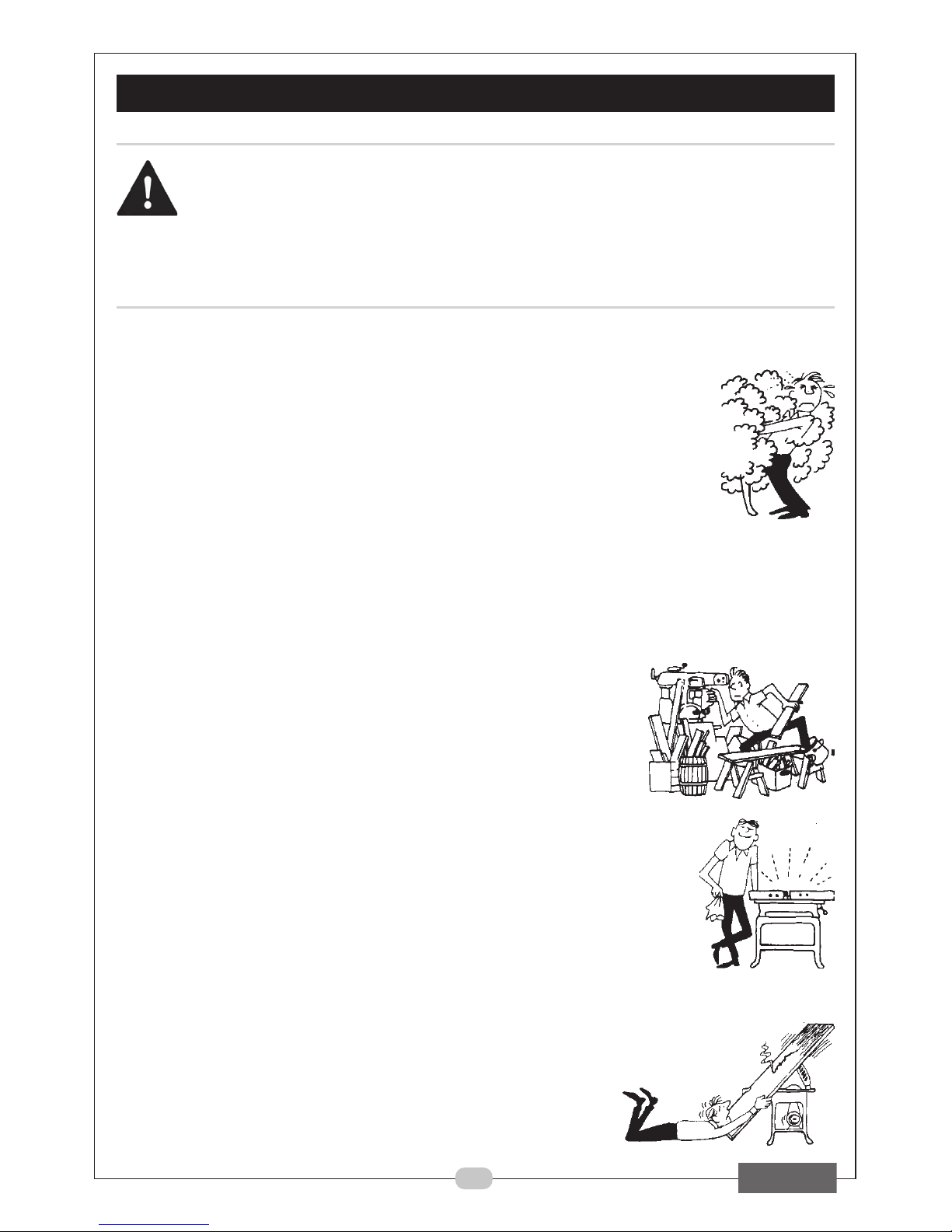
6. ALWAYS keep work area clean. Cluttered areas and benches invite accidents.
7. ALWAYS ensure that adequate lighting is available. A minimum intensity of 300 lux
should be provided. Ensure that lighting is positioned that
you will not be working in your own shadow.
8. ALWAYS keep children away. All visitors should be kept a
safe distance from the work area, especially whilst
operating the machine.
9. ALWAYS maintain machine in top condition. Keep tools/
machines clean for the best and safest performance.
Follow maintenance instructions.
10. ALWAYS handle with extreme care do not carry the tool/
machine by its’ electric cable, or yank the cable to disconnect
it from the power supply .
11. ALWAYS ensure the switch is off before plugging in to mains.
Avoid accidental starting.
12. ALWAYS concentrate on the job in hand, no matter how trivial it
may seem. Be aware that accidents are caused by
carelessness due to familiarity.
13. ALWAYS keep your proper footing and balance at all times don’t overreach. For
best footing, wear rubber soled footwear. Keep floor
clear of oil, scrap wood, etc.
14. ALWAYS wear proper apparel. Loose clothing or
jewellery may get caught in moving parts. Wear
protective hair covering to contain long hair.
15. ALWAYS use recommended accessories. The use of
improper accessories could be hazardous.
Page 4

4
GENERAL SAFETY PRECAUTIONS
16. ALWAYS remove plug from electrical outlet when
adjusting, changing parts, or working on the machine.
17. NEVER operate machine while under the influence of
drugs, alcohol or medication.
18. NEVER leave machine running unattended. Turn power off.
Do not leave the machine until it comes to a complete
stop.
19. NEVER force the machine. It will do a better and safer job at
the rate for which it was designed.
20. NEVER use power tools in damp or wet locations or expose
them to rain. Keep your work area well illuminated. Do not
use in explosive atmosphere (around paint fumes,
flammable liquids etc.). Avoid dangerous environments.
ADDITIONAL WARNINGS FOR RECIPROCATING
SAWS
1. ALWAYS wear ear protectors/defenders as the noise level of this machine can
exceed 85dB (A).
2. ALWAYS use the appropriate blade for the material being cut.
3. ALWAYS keep the mains cable well away from the machine and ensure an
adequate electrical supply is close at hand so that the operation is not restricted by
the length of the cable.
4. ALWAYS switch the machine OFF immediately the task is completed.
5. ALWAYS ensure the blade is fully tightened before use.
6. ALWAYS allow sufficient clearance beneath the work to ensure the blade does not
come into contact with the floor, table etc.
7. ALWAYS check for hidden electrical wires or water pipes etc.
8. NEVER allow the ventilation slots in the machine to become blocked.
9. DO NOT cut material above the specified thickness.
10. DO NOT cut through walls or cavities before checking for hidden electrical wires or
water pipes etc.
11. DO NOT touch the blade immediately after use, allow time for it to cool.
12. DO NOT cut work less than at least twice the pitch of the saw blade. i.e. at least two
teeth must be in contact with the work at all times.
13. DO NOT use the machine if the electric cable, plug or motor is in poor condition.
14. When cutting wood, ensure all nails have been removed beforehand. Nails will
damage the wood saw blade.
15. When cutting metals, always use a cooling agent i.e. cutting/soluble oil.
Additionally, please keep these instructions in a safe place for future reference.
Page 5
5
ELECTRICAL CONNECTIONS
This product is provided with a standard 13 amp, 230 volt (50Hz), BS 1363 plug,
for connection to a standard, domestic electrical supply. Should the plug
need changing at any time, ensure that a plug of identical specification is
used.
WARNING!
This appliance is double insulated, and the two wires in the mains lead should
be wired in accordance with the following colour code:
BLUE - NEUTRAL
BROWN - LIVE
•
Connect the BLUE coloured wire to the plug terminal marked with a letter “N”
• Connect the BROWN coloured wire to the plug terminal marked with a letter “L”
If this appliance is fitted with a plug which is moulded on to the electric cable
(i.e. non-rewireable) please note:
1. The plug must be thrown away if it is cut from the electric cable. There is
a danger of electric shock if it is subsequently inserted into a socket
outlet.
2. Never use the plug without the fuse cover fitted.
3. Should you wish to replace a detachable fuse carrier, ensure that the
correct replacement is used (as indicated by marking or colour code).
4. Replacement fuse covers can be obtained from your local Clarke
dealer or most electrical stockists.
FUSE RATING
The fuse in the plug must be replaced with one of the same rating (5 amps)
and this replacement must be ASTA approved to BS1362.
If in doubt, consult a qualified electrician. Do not attempt any electrical
repairs yourself.
CABLE EXTENSION
Always use an approved cable extension suitable for the power rating of this
tool (see specifications), the conductor size should also be at least the same
size as that on the machine, or larger. When using a cable reel, always unwind
the cable completely. If using tool outdoors, only use extension cables
intended for outdoor use.
Page 6

6
BEFORE USE
FITTING THE BLADE
WARNING!
Before removing, or installing a blade, make sure that the mains
plug has been removed from the mains supply.
1. Loosen the blade securing screw,
using the hexagonal key provided.
2. With the blade teeth facing
downwards, push the blade shank into
the blade locating clip as far as
possible.
3. Fully tighten the blade securing screw.
ADJUSTING THE SHOE
1. The shoe can be adjusted by loosening the shoe adjustment screws and
sliding the shoe in or out.
2. Re-tighten all screws before use.
VARIABLE SPEED SELECTOR
The variable speed selector is used to control the speed of the reciprocating
saw.
• The higher the number selected the faster the stroke rate of the blade.
• The stroke rate should be changed according to the material being cut.
This is only a recommendation, you should always make a test cut on a
scrap piece of material first.
Blade securing screw
Shoe adjustment screws
Variable speed
selector
LAIRETAM
DEDNEMMOCER
GNITTESDEEPS
dooWXAM-5
lateM3-2
muinimulA5-3
CVP4-3
Page 7

7
OPERATION
ON/OFF SWITCH
1. Slide the trigger switch down and
back.
The saw will run at the speed
selected with the variable speed
selector.
2. To switch off the reciprocating saw,
release the trigger switch.
WARNING!
The blade will continue to run for a short period after the trigger has
been release. Wait until it stops before removing it from the
workpiece.
WARNING!
If the cutting operation is dusty, we recommend that you use a dust
mask.
Trigger
switch
Page 8

8
Pendulum action switch
noitisoP dooW lateM scitsalP
3stuctsaF- CVP
2
kcihT
seceipkrow
-ssalgerbiF
cilyrcA
1doowylPmuinimulA-
draobpihCsuorref-noN-
0seceipkroWnihTlatemteehS-
stuCeniF
OPERATION
PENDULUM SWITCH
The pendulum switch adjusts the cutting stroke for each type of material.
This improves the quality of the cut, and increases the blade life.
To adjust the pendulum setting
1. Rotate the pendulum switch to the
desired setting. Use the table above
to select the correct setting.
Page 9

9
OPERATION
TIPS
Cutting wood
• Clamp the workpiece securely and remove all nails and metal objects.
• Holding the tool with both hands, work with the saw shoe pressed against
the workpiece.
Plunge cutting in wood
• Rest the saw shoe on the
workpiece in such a position that
the blade forms an appropriate
angle for the plunge cut.
• Switch on the tool and feed the
blade into the material at full
speed, make sure that the saw
shoe remains in contact with the
workpiece at all times.
Pocket cuts
• Measure and mark the required pocket cut.
• Using a narrow saw blade rest the bottom of the saw shoe on the
workpiece and make sure that the blade is positioned on the cutting line.
If necessary, e.g. in confined spaces, use the outer edge of the saw shoe
as your guideline.
• Switch on the tool and feed the blade into the material at full speed,
holding the tool firmly against the workpiece.
Cutting metal
• When cutting thin metal always stabilize the workpiece with wood on
both sides. This guarantees clean cuts and prevents damaging the
material.
• For long, straight cuts draw a line on the workpiece.
• Apply a thin film of lubricant along the cutting line, switch on the tool and
follow the cutting line.
Cutting plastics
• Always work at reduced speed. Carry out a test cut to check whether
the material is sensitive to heat.
Page 10
10
MAINTENANCE
WARNING!
Before performing any maintenance tasks make sure that the mains
plug has been removed from the mains supply.
• After use, clean all dust and wood chippings from the reciprocating saw.
• Clean all of the ventilation slots on the motor housing.
• Make sure that the shoe is free from dirt and grease.
• Keep the handle clean and free from oil and grease.
• Resin and glue on the blade causes poor cutting results. Clean the blade
after use.
• Refer to your CLARKE dealer if internal maintenance is required.
REPLACEMENT BLADES
Replacement blades are available from your CLARKE dealer. Please quote the
following part numbers:
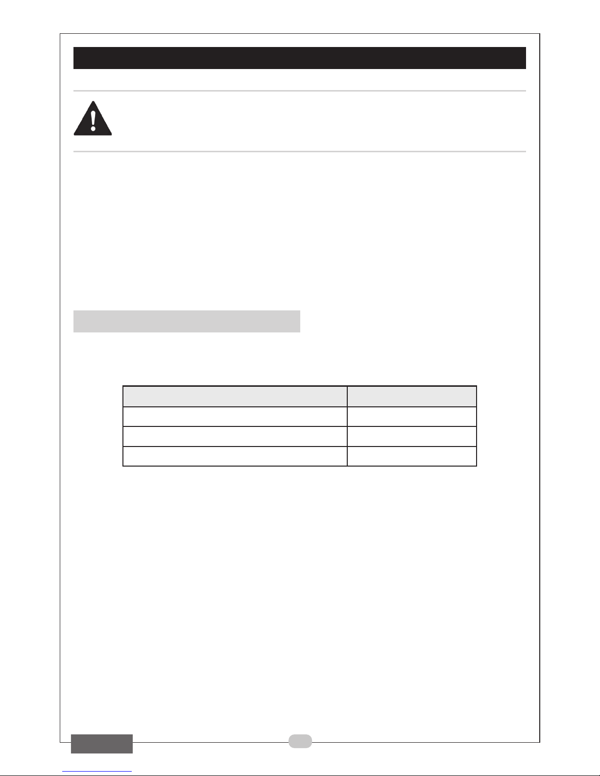
epyT rebmuNtraP
)kp5(sedalbgnittuclateM9202646
)kp5(sedalbgnittucdooW8202646
)kp5(sedalbgnittucgoL7202646
Page 11

11
PARTS & SERVICE
For Spare Parts and Service, please contact your nearest dealer, or CLARKE International,
on one of the following numbers.
PARTS & SERVICE TEL: 020 8988 7400
or e-mail as follows:
PARTS: [email protected]
SERVICE: [email protected]
PARTS DIAGRAM
Page 12
12
PARTS LIST
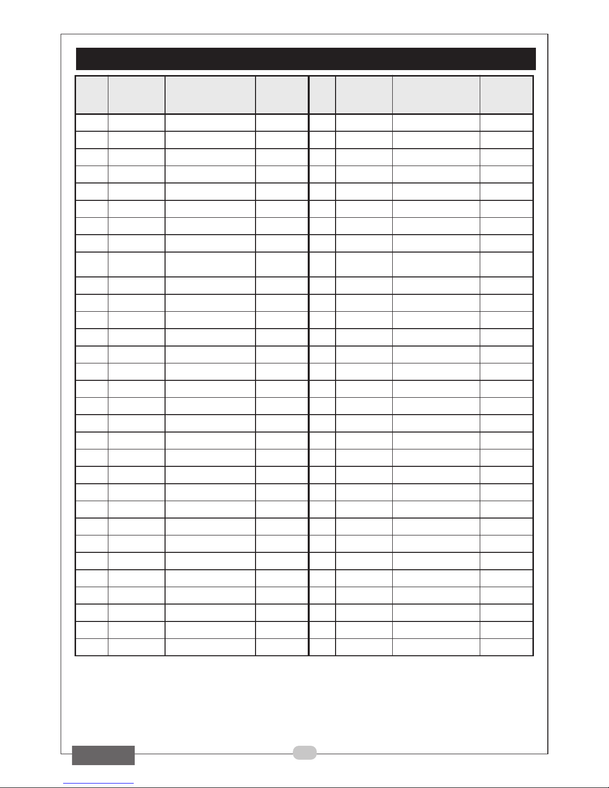
metI
traP
rebmuN
noitpircseD
elbaliavA
erapSasa
trap
metI
traP
rebmuN
noitpircseD
elbaliavA
erapSasa
trap
110001NOCPKwercSgnippaTseY2323001NOCPKwercSseY
220001NOCPKrehsaWgnirpSseY3333001NOCPKrehsaWseY
330001NOCPKwercSseY4343001NOCPKwercSdaeHtekcoSseY
440001NOCPKylbmessAetalPevoCseY5353001NOCPKniPgnisilacoLseY
550001NOCPKwercSpmalCedalBseY6363001NOCPKrotceleSmuludnePseY
660001NOCPKetalPpmalCedalBseY7373001NOCPKelbmihTseY
770001NOCPKgnihsurBreppoCseY8383001NOCPKgnirpSseY
880001NOCPKtfahSseY9393001NOCPKniPcitselEseY
990001NOCPKniPcitsalEseY0404001NOCPK
noitcucudeRdeepS
xobraeG
seY
0101001NOCPKniPcitsalEseY1414001NOCPKetalPgnitcennoCseY
1111001NOCPKkcabgnortSseY2424001NOCPKhctiwSseY
2121001NOCPKtekcarBseY3434001NOCPKgnirpSseY
3131001NOCPKgnirpSseY4444001NOCPKhctiwSseY
4141001NOCPKredloHwaSseY5454001NOCPKerusolcnEtfeLseY
5151001NOCPKredloHtfahSseY6464001NOCPKetalPtiucriCseY
6161001NOCPKeveelSrecapSseY7474001NOCPKhctiwSlrtCpotSkciuQseY
7171001NOCPKgniraeBrelloReldeeNseY8484001NOCPKlanimreTgniriWseY
8181001NOCPKleehWoryGseY9494001NOCPKroticapaCseY
9191001NOCPKniPseY0505001NOCPKrotatSseY
0202001NOCPKgniraeGseY1515001NOCPKgniraeBseY
1212001NOCPKrehsaWseY2525001NOCPKgniraeBhsurBseY
2222001NOCPKkcolBecnalaBseY3535001NOCPKhsurBnobraCseY
3232001NOCPKetalPefinkgnitfiLseY4545001NOCPKredloHhsurBseY
4242001NOCPKrehsaWseY5555001NOCPKrotoRseY
5252001NOCPKkcolBediuGseY6565001NOCPKgniraeBseY
6262001NOCPKrehsaWseY7575001NOCPKeveelSdroCseY
7272001NOCPKgniRgnixiFseY8585001NOCPKgulP+droCCAseY
8282001NOCPKteviRseY9595001NOCPKfeileRniartSseY
9292001NOCPKetalPgnitcennoCseY0606001NOCPKwercSgnippaTseY
0303001NOCPKeohSseY1616001NOCPKerusolcnEthgiRseY
1313001NOCPKedalBwaSseY
Page 13
13
VIBRATION EMISSIONS
Declared vibration emission value in accordance with EN12096
Measured vibration emission value -
a:
13.90 m/s
2
Uncertainty value -
K:
1.5 m/s
2
Highest measured reading in a single plane 26 m/s
2
Values determined according to EN28622-1
Employers are advised to refer to the HSE publication “Guide for Employers”.
All hand held power tools vibrate to some extent, and this vibration is
transmitted to the operator via the handle, or hand used to steady the tool.
Vibration from about 2 to 1500 hertz is potentially damaging and is most
hazardous in the range from about 5 to 20 hertz.
Operators who are regularly exposed to vibration may suffer from Hand Arm
Vibration Syndrome (HAVS), which includes ‘dead hand’, ‘dead finger’, and
‘white finger’. These are painful conditions and are widespread in industries
where vibrating tools are used.
The health risk depends upon the vibration level and the length of time of
exposure to it……in effect, a daily vibration dose.
Tools are tested using specialised equipment, to approximate the vibration
level generated under normal, acceptable operating conditions for the tool in
question. For example, a grinder used at 45° on mild steel plate, or a sander
on softwood in a horizontal plane etc.
These tests produce a value ‘a
’
,
expressed in metres per second per
second, which represents the average
vibration level of all tests taken, in three
axes where necessary, and a second
figure ‘K’, which represents the
uncertainty factor, i.e. a value in excess
of ‘a’, to which the tool could vibrate
under normal conditions.
These values appear in the specification
panel below.
HAND-ARM VIBRATION
Page 14

14
You will note that a third value is given in the specification - the highest
measured reading in a single plane. This is the maximum level of vibration
measured during testing in one of the axes, and this should also be taken into
account when making a risk assessment.
‘
a
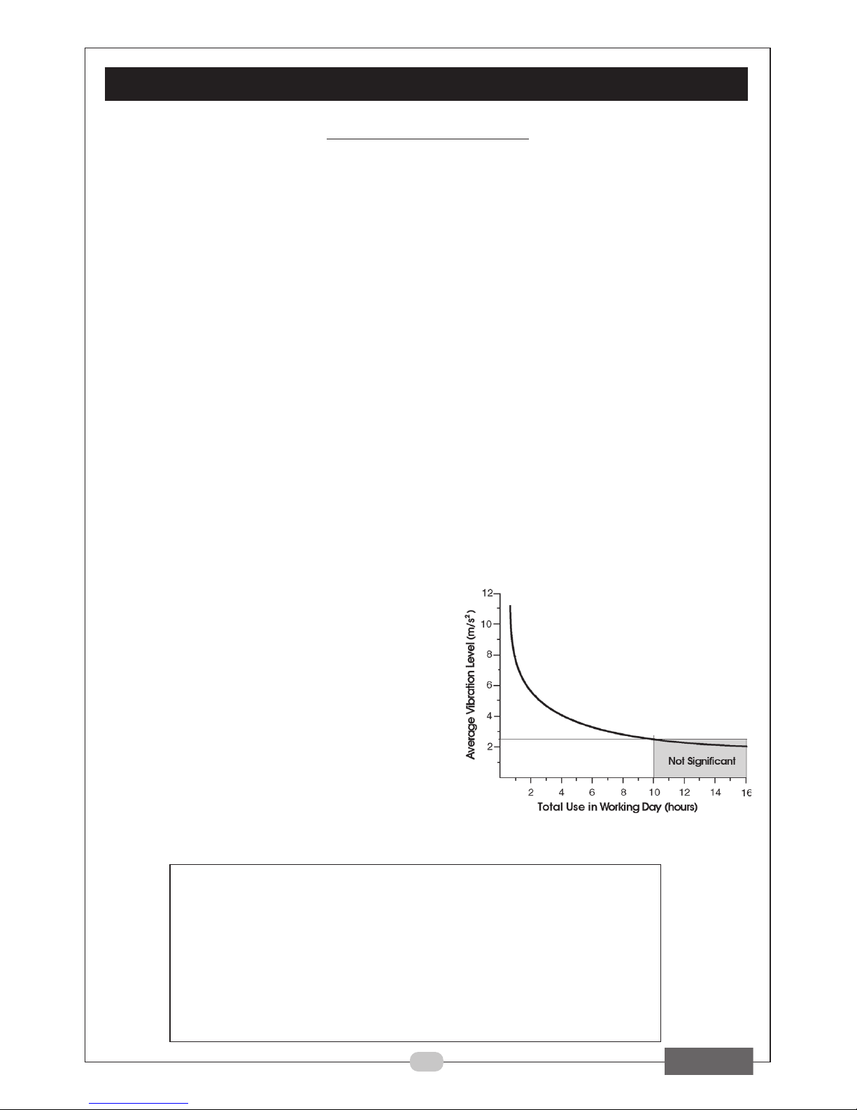
’ values in excess of 2.5 m/s2 are considered hazardous when used for
prolonged periods. A tool with a vibration value of 2.8 m/s2 may be used for
up to 8 hours (cumulative) per day, whereas a tool with a value of 11.2 m/s
2
may be used for ½ hour per day only.
The graph shows the vibration value against the maximum time the respective
tool may be used, per day.
The uncertainty factor should also be taken into account when assessing a risk.
The two figures ‘
a
’ and ‘
K’ may
be added together and the resultant value
used to assess the risk.
It should be noted that if a tool is used under abnormal, or unusual conditions,
then the vibration level could possibly increase significantly. Users must always
take this into account and make their own risk assessment, using the graph on
the opposite page as a reference.
Some tools with a high vibration value, such as impact wrenches, are
generally used for a few seconds at a time, therefore the cumulative time may
only be in the order of a few minutes per day. Nevertheless, the cumulative
effect, particularly when added to that of other hand held power tools that
may be used, must always be taken into account when the total daily dose
rate is determined.
VIBRATION EMISSIONS
Page 15

15
DECLARATION OF CONFORMITY
When disposing of this product, ensure it is disposed of according to all
local ordinances. It must not be disposed of with general household
waste.
Page 16

 Loading...