

Page 1
OPERATING & MAINTENANCE
INSTRUCTIONS
Model No. CON1200
PART NO: 6479505
GC0611
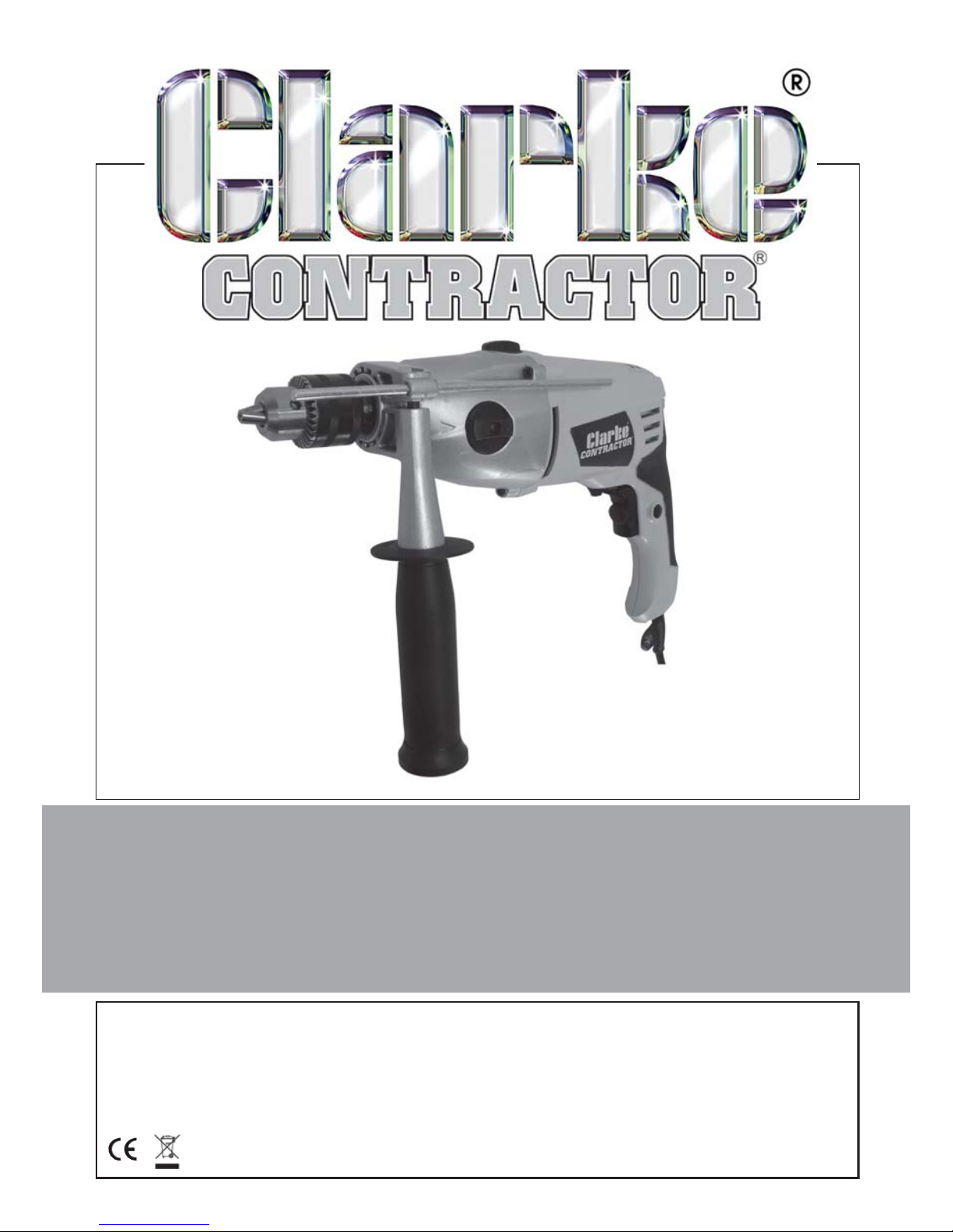
1200W HAMMER DRILL
Page 2
2
Parts & Service: 020 8988 7400/E-mail:[email protected] or [email protected]
INTRODUCTION
Thank you for purchasing this CLARKE Hammer Drill.
Before attempting to use the machine, please read this manual thoroughly
and follow the instructions carefully. In doing so you will ensure the safety of
yourself and that of others around you, and you can look forward to your
purchase giving you long and satisfactory service.
GUARANTEE
This product is guaranteed against faulty manufacture for a period of 12
months from the date of purchase. Please keep your receipt which will be
required as proof of purchase.
This guarantee is invalid if the product is found to have been abused or
tampered with in any way, or not used for the purpose for which it was
intended.
Faulty goods should be returned to their place of purchase, no product can
be returned to us without prior permission.
This guarantee does not effect your statutory rights.
ENVIRONMENTAL PROTECTION
Do not dispose of this product with general household waste. It must be
disposed of according to the laws governing Waste Electrical and
Electronic Equipment at a recognised disposal facility.
Page 3

3
Parts & Service: 020 8988 7400/E-mail:[email protected] or [email protected]
TABLE OF CONTENTS
INTRODUCTION .................................................................................. 2
GUARANTEE ........................................................................................ 2
ENVIRONMENTAL PROTECTION .........................................................2
TABLE OF CONTENTS .......................................................................... 3
GENERAL SAFETY RULES ..................................................................... 4
HAMMER DRILL SAFETY INSTRUCTIONS .............................................6
ELECTRICAL CONNECTIONS .............................................................. 7
OVERVIEW ..........................................................................................8
OPERATION .........................................................................................9
MAINTENANCE ...................................................................................11
FAULT FINDING ................................................................................... 12
ACCESSORIES & CONSUMABLE SPARES ............................................ 12
SPECIFICATION ...................................................................................13
SPARE PARTS .......................................................................................14
VIBRATION EMISSIONS ....................................................................... 17
DECLARATION OF CONFORMITY .......................................................19
Page 4

4
Parts & Service: 020 8988 7400/E-mail:[email protected] or [email protected]
GENERAL SAFETY RULES
WORK AREA
1. Keep the work area clean and well lit. Cluttered and dark areas invite
accidents.
2. Do not operate power tools in explosive atmospheres such as in the
presence of flammable liquids, gasses or dust. Power tools create sparks
which may ignite dust or fumes.
3. Keep children and bystanders away while operating a power tool.
Distractions can cause you to lose control.
ELECTRICAL SAFETY
1. Power tools must match the power outlet. Never modify the plug in any
way. Do not use adaptor plugs with earthed (grounded) power tools.
Correct plugs and outlets will reduce the risk of electric shock.
2. Do not expose power tools to rain or wet conditions. Any water entering
power tools will increase the risk of electric shock.
3. Do not abuse the electrical cable. Never use the cord for pulling or un-
plugging the power tool. Keep the cable away from sources of heat, oil,
sharp edges or moving parts. Damaged or tangled cables increase the
risk of electric shock.
4. When operating a power tool outdoors, use an extension cable suitable
for outdoor use. Using the correct cable reduces the risk of electric shock.
PERSONAL SAFETY
1. Stay alert, watch what you are doing and use common sense when you
are operating a power tool. Do not operate a power tool when you are
tired, ill or under the influence of alcohol, drugs or medication.
2. Wear personal protective equipment including eye protection. Safety
equipment such as a dust mask, non-skid shoes or hearing protection used
for appropriate conditions will reduce personal injuries. Use a face or dust
mask if operation is particularly dusty. Wear ear protectors/defenders as
the noise level of this machine can exceed 85dB (A).
3. Do not over-reach. Keep your proper footing and balance at all times. This
enables better control of the power tool in unexpected situations.
4. Avoid accidental starting of the machine. Ensure the switch is in the off
position and the trigger lock button disengaged before plugging the
machine in to the power supply. Carrying power tools around with your
finger on the trigger or plugging in power tools that are switched on invites
accidents.
Page 5

5
Parts & Service: 020 8988 7400/E-mail:[email protected] or [email protected]
5. Dress properly. Do not wear loose clothing or jewellery which may get
caught in moving parts. Wear protective hair covering to contain long
hair. For best footing, wear rubber soled footwear. Keep floor clear of oil,
scrap wood, etc.
6. Concentrate on the job in hand, no matter how trivial it may seem. Be
aware that accidents are caused by carelessness due to familiarity.
7. Switch the machine OFF immediately after the task is completed.
POWER TOOL USE AND CARE
1. Do not force the machine. Use the correct power tool for your application.
It will do a better and safer job at the rate for which it was designed.
2. Do not use the power tool if the trigger does not turn it on and off. Any
power tool that cannot be controlled with the switch is dangerous and
must be repaired.
3. Disconnect the power tool from the power supply before making any
adjustments, changing accessories, or storing the tool. These measures will
reduce the risk of the power tool starting accidentally.
4. Store power tools out of the reach of children and do not allow persons
unfamiliar with these instructions to operate the power tool. Power tools
are potentially dangerous in the hands of untrained users.
5. Maintain power tools in top condition. Keep tools/ machines clean for the
best and safest performance. Check for misalignment or binding of
moving parts, broken parts, or any condition that may affect the power
tool’s operation. If damaged, have the power tool repaired before use.
Many accidents are caused by poorly maintained power tools.
6. Use recommended accessories. The use of improper accessories could be
hazardous.
7. Machine cleanliness. Do not allow the ventilation slots in the machine to
become blocked with dust.
8. Check the power tool for damage before using the machine. Any
damaged part should be inspected to ensure that it will operate properly
and perform its intended function. Check for alignment of moving parts,
breakage of parts, mountings, and any other condition that may affect
the machines operation. Any damage should be properly repaired or the
part replaced. If in doubt, DO NOT use the machine. Consult your local
dealer.
SERVICE
1. When necessary, have your power tools serviced or repaired by a
qualified person using identical replacement parts. This will ensure that the
safety of the power tool is maintained.
Page 6

6
Parts & Service: 020 8988 7400/E-mail:[email protected] or [email protected]
HAMMER DRILL SAFETY INSTRUCTIONS
1. Only use the hammer drill in the manner and for the functions described in
these instructions.
2. Using the correct bit. Use the appropriate drill bit for the material being
drilled. Different bits are available from your Clarke dealer.
3. Use of the mains cable. Keep the mains cable well away from the drill and
ensure an adequate electrical supply is close at hand so that the
operation is not restricted by the length of the cable.
4. Working on the bench. Allow sufficient clearance beneath the work to
ensure the drill bit does not come into contact with the floor, table etc.
5. Switching off. Never place the drill on a table or bench if it has not
completely stopped. The drill bit will continue to rotate for a short time
after the trigger has been released to stop the drill.
6. Drilling into walls. Do not drill into walls or cavities before checking for
hidden electrical wires or water pipes etc.
7. Finishing drilling. Do not touch the drill bit immediately after use. Allow
time for it to cool.
8. Use outdoor extension leads. If working outdoors, always use an approved
cable extension suitable for the power rating of this tool (see
specifications), the conductor size should also be at least the same size as
that on the machine, or larger. When using a cable reel, always unwind
the cable completely. We strongly recommend that this machine is
connected to the mains supply via a Residual Current Device (RCD).
9. Cooling agents. When drilling metals, always use a cooling agent i.e.
cutting/soluble oil.
Additionally, please keep these instructions in a safe place for future reference.
Page 7
7
Parts & Service: 020 8988 7400/E-mail:[email protected] or [email protected]
ELECTRICAL CONNECTIONS
WARNING! Read these electrical safety instructions thoroughly
before connecting the product to the mains supply.
Before switching the product on, make sure that the voltage of your electricity supply is the same as that indicated on the rating plate. This product is
designed to operate on 230VAC 50Hz. Do not connect it to any other power
source.
This product may be fitted with a non-rewireable plug. If it is necessary to
change the fuse in the plug, the fuse cover must be refitted. If the fuse cover
becomes lost or damaged, the plug must not be used until a suitable replacement is obtained.
If the plug has to be changed because it is not suitable for your socket, or
due to damage, it should be cut off and a replacement fitted, following the
wiring instructions shown below. The old plug must be disposed of safely, as
insertion into a mains socket could cause an electrical hazard.
WARNING! The wires in the power cable of this product are
coloured in accordance with the following code:
Blue = Neutral Brown = Live
If the colours of the wires in the power cable of this product do not correspond with the terminal markings of your plug, proceed as follows.
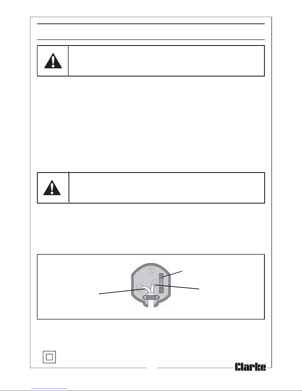
• The wire which is coloured Blue must be connected to the terminal which
is marked N or coloured Black.
• The wire which is coloured Brown must be connected to the terminal
which is marked L or coloured Red.
Plug must be BS1363/A approved.
Always fit a 13 Amp fuse.
Neutral Live
(Blue) (Brown)
Ensure that the outer sheath of the cable is firmly held by the clamp
We strongly recommend that this product is connected to the mains supply
via a Residual Current Device (RCD).
If in doubt, consult a qualified electrician. DO NOT attempt repairs yourself.
This symbol indicates that this is a Class II product and does not require
an earth connection.
Page 8
8
Parts & Service: 020 8988 7400/E-mail:[email protected] or [email protected]
OVERVIEW
The CLARKE CON1200 is a variable-speed drill, equipped with an adjustable
speed controller, high and low gear selection and hammer operation and
has a lock-on button for continuous operation. The drill is supplied with a
depth stop rod and auxiliary handle.
When unpacking, check for damage or shortages etc. Any found should be
reported to your CLARKE dealer where the appliance was originally
purchased. This CON1200 Drill is supplied with the following components:
• 1 x Chuck Key
• 1 x Depth Stop Rod
• 1 x Auxiliary (Side) Handle
• 1 x Instruction Manual (this document)
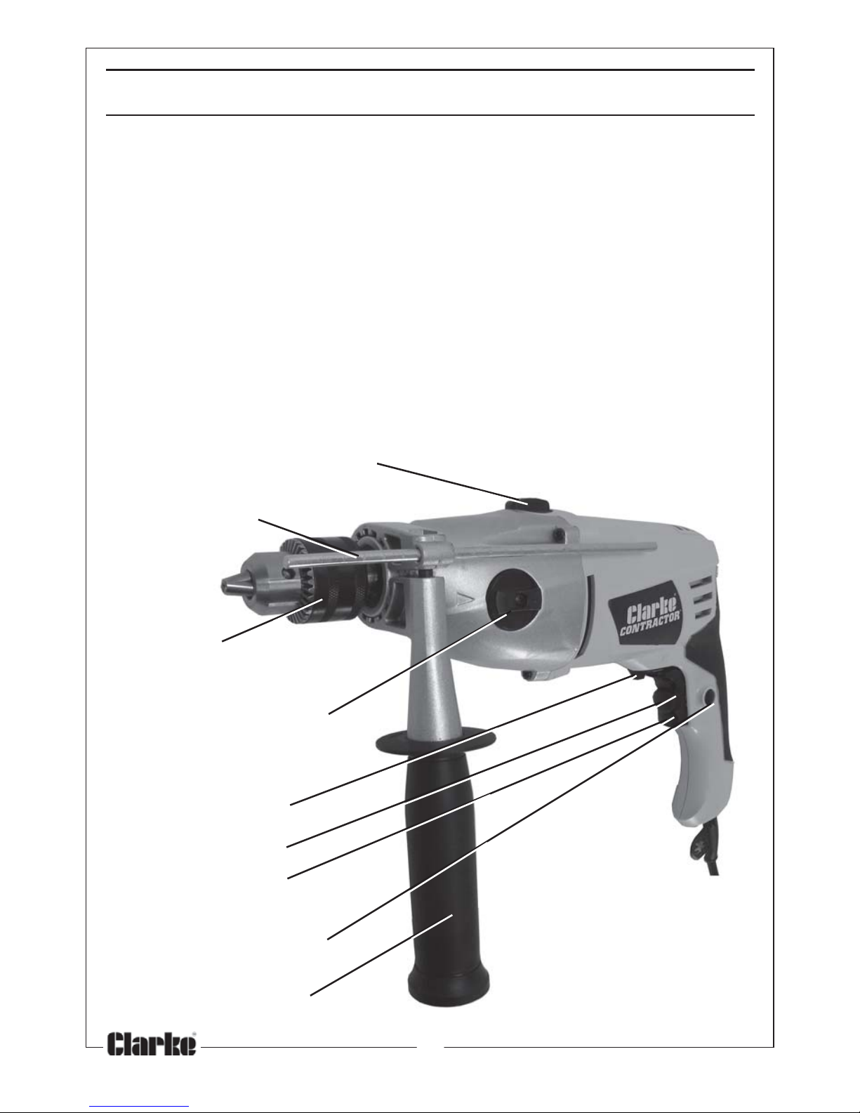
Drill/Hammer Drill Selector
Depth Stop
Chuck
Gear Selector Knob
Selector Switch
Speed Control
Trigger
Trigger Lock-on Button
Auxiliary Handle
Forward/Reverse
Page 9
9
Parts & Service: 020 8988 7400/E-mail:[email protected] or [email protected]
OPERATION
IMPORTANT: To avoid accidental starting, ensure the drill is switched OFF
before plugging in to the mains. To do this, briefly pull the switch, and release
to ensure the trigger lock is not set in the ‘lock’ position.
INSERTING A DRILL BIT
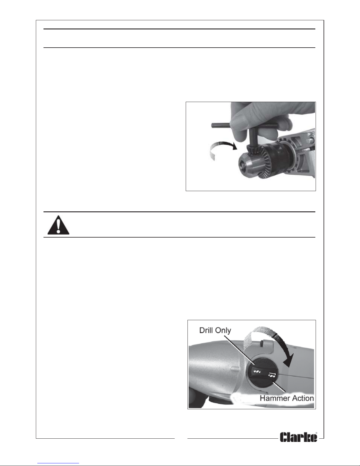
1. Open the chuck by rotating the
chuck sleeve anticlockwise until
the jaws are open sufficiently to
take the drill bit.
2. Place the drill bit in the jaws of the
chuck as far as it will go.
3. Insert the chuck key in one of the
three holes in the chuck and
tighten in a clockwise direction.
• Make sure the head of the chuck
key is firmly located on the cog
barrel of the chuck when tightening.
REMOVE THE CHUCK KEY BEFORE OPERATING THE DRILL.
• To remove the bit, release by inserting the chuck key in one of the holes
and turning in an anticlockwise direction.
SWITCHING ON & CONTINUOUS OPERATION
1. Plug into a 13 amp socket and squeeze the trigger to start the drill.
2. During use, press the trigger lock-on button & the drill will run continuously.
Squeeze the trigger again briefly to release the trigger lock & stop the drill.
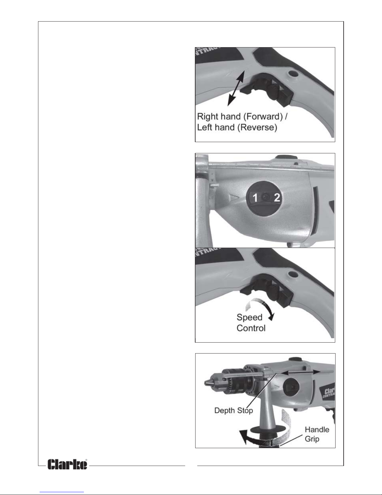
HAMMER DRILL SELECTION
Rotate the ‘Drill/Hammer Drill’ mode
selection switch so that the ‘Hammer’
symbol is aligned with the raised mark
on the drill body.
NORMAL DRILL SELECTION
Rotate the drill/hammer drill mode
selection switch so that the ‘Drill’
symbol is aligned with the raised mark
on the drill body.
NOTE: Both these operations should only be performed when the drill is at a
complete stop.
Page 10
10
Parts & Service: 020 8988 7400/E-mail:[email protected] or [email protected]
FORWARD / REVERSE SELECTION
1. Set the forward/reverse selector
switch to the position marked ‘R’
for normal ‘Right hand’ rotation.
2. Set the forward/reverse selector
switch to the right hand position
marked ‘L’ for ‘Left hand’ rotation.
NOTE: This should only be performed
when the drill is at a complete stop.
SPEED SELECTION
1. Set the high or low speed by
selecting one of the two gear
speeds (1-low or 2-high) with the
selector.
• Turn the speed selector knob until
the chosen number is aligned with
the arrow on the drill body).
NOTE: This should only be performed
when the drill is at a complete stop.
• Variable speeds may be selected
by turning the speed control in the
centre of the trigger.
AUXILIARY HANDLE & DEPTH STOP
1. Fit the depth stop along with the
auxiliary handle.
• This can only be used if the handle
is installed.
2. Slide the handle assembly over the
chuck and onto the body of the
drill. Insert the depth stop rod into
the holder in the handle assembly,
rotate the handle to the desired
position and secure in position by
twisting the handle grip clockwise,
DO NOT overtighten.
• To set the depth stop, loosen the
handle by turning the handle grip
anticlockwise and slide the rod or
and out to the required position.
• The scale markings on the rod are
for reference only.
Page 11

11
Parts & Service: 020 8988 7400/E-mail:[email protected] or [email protected]
GENERAL DRILLING TECHNIQUE
• After drilling material to the full depth, maintain chuck rotation to ease drill
withdrawal.
• Keep drill bits sharpened for optimum performance.
• Always drill directly in line with the bit. Do not use sideways movement as
this may damage the drill or cause the bit to break.
• Always use a cutting lubricant when drilling metals except for brass and
cast iron which should be drilled dry.
• If the drill is not cutting the metal then sharpen the drill bits, ensuring the
various cutting angles are correct.
MAINTENANCE
Before commencing any maintenance procedures, always ensure the drill is
isolated from the electrical supply by switching off and removing the plug
from the socket.
BEFORE USE
1. Ensure all fixing screws remain tight to ensure the drill is in safe working
condition.
2. Inspect the power cable to ensure it is sound and free from cracks, bare
wires etc.
CLEANING
1. Ensure all air ventilation slots are clear of blockages, (use compressed air
to clean the machine if possible).
2. After use, clean all dust and swarf from the drill.
3. Clean the exterior of the drill with a soft cleaning cloth. Never use any
chemicals or harsh abrasives to clean the tool.
• Avoid using solvents when cleaning plastic parts, most plastics are
susceptible to damage from the various types of commercial solvents.
GENERAL MAINTENANCE
• All bearings etc, in this tool are lubricated with a sufficient amount
of high grade lubricant for the tools lifetime under normal
operating conditions, therefore no further lubrication is necessary.
• Refer to your CLARKE dealer if internal maintenance is required.
Page 12
12
Parts & Service: 020 8988 7400/E-mail:[email protected] or [email protected]
FAULT FINDING
melborP esuaCelbissoP ydemeR
.etarepotonlliwlooT.ylppusrewopoNsayfitcerdnaylppuskcehC
.yrassecen
.ytluafsihctiwS.relaedekralCruoy
tlusnoC
.nwolbesuFfiecalperdnakcehC
.yrassecen
.ytluafsirotoM.relaedekralCruoytlusnoC
tibllirdtubsnurrotoM
.
evomtonseod
.thgittongninetsafllirD.tibllirderuceS
.nekorbraegevirD.relaedekralCruoytlusnoC
lanretniyvaeH
.
gnikraps
.rotomytluaF.relaedekralCruoytlusnoC
.sehsurBnroW.relaedekralCruoytlusnoC
.tohsemocebrotoM.esuyvae
hyludnUotdeilppaecrofehtecudeR
ehtodlootehtteL.looteht
.krow
emocebevahstnevriA
.dekcolb
gnisustnevriaehttu
onaelC
ahtiwnaelcroriadesserpmoc
.htolcyrd
.egatlovylppuswoLsiegatlovylppuserusnE
sielbacnoisnetxenafI.tce
rroc
tcerrocehtfositierusne,desu
.dnuownuyllufsidnagnitar
.noitarbivevissecxEtonrotnebtibllirD
.yltcerrocd
etnuom
.yfitcerdnakcehC
.nrowsgniraebenihcaM.relaedekralCruoytlusnoC
ACCESSORIES & CONSUMABLE SPARES
An extensive selection of accessories including Drill Bit Sets, Socket & Bit Sets
and Drill Bit Sharpeners are available from your CLARKE dealer. Refer to your
Clarke dealer or service department if internal maintenance is required.
Page 13
13
Parts & Service: 020 8988 7400/E-mail:[email protected] or [email protected]
metI noitacificepS
sedoMgnitarepO remmaH&llirD/llirD
yticapaCkcuhCmm31-5.1
)raeGhgiH/raeGwoL(sdeepSdaoLoNdetaRmp
r0082-0/0001-0
thgieWgk2.3
)HxWxL(snoisnemiDmm532x88x073
ycneuqerF&egatloVgnitarepOzH05/V032
gnitaResuFA31
rew
oProtoMW0021
)eldnahraer/tnorf(noitarbiVm686.61/151.8
2
levelerusserPdnuoSAWLBd7.59
rewoPdnuoSdeetnarauGAWLBd7.601
SPECIFICATIONS
Please note that the details and specifications contained herein, are correct
at the time of going to print. However, CLARKE International reserve the right
to change specifications at any time without prior notice.
Page 14
Page 15
15
Parts & Service: 020 8988 7400/E-mail:[email protected] or [email protected]
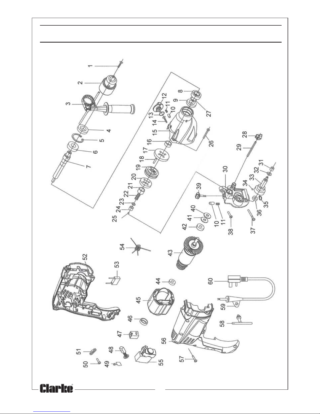
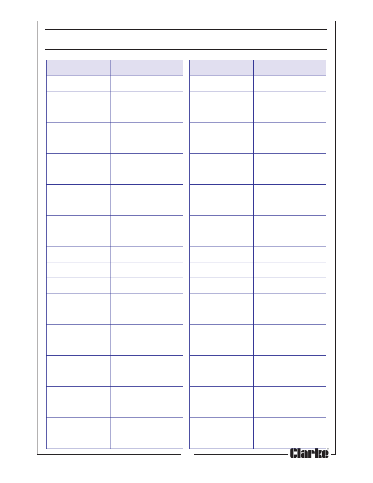
oN oNtraP noitpircseD oN oNtraP noitpircseD
110021DHCGWwercSniateRkcuhC5252021DHCGWllaBleetS
220021DHCGWkcuhC6262021DHCGWwercSgnippat-fleS
330021DH
CGWeldnaHediS7272021DHCGWpilcriC
440021DHCGWlaeSliO8282021DHCGWeceiPegnahCraeG
550021DHCGWpilcriC9292021DHCGWniP
660021
DHCGW2006gniraeB0303021DHCGWgnisuoHtcapmI
770021DHCGWeldnipSkcuhC1313021DHCGW8060KHgrBeldeeN
880021DHCGWkcolBtcapm
IreppU2323021DHCGWrehsaW
990021DHCGWkcolBtcapmIrewoL3333021DHCGWraeGeldnipS
0101021DHCGWdaeHtelluB4343021DHCGWllaBle
etS
1111021DHCGWgnirpStcapmI5353021DHCGWpilcriC
2121021DHCGWrotceleSraeG6363021DHCGWZ696gniraeB
3131021DHCGWgniR-O7373
021DHCGWwercS
4141021DHCGWwercSgnippat-fleS8383021DHCGWwercS
5151021DHCGWgnisuoHtnorF9393021DHCGWrotceleStcapmI
6161
021DHCGWeveelSleetStnorF0404021DHCGWlaeSliO
7171021DHCGWraeGegraL1414021DHCGWdaPtleF
8181021DHCGWniP2424021DHCGW806gn
iraeB
9191021DHCGWkcolBegnahCraeG3434021DHCGWerutamrArotoM
0202021DHCGWraeGllamS4444021DHCGW706gniraeB
1212021DHCGWe
veelSleetSraeR5454021DHCGWrotatSrotoM
2222021DHCGWgnirpS6464021DHCGWrevoCgniraeB
3232021DHCGWrehsaW7474021DHCGWredlo
HhsurB
4242021DHCGW9070KHgrBeldeeN8484021DHCGWhsurB
PARTS LIST
Page 16
16
Parts & Service: 020 8988 7400/E-mail:[email protected] or [email protected]
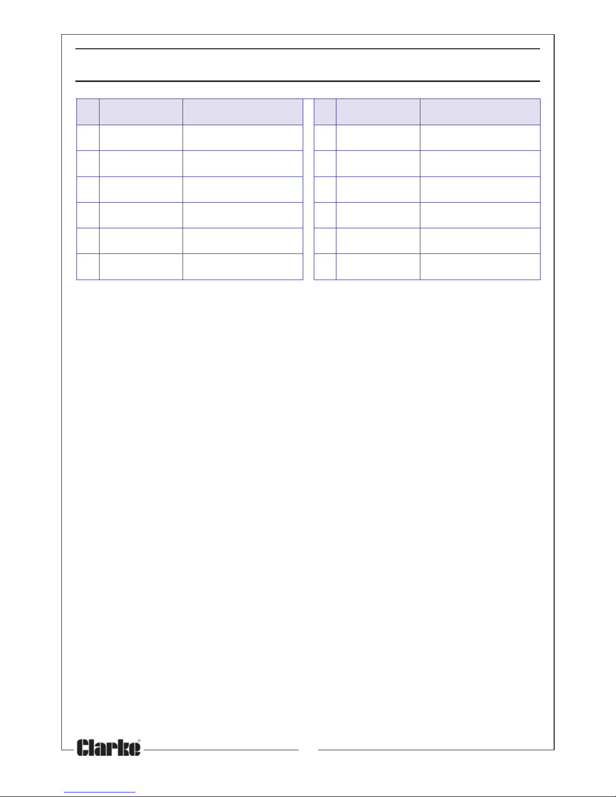
oN oNtraP noitpircseD oN oNtraP noitpircseD
9494021DHCGWpilChsurB5555021DHCGWylbmessAreggirT
0505021DHCGWwercSpmalC6565021DHCGW)HR(gnisaC
1515021DHCGWpmalCelbaC7575021DHCGWwercS
2525021DHCGW)HL(gnisaC8585021DHCGWyeKkcuhC
3535021DHCGWroticapaC9595021DHCGWdaeLrewoP
4
545021DHCGWrotcudnI0606021DHCGWgulPrewoP
PARTS LIST
Page 17

17
Parts & Service: 020 8988 7400/E-mail:[email protected] or [email protected]
VIBRATION EMISSIONS
MODEL No: CON1200
DESCRIPTION: 1200W HAMMER DRILL
Declared vibration emission value in accordance
with EN12096
Measured vibration emission value - a: 16.7m/s
2
Uncertainty value - K: 1.5m/s
2
Values determined according to EN28622-1
Employers are advised to refer to the HSE publication “Guide for Employers”.
All hand held power tools vibrate to some extent, and this vibration is
transmitted to the operator via the handle, or hand used to steady the tool.
Vibration from about 2 to 1500 Hertz is potentially damaging and is most
hazardous in the range from about 5 to 20 Hertz.
Operators who are regularly exposed to vibration may suffer from Hand Arm
Vibration Syndrome (HAVS), which includes ‘dead hand’, ‘dead finger’, and
‘white finger’. These are painful conditions and are widespread in industries
where vibrating tools are used.
The health risk depends upon the vibration level and the length of time of
exposure to it……in effect, a daily vibration dose.
Tools are tested using specialised equipment, to approximate the vibration
level generated under normal, acceptable operating conditions for the tool
in question. For example, a grinder used at 45° on mild steel plate, or a
sander on softwood in a horizontal plane etc.
These tests produce a value ‘a’, expressed in metres per second per second,
which represents the average vibration level of all tests taken, in three axes
where necessary, and a second figure ‘K’, which represents the uncertainty
factor, i.e. a value in excess of ‘a’, to which the tool could vibrate under
normal conditions. These values appear in the specification panel below.
HAND-ARM VIBRATION
Page 18
18
Parts & Service: 020 8988 7400/E-mail:[email protected] or [email protected]
You will note that a third value is given in the specification - the highest
measured reading in a single plane. This is the maximum level of vibration
measured during testing in one of the axes, and this should also be taken into
account when making a risk assessment.
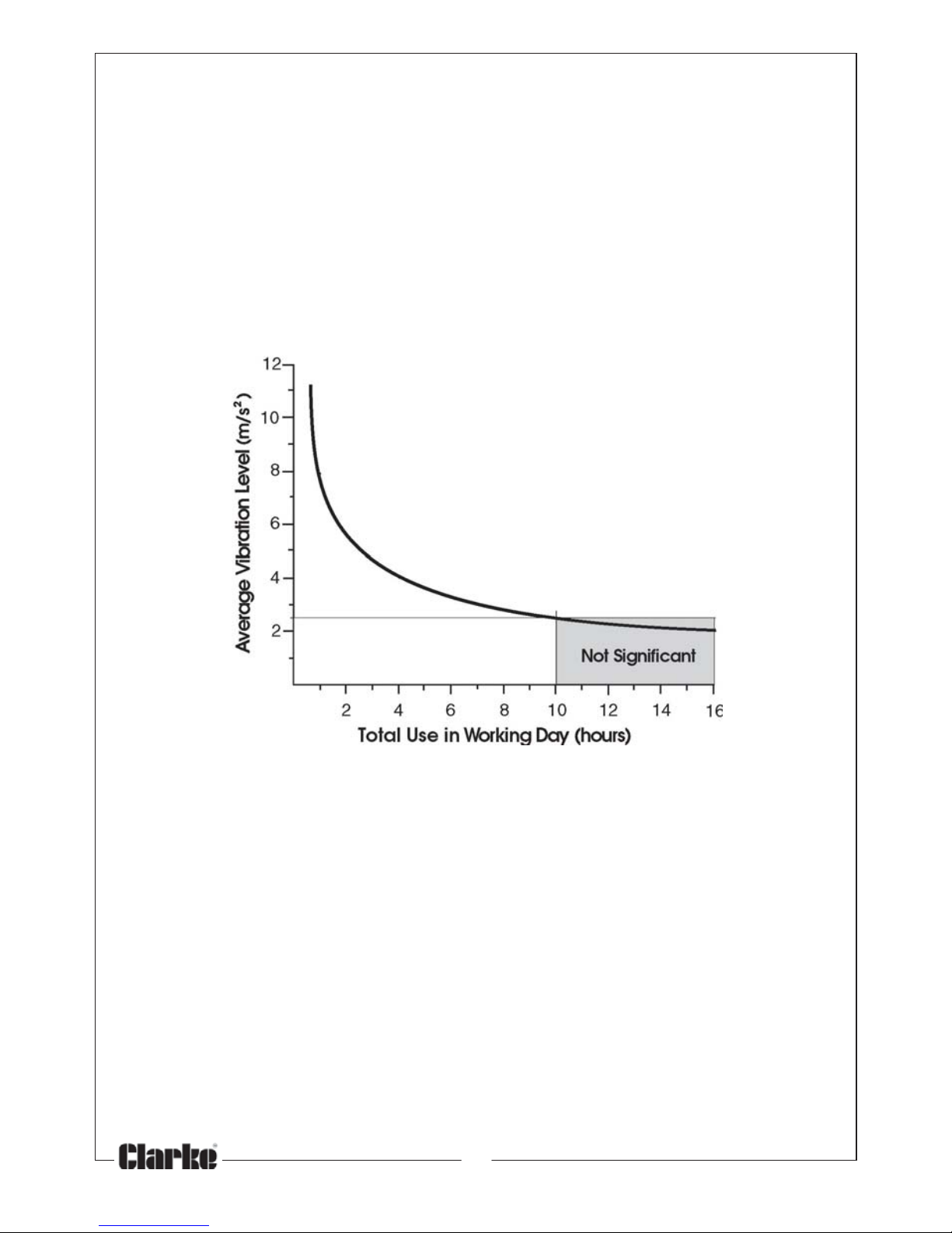
‘a’ values in excess of 2.5 m/s
2
are considered hazardous when used for
prolonged periods. A tool with a vibration value of 2.8 m/s2 may be used for
up to 8 hours (cumulative) per day, whereas a tool with a value of 11.2 m/s
2
may be used for ½ hour per day only.
The graph below shows the vibration value against the maximum time the
respective tool may be used, per day.
The uncertainty factor should also be taken into account when assessing a
risk. The two figures ‘a’ and ‘K’ may be added together and the resultant
value used to assess the risk.
It should be noted that if a tool is used under abnormal, or unusual conditions,
then the vibration level could possibly increase significantly. Users must
always take this into account and make their own risk assessment, using the
graph above as a reference.
Some tools with a high vibration value, such as impact wrenches, are
generally used for a few seconds at a time, therefore the cumulative time
may only be in the order of a few minutes per day. Nevertheless, the
cumulative effect, particularly when added to that of other hand held power
tools that may be used, must always be taken into account when the total
daily dose rate is determined.
Page 19
19
Parts & Service: 020 8988 7400/E-mail:[email protected] or [email protected]
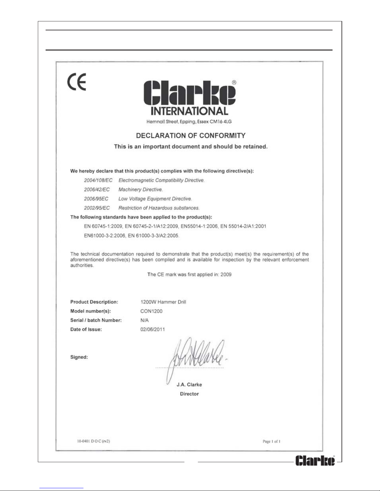
DECLARATION OF CONFORMITY
Page 20
 Loading...