

Page 1

VARIABLE SPEED
JIG SAW
DEMOLITION HAMMER
DEMOLITION HAMMER
MODEL No. CON2100 / CON2300
OPERATING & MAINTENANCE
Part No. 6460200
Part No. 6462076 / 6462078
INSTRUCTIONS
LS0209
Page 2

Thank you for purchasing this CLARKE demolition hammer.
Before attempting to use the demolition hammer please read this manual
thoroughly and follow the instructions carefully. In doing so you will ensure the
safety of yourself and that of others around you, and you can look forward to
the demolition hammer giving you long and satisfactory service.
GUARANTEE
This product is guaranteed against faulty manufacture for a period of 12 months
from the date of purchase. Please keep your receipt which will be required as
proof of purchase.
This guarantee is invalid if the product is found to have been abused or tampered
with in any way, or not used for the purpose for which it was intended.
Faulty goods should be returned to their place of purchase, no product can be
returned to us without prior permission.
This guarantee does not effect your statutory rights.
SPECIFICATIONS
ledoM0012NOC0032NOC
rebmuNtraP67026468702646
egatloVzH05@V011zH05@V032
rewoPW0012W0012
)nimrepsekorts(etartcapmI05
ygrenetcapmIseluoJ72-7seluoJ72-7
redloHlooTxeH12xeH12
etercnocniyticapaCmumixaMmm05mm05
oisnemiD052x031x547052x031x547
)HxWxL(sn
thgieWgk71gk71
derusaeMrewoPdnuoSwL)A(Bd201
)SMR(noitarbiVs/m79.9
91-0570591-057
A
2
wL)A(Bd201
A
2
s/m79.9
PACK CONTENTS
• Demolition hammer • Side handle
• 1 x Chisel • 1 x Drill bit
Please note that the details and specifications contained herein, are correct at the time of going to print.
However, CLARKE International reserve the right to change specifications at any time without prior notice.
2
Page 3

SAFETY PRECAUTIONS
WARNING!
As with all machinery, there are certain hazards involved with their
operation and use. Exercising respect and caution will considerably
lessen the risk of personal injury. However, if normal safety precautions
are overlooked or ignored, personal injury to the operator or damage
to property, may result.
1. ALWAYS Learn the machines applications, limitations and the specific
potential hazards peculiar to it. Read and become familiar with the entire
operating manual.
2. ALWAYS use a face or dust mask if the operation is particularly dusty.
3. ALWAYS check for damage. before using the machine, any damaged part,
should be checked to ensure that it will operate properly, and perform its
intended function. Check for alignment of moving parts, breakage of parts,
mountings, and any other condition that may affect the machines’
operation. Any damage should be properly repaired or the part replaced.
If in doubt, DO NOT use the machine. Consult your local dealer.
4. ALWAYS disconnect the tool/machine from the power supply before
servicing and when changing accessories.
5. ALWAYS wear safety goggles, manufactured to the latest European Safety
Standards. Everyday eyeglasses do not have impact resistant lenses, they
are not safety glasses.
6. ALWAYS keep work area clean. Cluttered areas and benches invite
accidents.
7. ALWAYS ensure that adequate lighting is available. A minimum intensity of
300 lux should be provided. Ensure that lighting is positioned so that you will
not be working in your own shadow.
8. ALWAYS keep children away. All visitors should be kept a safe distance from
the work area, especially whilst operating the machine.
9. ALWAYS maintain machine in top condition. Keep tools/machines clean for
the best and safest performance, follow maintenance instructions.
10. ALWAYS handle with extreme care do not carry the tool/machine by its’
electric cable, or yank the cable to disconnect it from the power supply .
11. ALWAYS ensure the switch is off before plugging in to mains. Avoid
accidental starting.
12. ALWAYS concentrate on the job in hand, no matter how trivial it may seem.
Be aware that accidents are often caused by carelessness due to
familiarity.
3
Page 4

13. ALWAYS keep your proper footing and balance at all times - don’t
overreach. For best footing, wear rubber soled footwear. Keep floor clear
of oil, scrap wood, etc.
14. ALWAYS wear proper apparel. Loose clothing or jewellery may get caught in
moving parts. Wear protective hair covering to contain long hair.
15. ALWAYS use recommended accessories. The use of improper accessories
could be hazardous.
16. ALWAYS remove plug from electrical outlet when adjusting, changing parts,
or working on the machine.
17. NEVER operate machine while under the influence of drugs, alcohol or
medication.
18. NEVER leave machine running unattended. Turn power off. Do not leave the
machine until it comes to a complete stop.
19. NEVER force the machine. It will do a better and safer job at the rate for
which it was designed.
20. NEVER use power tools in damp or wet locations or expose them to rain.
Keep your work area well illuminated. Do not use in explosive atmosphere
(around paint fumes, flammable liquids etc.). Avoid dangerous environment.
ADDITIONAL PRECAUTIONS FOR DEMOLITION HAMMER
1. Always wear ear protectors/defenders, as the noise level of this machine
can exceed 85dB (A).
2. In cold-weather conditions or when the tool has not been used for a longer
period of time, let the tool run with no load for several minutes before use.
3. Always hold the tool firmly with both hands and ensure a secure stance.
4. Always operate the tool with the side handle properly mounted.
5. When working above ground level ensure the area below is clear.
6. To prevent electric shock, check the working area for live wires before
operation.
7. Do not touch the bit/chisel or the parts close to the bit/chisel immediately
after operation, as they maybe extremely hot and cause burns to the skin.
8. Always direct the power cable to the rear, away from the tool.
9. Do not attempt any electrical repair yourself. Consult a qualified electrician,
or our Service Department on 020 8988 7400
Additionally, please keep these instructions in a safe place for future reference.
4
Page 5

ELECTRICAL CONNECTIONS
230 VOLT MODELS
Connect the mains lead to a standard, 230 Volt (50Hz) electrical supply through
an approved 13 amp BS 1363 plug, or a suitably fused isolator switch.
WARNING! THIS APPLIANCE MUST BE EARTHED
IMPORTANT: The wires in the mains lead are coloured in accordance with the
following code:
As the colours of the flexible lead of this appliance may not correspond with the
coloured markings identifying terminals in your plug, or your mains supply,
proceed as follows:
• No connection should be made to the plug terminal marked with a letter “E” or
Earth symbol “ ” or coloured GREEN or GREEN & YELLOW.
• Connect BROWN cord to terminal marked with a letter “L” or coloured RED.
• Connect BLUE cord to terminal marked with a letter “N” or coloured BLACK.
FUSE RATING
The fuse in the plug must be replaced with one of the same rating and this replacement
must be ASTA approved to BS1362.
Blue ....................................................Neutral
Brown ................................................ Live
110 VOLT MODELS
These models must be connected to a protected 110V supply, through a suitably approved
connector. On no account must a 230V, 13amp (BS1363) plug be used.
NOTE: If a portable 110V transformer is used, make sure it has a rated capacity sufficient to
take the load of the machine.
CABLE EXTENSION
Always use an approved cable extension suitable for the power rating of this tool (see
specifications), the conductor size should also be at least the same size as that on the
machine, or larger. When using a cable reel, always unwind the cable completely.
WARNING!
IF YOU ARE IN ANY DOUBT ABOUT ELECTRICAL CONNECTIONS, CONSULT A
QUALIFIED ELECTRICIAN.
NEVER ATTEMPT ELECTRICAL REPAIRS YOURSELF.
5
Page 6
PREPARATION
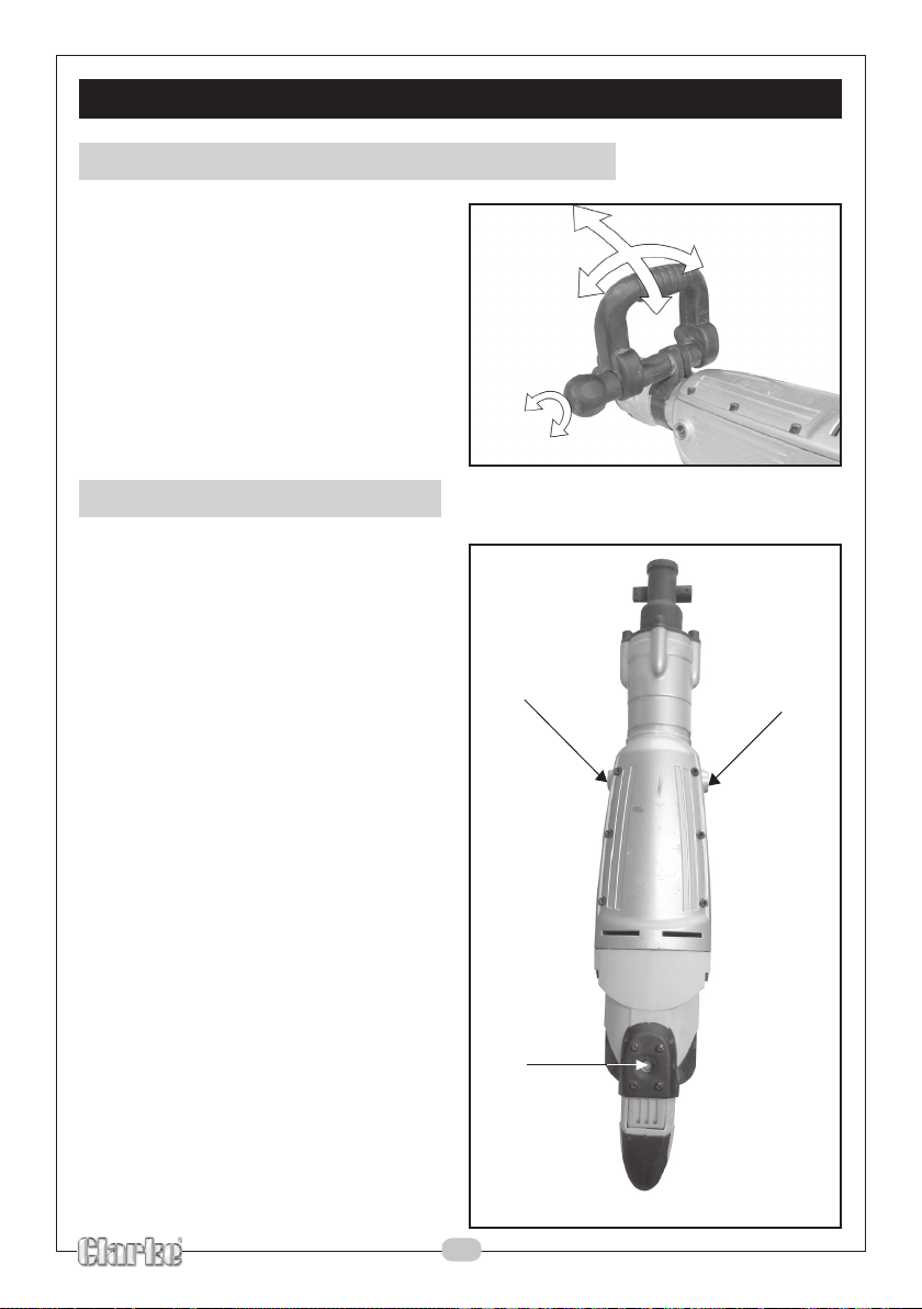
ADJUSTING D SHAPED HANDLE
1. Turn the clamp knob
anticlockwise to loosen the D
shaped handle.
2. Adjust the D shaped handle to
the required angle and position.
3. Rotate the clamp knob
clockwise to lock the D shaped
handle into position.
FITTING THE SIDE HANDLES
1. The side handle can be fitted to
one of 3 points on the demolition
hammer shown on figure 2.
Fig 1
Fig 2
2
1
6
Page 7
PREPARATION
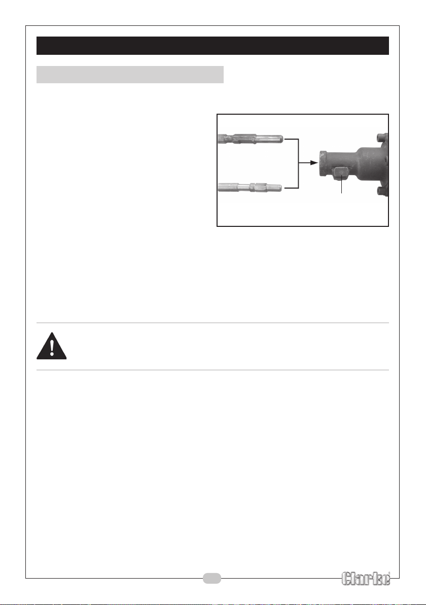
FITTING THE CHISEL/BIT
To fit the chisel/bit, proceed as follows:
1. Clean and grease the chisel
shank. Do NOT lubricate the
machine.
2. Pull out and rotate the locking
pin.
3. Insert the chisel shank into the
tool holder. Pull out and rotate
the locking pin again to secure
the chisel.
If the chisel bit you are using has a flat area on the shank, this should be
facing downwards.
4. Pull on the chisel to ensure it is locked into the tool holder, be aware that
the hammer action requires the chisel to be able to move axially by 2-3
cm.
WARNING!
Chisels/bits may be hot after use, take care when removing them from
the machine.
Fig 3
Locking
Pin
7
Page 8

INSTRUCTIONS FOR USE
WARNING!
Always check the location of pipes and wiring before starting the
machine.
Do not apply excessive pressure to the machine.
THE TRIGGER SWITCH
1. Pull the trigger switch up and back to start the machine.
2. Release the trigger to stop the machine.
Fig 4
Trigger
Speed
control
ADJUSTING THE SPEED
1. Adjust the speed control to the required setting.
MAINTENANCE
WARNING!
Make sure that the demolition hammer is switched off and disconnected
from the power supply before starting any cleaning or maintenance
procedures.
• Keep the cooling vents clear.
• Regularly clean the housing with a soft cloth.
• Any worn or damaged parts should be replaced by qualified personnel.
• Keep the handles clean and free from oil and grease.
8
Page 9

PARTS DIAGRAM
9
Page 10

PARTS LIST
metI rebmuNtraP noitpircseD ytQ metI rebmuNtraP noitpircseD ytQ
11000012NOCPK53X8MwercS4141400012NOCPKyeKrehtaeF1
22000012NOCPK8rehsaWgnirpS4242400012NOCPKetalPhctulC8
33000012NOCPK71
44000012NOCPK1X21X81rehsaW2444400012NOCPKraeGhtfiF1
55000012NOCPKtaeSgnirpS1545400012NOCPKtee
66000012NOCPKAgniR1646400012NOCPKraeGhtruoF1
77000012NOCPKgnirpS1747400012NOCPKetalPpilS1
88000012NOCPKteuoC18484
99000012NOCPKlaeSliO1949400012NOCPKrevoCeldeeN1
010100012NOCPKgniRO2050500012NOCPK6181KHgniraeB
111100012NOCPKgniRO2151500012NOCPKtfahSknarCdrihT1
212100012NOCPKeloPlletS4252500012NOCPK8X4BniP1
313100012NOCPKe
414100012NOCPKgniRpilC1454500012NOCPK04gniRpilC1
515100012NOCPK86gniRpi
616100012NOCPKgniraeBliO1656500012NOCPKetalPeldeeN1
717100012NOCPKelffaBgniraeBliO175750
818100012NOCPKgniRleetS1858500012NOCPK53X5MwercS2
919100012NOCPKdoR1959500012NOCPKgniR1M1
CPKgniRO1060600012NOCPK53X4TSwercS2
020200012NO
121200012NOCPKrehsaW1161600012NOCPKtaeSgnipmaD1
222200012NOCPKgnIRO3262600012NOCPKgnir
323200012NOCPKmaR1363600012NOCPKliaRerusolCgnipmaD1
424200012NOCPKelffaBmaR1464600012NOCPKrehsaW1
CPKelffaBliOtnorF1565600012NOCPKgniRpilC1
525200012NO
626200012NOCPKkcolBdaeD1666600012NOCPK2006gniraeBllaB1
727200012NOCPKkcolBde
828200012NOCPKrednilyC1868600012NOCPKrevoCraeG1
929200012NOCPKgniraeBliOkcalB1969600012NOCPKe
030300012NOCPKraeGxiS1070700012NOCPKrotoR1
131300012NOCPKmaR1171700012NOCPKrehsaW1
232300012NOCPK5X04gniRO227270001
333300012NOCPKniPnotsiP1373700012NOCPKtuN2
434300012NOCPKnotsiP1474700012NOCPKeldnaHediS1
535300012NOCPKdoRg
636300012NOCPKgniraeBeldeeN1676700012NOCPKrevoCliaT1
737300012NOCPK52x5MwercS477770
838300012NOCPK5rehsawgnirpS6878700012NOCPK5rehsaWgnirpS7
939300012NOCPK5rehsaW6979700012NOCPK61X5Mwe
040400012NOCPKrevoCesaCknarC1080800012NOCPK071X8MwercS1
X4niP1343400012NOCPKgnirpS8
hScitsalP1
00012NOCPKetalPeldeeN2
eldeeN2
veelSreniateR1353500012NOCPKraeGhtruoFdnoceS1
lC1555500012NOCPK1X81X53rehsaW2
0012NOCPKesaCknarC1
pSgnipmaD1
liforP1767600012NOCPKgniRO1
diuGnaF1
2NOCPKrotatS1
nitcennoC1575700012NOCPKklatStsujdA1
0012NOCPK5rehsaW7
rcS7
10
Page 11

PARTS LIST
metI rebmuNtraP noitpircseD ytQ metI rebmuNtraP noitpircseD ytQ
180800012NOCPKredloHeldnaHediS22012010012NOCPK81X4TSwercS7
281800012NOCPKpmalC13013010012NOCPKgnirpS2
382800012NOCPKeld
484800012NOCPKtuN15015010012NOCPKhsurBnobraC2
585800012NOCPK8MtuN616016010012NOCPK01X
686800012NOCPKrevoCtuN17017010012NOCPKhctiwS1
787800012NOCPKtuNtsujdA18018010012NOCPKFU22.0roticapaC1
88880001
989800012NOCPKF-61X6TSwercS40110110012NOCPKpilCdroC1
090900012NOCPKknalPtu
191900012NOCPKtloBthgiRtfiL12112110012NOCPK5X42gniRO4
292900012NOCPK0006gniraeBllaB1311311
393900012NOCPKteSgniraeBllaB14114110012NOCPKtekcaJdroC1
494900012NOCPKgnisuoH15115110012NOCPKdro
595900012NOCPK41X4TSwercS86116110012NOCPKeldnahtfiL1
696900012NOCPKrevoCliaTtfiL17117110012NOCPKxoBliO+esaerG1
797900
898900012NOCPKpilCdrawroFhctertS19119110012NOCPKelsihC1
999900012NOCPK01X
0010010012NOCPKscinortcelE11211210012NOCPK07X8.4TSwercS2
1011010012NOCPK03X8.4TSwercS12212
2NOCPK04X8MwercS49019010012NOCPKecnatcudnI1
012NOCPKdrawroFhctertS18118110012NOCPKreguA1
naHediSD14014010012NOCPKesuoHhsurB2
4TSwercS2
N11111110012NOCPK61X4TSwercS2
0012NOCPKeldnaHthgiR1
C1
4TSwercS10210210012NOCPKesaC1
210012NOCPKyeKrehtaeF2
PARTS & SERVICE
For Spare Parts and Service, please contact your nearest dealer, or CLARKE International,
PARTS & SERVICE TEL: 020 8988 7400
PARTS: parts@clarkeinternational.com
SERVICE: service@clarkeinternational.com
When disposing of this product, ensure it is disposed of according to all
local ordinances. It must not be disposed of with general household waste.
on one of the following numbers.
or e-mail as follows:
11
Page 12

VIBRATION EMISSIONS
HAND-ARM VIBRATION
Employers are advised to refer to the HSE publication “Guide for Employers”.
All hand held power tools vibrate to some extent, and this vibration is transmitted
to the operator via the handle, or hand used to steady the tool. Vibration from
about 2 to 1500 hertz is potentially damaging and is most hazardous in the range
from about 5 to 20 hertz.
Operators who are regularly exposed to vibration may suffer from Hand Arm
Vibration Syndrome (HAVS), which includes ‘dead hand’, ‘dead finger’, and
‘white finger’. These are painful conditions and are widespread in industries
where vibrating tools are used.
The health risk depends upon the vibration level and the length of time of
exposure to it……in effect, a daily vibration dose.
Tools are tested using specialised equipment, to approximate the vibration level
generated under normal, acceptable operating conditions for the tool in question.
For example, a grinder used at 45° on mild steel plate, or a sander on softwood
in a horizontal plane etc.
These tests produce a value ‘a
which represents the average vibration level of all tests taken, in three axes where
necessary, and a second figure ‘K’, which
represents the uncertainty factor, i.e. a value
in excess of ‘a’, to which the tool could
vibrate under normal conditions. These
values appear in the specification panel
below.
You will note that a third value is given in the
specification - the highest measured
reading in a single plane. This is the maximum
level of vibration measured during testing in
one of the axes, and this should also be
taken into account when making a risk
assessment.
‘
a
’ values in excess of 2.5 m/s2 are considered hazardous when used for prolonged
periods. A tool with a vibration value of 2.8 m/s2 may be used for up to 8 hours
(cumulative) per day, whereas a tool with a value of 11.2 m/s2 may be used for
½ hour per day only.
The graph shows the vibration value against the maximum time the respective
tool may be used, per day.
’
, expressed in metres per second per second,
12
Page 13

VIBRATION EMISSIONS
The uncertainty factor should also be taken into account when assessing a risk.
The two figures ‘a’ and ‘K’may be added together and the resultant value used
to assess the risk.
It should be noted that if a tool is used under abnormal, or unusual conditions, then
the vibration level could possibly increase significantly. Users must always take this
into account and make their own risk assessment, using the graph above as a
reference.
Some tools with a high vibration value, such as impact wrenches, are generally
used for a few seconds at a time, therefore the cumulative time may only be in
the order of a few minutes per day. Nevertheless, the cumulative effect,
particularly when added to that of other hand held power tools that may be
used, must always be taken into account when the total daily dose rate is
determined.
Declared vibration emission value in accordance with EN12096
Measured vibration emission value -
Values determined according to EN28622-1
a:
9.97 m/s
2
13
Page 14

14
Page 15

15
Page 16

 Loading...