

Page 1
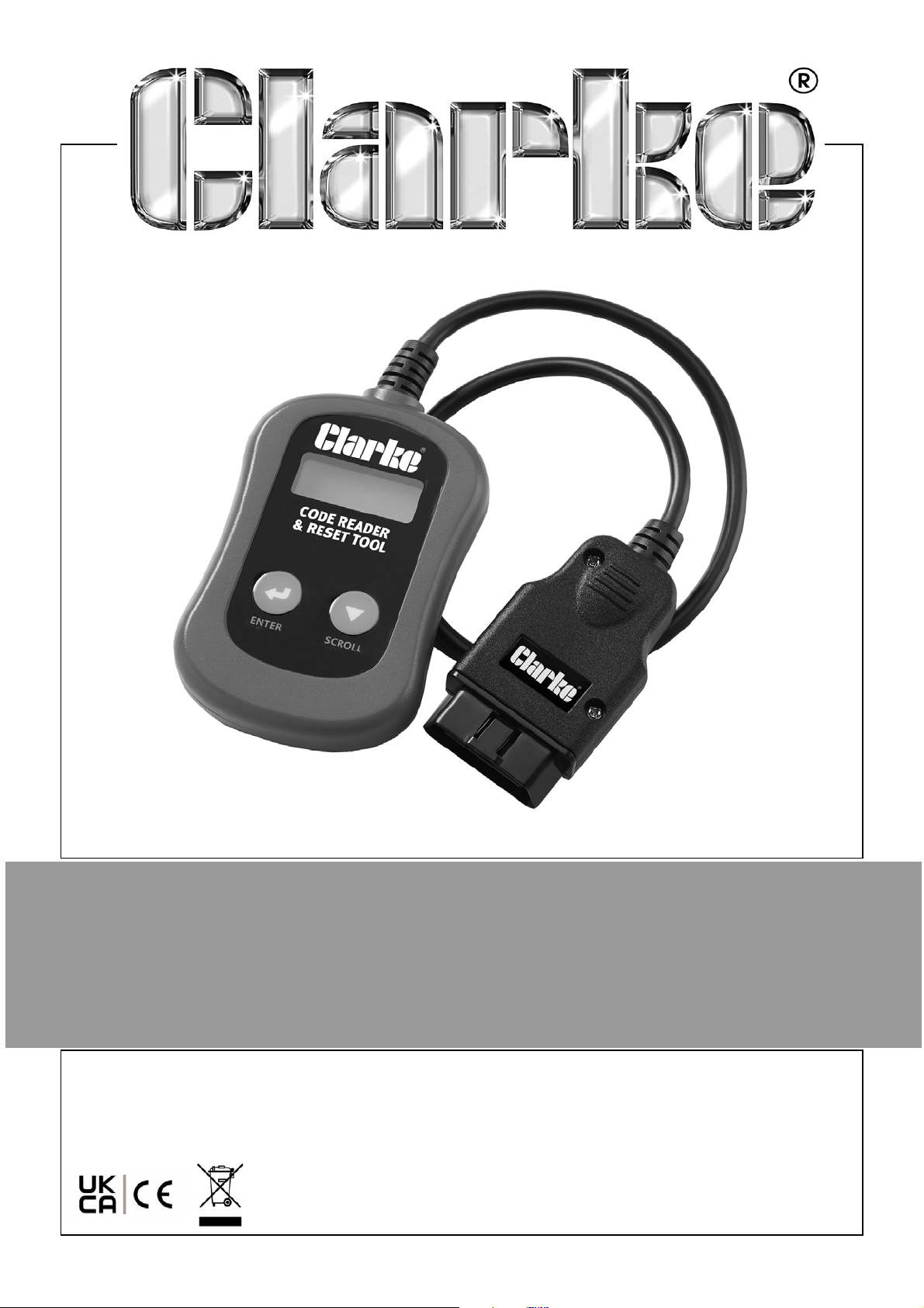
ENGINE FAULT CODE READER
MODEL NO: COBDII-E
PART NO: 4501141
USER INSTRUCTIONS
ORIGINAL INSTRUCTIONS DL0324
Page 2
INTRODUCTION
Thank you for purchasing this CLARKE Engine and Transmission Fault Code
Reader.
Please read this manual thoroughly, before attempting to operate and
carefully follow all instructions given.
It is vitally important that ALL precautions are taken, as specified, which will not
only provide protection for yourself and that of others around you, but will also
ensure that the code reader will give you long and satisfactory service.
GUARANTEE
This CLARKE product is guaranteed against faulty manufacture for a period of
12 months from the date of purchase. Please keep your receipt as proof of
purchase.
This guarantee is invalid if the product is found to have been abused or
tampered with in any way, or not used for the purpose for which it was
intended.
Faulty goods should be returned to their place of purchase, no product can
be returned to us without prior permission.
This guarantee does not effect your statutory rights.
ENVIRONMENTAL RECYCLING POLICY
Through purchase of this product, the customer is taking on the
obligation to deal with the WEEE in accordance with the WEEE
regulations in relation to the treatment, recycling & recovery and
environmentally sound disposal of the WEEE.
In effect, this means that this product must not be disposed of with general
household waste. It must be disposed of according to the laws governing
Waste Electrical and Electronic Equipment (WEEE) at a recognised disposal
facility.
If disposing of this product or any damaged components, do not dispose of
with general waste. This product contains valuable raw materials. Metal
products should be taken to your local civic amenity site for recycling of metal
products.
2
Parts & Service: 020 8988 7400 / E-mail: [email protected] or [email protected]
Page 3
PRODUCT OVERVIEW
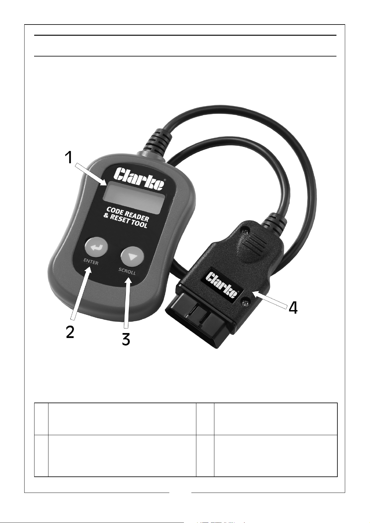
1 LCD Display - Indicates test results. It is
a backlit 2 line display with 8
characters on each line.
2 Enter Button - Confirms a selection or
action from a menu list, or returns to
the main menu.
3
Parts & Service: 020 8988 7400 / E-mail: [email protected] or [email protected]
3 Scroll Button - Scrolls through
the menu items or cancels an
operation.
4 OBDII 16 Pin Connector -
Connects the code scanner to
the vehicles Data Link
Connector (DLC)
Page 4
SPECIFICATIONS
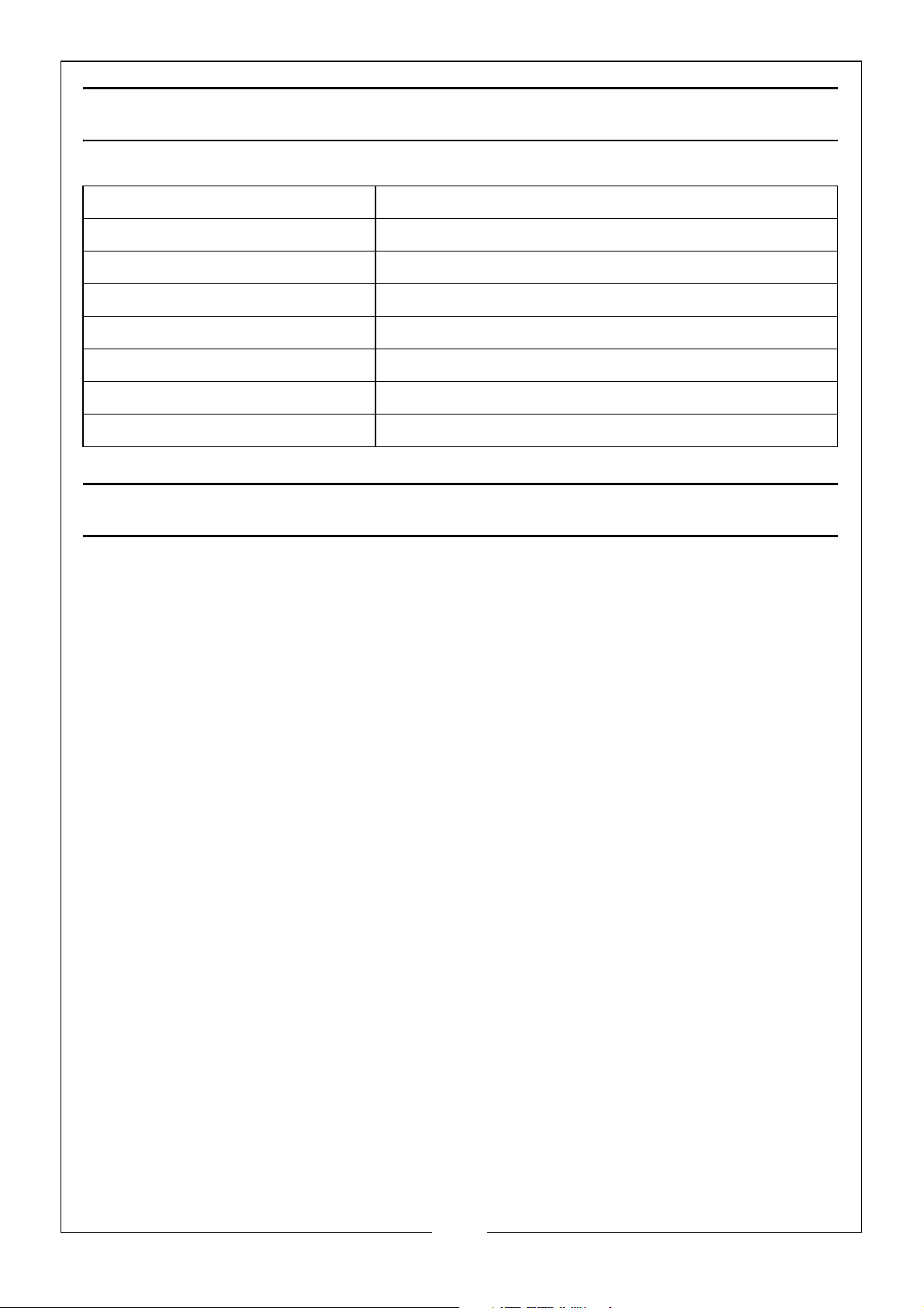
Model Number COBDII-E
Operating Power DC12V provided via the vehicles battery
Operating Temperature 0°C to 50°C
Storage Temperature -20°C to 70°C
Display Backlit LCD, 2 Lines, 8 Characters per Line
Cable Length 480mm
Dimensions (LxWxD) 130mm x 70mm x 20mm
Weight 133g
FUNCTION DESCRIPTION
1. Works with all 1996 and newer cars & light trucks/vans that are OBD II
compliant (including the CAN, VPW, PWM, ISO and KWP 2000 protocols).
2. Reads and clears generic and manufacturers specific Diagnostic Trouble
Codes (DTC) and turns off the check engine light.
3. Supports multiple trouble code requests: generic codes, pending codes
and manufacturers specific codes.
4. Reviews the emission readiness status of OBD monitors.
5. Retrieves VIN (Vehicle Identification Number) on 2002 and newer vehicles
that support Mode 9.
6. Determines the malfunction indicator lamp (MIL) status
7. Powered by the vehicle battery via the OBD II cable.
4
Parts & Service: 020 8988 7400 / E-mail: [email protected] or [email protected]
Page 5

SAFETY PRECAUTIONS
PLEASE READ BEFORE USING THIS UNIT
1. ALWAYS perform automotive testing in a safe environment.
2. Keep clothing, hair, hands, tools, test equipment, etc, away from all
moving or hot engine parts.
3. Operate the vehicle in a well-ventilated work area; Exhaust gases are
poisonous.
4. Put chocks under drive wheels and NEVER leave the vehicle unattended
while running tests.
5. ALWAYS use extreme caution when working around the ignition coil,
distributor cap, ignition wires and spark plugs. These components create
hazardous voltages when the engine is running.
6. Put transmission in PAR K (for automatic transmission) or NEUTRAL (for manual
transmission) and make sure the parking/hand brake is engaged.
7. Keep a fire extinguisher suitable for gasoline/chemical/electrical fires
nearby.
8. DO NOT connect or disconnect any test equipment with ignition on or
engine running.
CARE AND MAINTENANCE
Keep the code reader dry, clean and free from oil, water and grease. Use a
mild detergent on a clean cloth to clean the outside of the code reader,
when necessary.
Keep the 16 pin connector clean and the cable tidy.
ALWAYS check for splits or cuts in the cable.
5
Parts & Service: 020 8988 7400 / E-mail: [email protected] or [email protected]
Page 6
GENERAL INFORMATION
VEHICLE COVERAGE
The OBDII Code Reader is specially designed to work with all OBDII compliant
vehicles, including those equipped with the next-generation protocol - Control
Area Network (CAN). It is required by UK & EU regulations that all petrol
vehicles since January 2001 and all diesel vehicles since January 2004 must be
OBD II compliant which includes all American, Asian and European vehicles.
To verify if your vehicle is compliant, check the Vehicle Emissions Control
Information (VECI) label which should be located under the bonnet or by the
radiator of most vehicles. If the vehicle is OBD II compliant, the label will
designate ‘OBD II Certified’. Additional, regulations mandate that all OBD II
complaint vehicles must have a common sixteen pin Data Link
Connector (DLC), usually located under the dashboard.
OBDII COMPLIANT CAR MANUFACTURERS
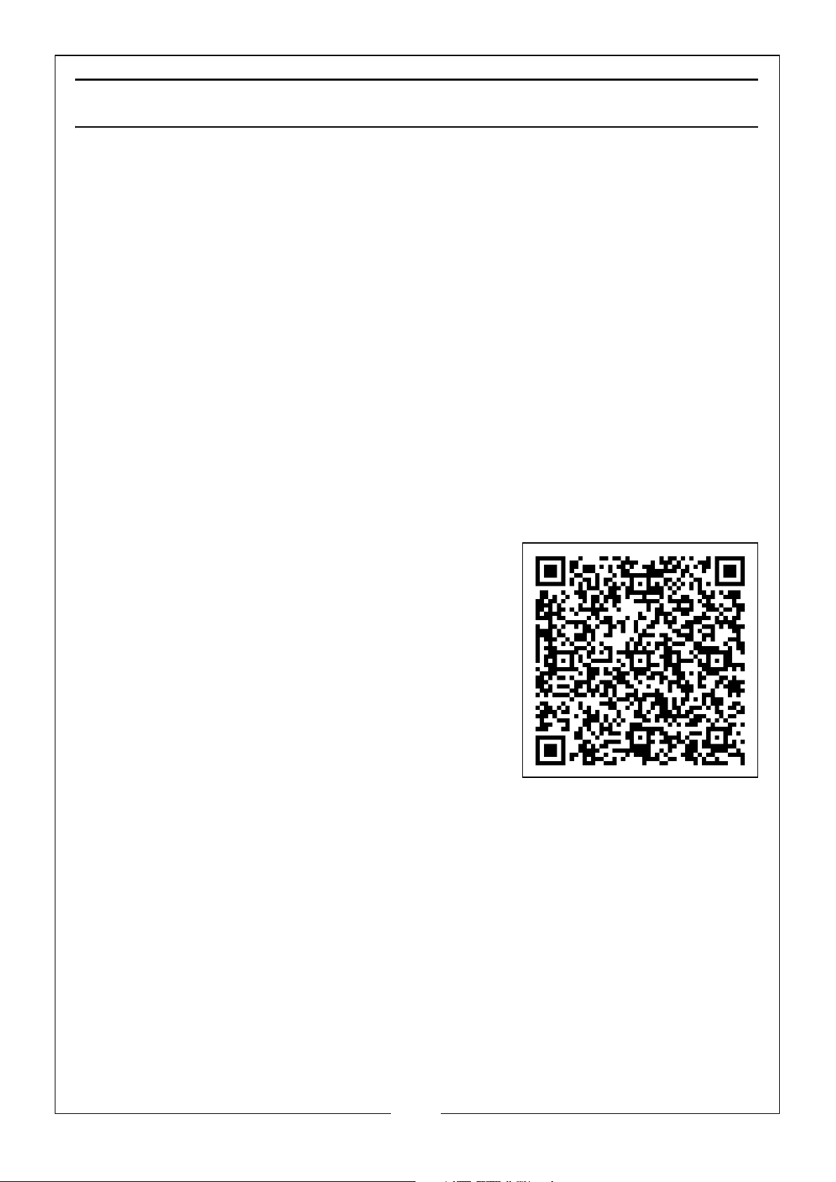
For a full list of make and models of compliant manufacturers download the
spreadsheet using the following website or QR code.
http://www.clarkeinternational.com/media/
1371/obdii-compliant-car-list-for-cobdii-faultcode-reader.xls
DIAGNOSTIC TROUBLE CODES (DTC)
OBDII Diagnostic Trouble Codes are stored by the on-board computer
diagnostic system in response to a problem found in the vehicle. These codes
identify a particular problem area and are intended to provide you with a
guide as to where a fault might be occurring within a vehicle. OBDII Diagnostic
Trouble Codes consist of a five-digit alphanumeric code. The first character, a
letter, identifies which control system sets the code. The other four characters,
all numbers, provide additional information on where the DTC originated and
the operating conditions that caused it to set. Here is an example to illustrate
the structure of the digits:
6
Parts & Service: 020 8988 7400 / E-mail: [email protected] or [email protected]
Page 7
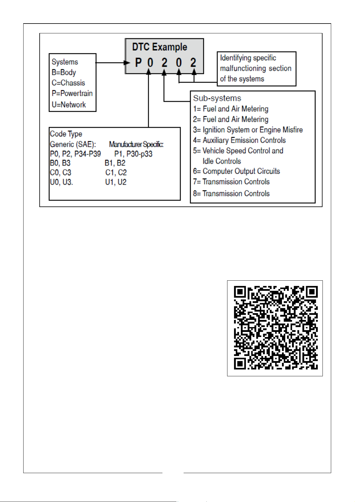
NOTE: Manufacturer Specific Codes(x1xxx): This is where the vehicle
manufacturer feels that a code is not available within the generic list.
The definitions for these are set by the vehicle manufacturer.
For a list of OBD II generic DTC Definitions, see the list on pages 16 -40, or
download the spreadsheet using the following website or QR code.
http://www.clarkeinternational.com/media/1372/
dtc-codes-for-cobdii-fault-code-reader.xlsx
OBDII READINESS MONITORS
An important part of a vehicle's OBDII system are the Readiness monitors,
which are indicators used to find out if all of the emissions components have
been evaluated by the OBDII system. They run periodic tests on specific
systems and components to ensure that they are performing within allowable
limits.
7
Parts & Service: 020 8988 7400 / E-mail: [email protected] or [email protected]
Page 8

Currently, there are eleven OBDII Readiness Monitors (or I/M Monitors) defined.
Not all monitors are supported by all vehicles and the exact number of
monitors in any vehicle depends on the motor vehicle manufacturer's
emissions control strategy.
CONTINUOUS MONITORS
Some of the vehicle components or systems are continuously tested by the
vehicle's OBDII system, while others are tested only under specific vehicle
operating conditions. The continuously monitored components listed below
are always ready:
1. Misfire
2. Fuel System
3. Comprehensive Components Monitors (CCM)
Once the vehicle is running, the OBDII system is continuously checking the
above components, monitoring key engine sensors, watching for engine
misfire, and monitoring fuel demands.
NON CONTINUOUS MONITORS
Unlike the continuous monitors, many emissions and engine system
components require the vehicle to be operated under specific conditions
before the monitor is ready. These monitors are termed non-continuous
monitors and are listed below:
1. EGR System
2. O2 Sensors
3. Catalyst
4. Evaporative System
5. O2 Sensor Heater
6. Secondary Air
7. Heated Catalyst
8. A/C System
OBDII MONITOR READINESS STATUS
OBDII systems must indicate whether or not the vehicle's PCM monitor system
has completed testing on each component. Components that have been
tested will be reported as Ready or Complete, meaning they have been
tested by the OBDII system. The purpose of recording readiness status is to
allow inspectors to determine if the vehicle's OBDII system has tested all the
components and/or systems.
8
Parts & Service: 020 8988 7400 / E-mail: [email protected] or [email protected]
Page 9

The powertrain control module (PCM) sets a monitor to Ready or Complete
after an appropriate drive cycle has been performed. The drive cycle that
enables a monitor and sets readiness codes to ready varies for each individual
monitor. Once a monitor is set as Ready or Complete, it will remain in this state.
A number of factors, including erasing of diagnostic trouble codes (DTCs) with
a scan tool or a disconnected battery, can result in Readiness Monitors being
set to Not Ready. Since the three continuous monitors are constantly
evaluating, they will be reported as Ready all of the time. If testing of a
particular supported non-continuous monitor has not been completed, the
monitor status will be reported as Not Complete or Not Ready.”
In order for the OBD monitor system to become ready, the vehicle should be
driven under a variety of normal operating conditions. These operating
conditions may include a mix of highway driving and stop and go, city type
driving, and at least one overnight-off period. For specific information on
getting your vehicle's OBD monitor system ready, please consult your vehicle
owner’s manual.
OBDII DEFINITIONS
POWERTRAIN CONTROL MODULE (PCM)
OBDII terminology for the on-board computer that controls engine and drive
train.
MALFUNCTION INDICATOR LIGHT (MIL)
Malfunction Indicator Light (Service Engine Soon, Check Engine) is a term used
for the light on the instrument panel. It is to alert the driver and/or the repair
technician that there is a problem with one or more of vehicle's systems and
may cause emissions to exceed standards. If the MIL illuminates with a steady
light, it indicates that a problem has been detected and the vehicle should be
serviced as soon as possible. Under certain conditions, the dashboard light will
blink or flash. This indicates a severe problem and flashing is intended to
discourage vehicle operation. The vehicle on-board diagnostic system can
not turn the MIL off until the necessary repairs are completed or the condition
no longer exists.
DIAGNOSTIC TROUBLE CODES (DTC)
Diagnostic Trouble Codes (DTC) that identify which section of the emission
control system has malfunctioned.
ENABLING CRITERIA
Also termed Enabling Conditions. They are the vehicle specific events or
conditions that must occur within the engine before the various monitors will
set or run. Some monitors require the vehicle to follow a prescribed drive cycle
routine as part of the enabling criteria. Drive cycles vary among vehicles and
for each monitor in any particular vehicle.
9
Parts & Service: 020 8988 7400 / E-mail: [email protected] or [email protected]
Page 10
OBDII DRIVE CYCLE
A specific mode of vehicle operation that provides condition required to set all
the readiness monitors applicable to the vehicle to the ready condition. The
purpose of completing an OBDII drive cycle is to force the vehicle to run its
on-board diagnostics. Some form of a drive cycle needs to be performed after
DTCs have been erased from the PCM's memory or after the battery has been
disconnected. Running through a vehicle's complete drive cycle will set the
readiness monitors so that future faults can be detected. Drive cycles vary
depending on the vehicle and the monitor that needs to be reset. For vehicle
specific drive cycle, consult the vehicle's Owner's Manual.
OPERATING PROCEDURES
WARNING: DO NOT CONNECT OR DISCONNECT ANY TEST EQUIPMENT
WITH THE IGNITION ON AND THE ENGINE RUNNING.
READING CODES
The power of the code reader is provided via the vehicle data link connector
(DLC). Follow the steps below to turn on the code reader:
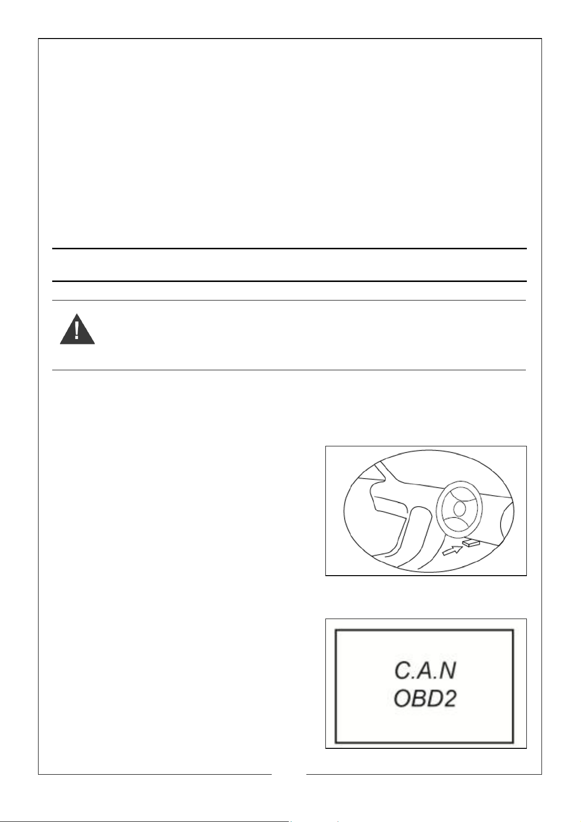
1. The DLC is usually located
approximately 12 inches from the
centre of the instrument panel
(dashboard), under or around the
drivers side for most vehicles. Consult
the vehicles handbook for exact
location.
2. Make sure the vehicle ignition is ‘OFF’
3. Plug the OBDII 16 pin data link
connector into the vehicles DLC port.
4. Wait for the LCD display to read
‘C.A.N.OBD2’
5. Turn the ignition ‘ON’, but DO NOT start
the engine.
10
Parts & Service: 020 8988 7400 / E-mail: [email protected] or [email protected]
Page 11
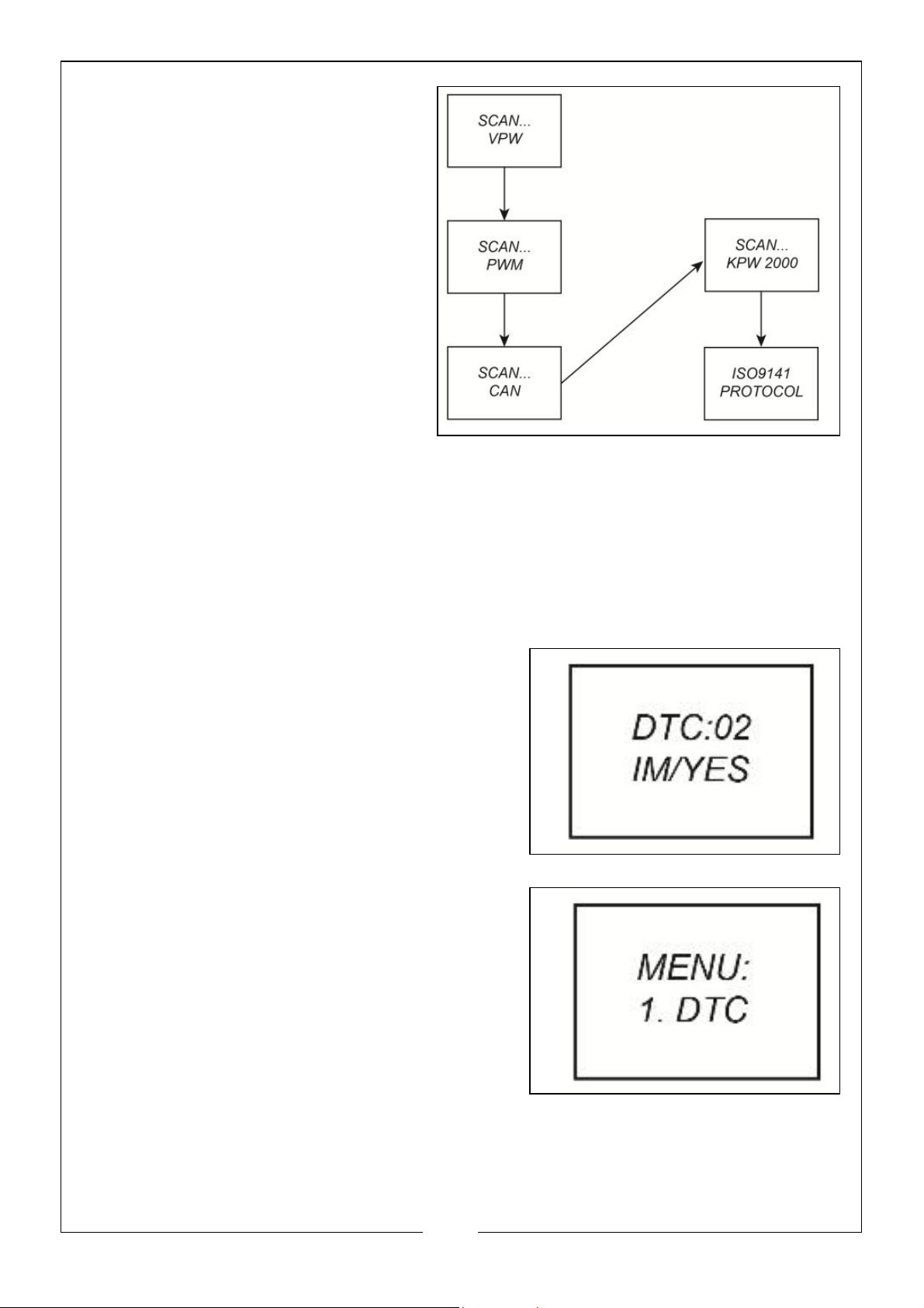
6. Press the ‘ENTER’ button. A
sequence of messages
showing the OBDII protocols
will be observed on the display
until the vehicle protocol is
detected.
• Not all these messages will
be displayed unless the
protocol of the vehicle
being tested is the last one ISO9141 protocol. They will
stop appearing after the
vehicle protocol is
detected and confirmation
message of ‘XXX Protocol’ is
displayed.
• If a ‘LINK ERROR’ message shows up, turn the ignition ‘OFF’ for about 10
seconds, check if the OBDII connector is securely connected to the
vehicles DLC, and then turn the ignition back to ‘ON’. Repeat the
procedure from step 6. If the ‘LINK ERROR’ message does not go away,
then there may be a problem with OBDII tester communicating with the
vehicle.
7. Wait fro the main menu to come up
after a brief overview displaying the
scanning results with the total number of
DTC’s and the overall I/M monitor status.
8. Select ‘DTC’ from the main menu by
pressing the ‘ENTER’ button
11
Parts & Service: 020 8988 7400 / E-mail: [email protected] or [email protected]
Page 12
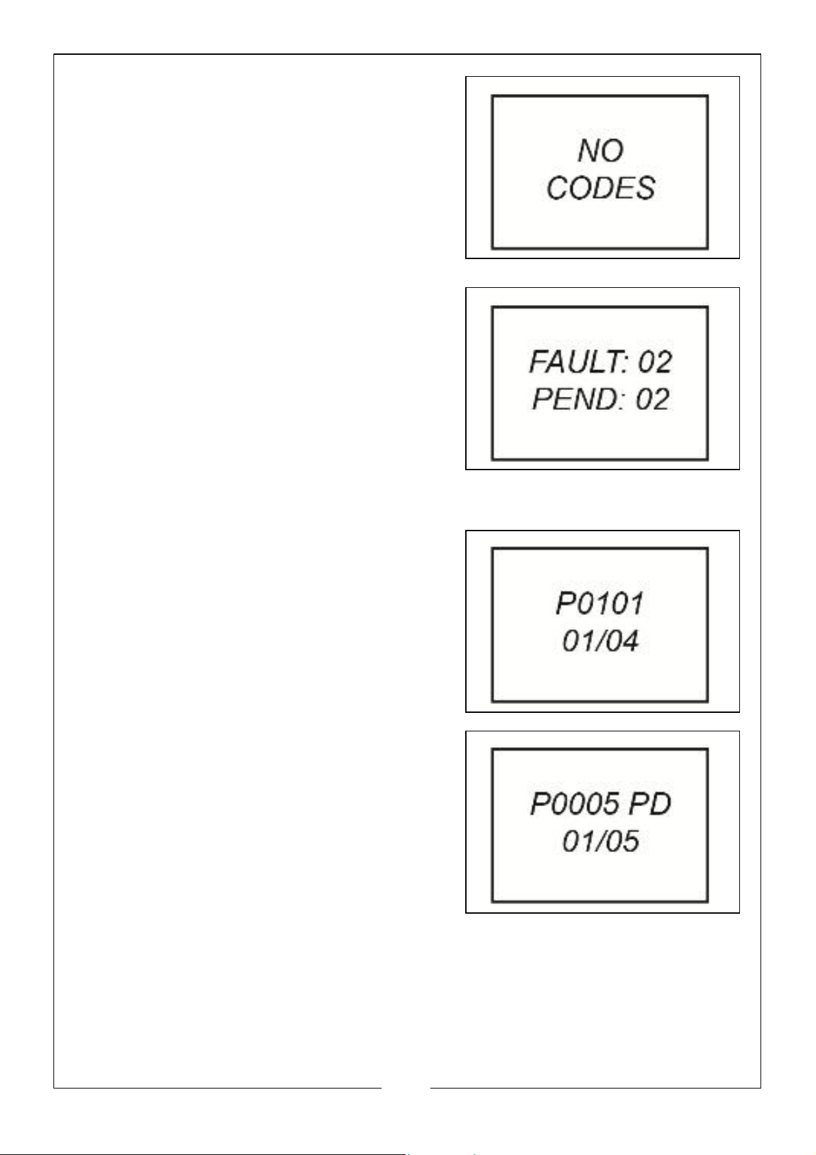
• If there are no Diagnostic Trouble
Codes retrieved, the display will
indicate ‘NO CODES’
• If there are any Diagnostic Trouble
Codes, then the total number of fault
codes followed by that of the
pending codes will be reported on
the display.
9. Read the Diagnostic Trouble Codes by pressing the ‘SCROLL’ button.
• The first code number will appear on
the first line of the LCD display, the
numerical sequence of the code and
the total number of the codes stored
will appear on the second line. To
view additional codes, press the
‘SCROLL’ button to scroll as
necessary, until all the codes have
been shown.
• If the code retrieved is a pending
code, a ‘PD’ will show on the LCD
display at the end.
• To view previous codes, press the
‘SCROLL’ button to scroll through to
the end, and then start from the first
on the list.
10. Look up the Diagnostic Trouble Code on
pages 16 to 40. If the code displayed is
not listed, contact the vehicle manufacturer or a certified mechanic for
more help.
12
Parts & Service: 020 8988 7400 / E-mail: [email protected] or [email protected]
Page 13
ERASE CODES
WARNING: ERASING THE DTC CODES ALLOWS THE SCAN TOOL TO DELETE
NOT ONLY THE CODES FROM THE VEHICLES ON-BOARD COMPUTER, BUT
ALSO ‘FREEZE FRAME’ DATA AND MANUFACTURER SPECIFIC ENHANCED
DATA. FURTHER, THE I/M READINESS MONITOR STATUS FOR ALL VEHICLE
MONITORS IS RESET TO NOT READY OR NOT COMPLETE STATUS. DO NOT
ERASE THE CODES BEFORE THE SYSTEM HAS BEEN CHECKED COMPLETELY
BY A CERTIFIED MECHANIC.
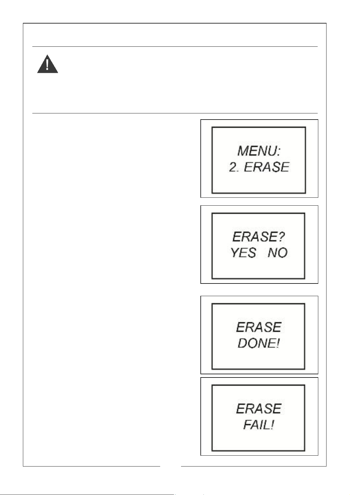
1. If you decide to erase the DTC’s, select
‘2. ERASE’ from the main menu by
pressing the ‘ENTER’ button.
• If the scan tool is not connected or no
communication is established with
the vehicle yet, then refer to
‘READING CODES’ on pages 10 - 12.
2. A message of ‘ERASE? YES NO’ will
appear asking for your confirmation.
3. If you do not want to proceed with
erasing the codes, press the ‘SCROLL’
button to exit.
4. If you do wish to proceed to erase the
codes, then press the ‘ENTER’ button.
5. If the codes are cleared successfully,
then an ‘ERASE DONE!’ message will
show on the display. Press the ‘ENTER’
button to return to the main menu list.
6. If the codes are not cleared, then an
‘ERASE FAIL!’ message will appear.
• HOT KEY: Press and hold the ‘SCROLL’
button for about 3 seconds. This will
allow you to erase the DTC’s more
quickly than through the main menu.
13
Parts & Service: 020 8988 7400 / E-mail: [email protected] or [email protected]
Page 14
RETRIEVE I/M READINESS STATUS
WARNING: I/M READINESS FUNCTION IS USED TO CHECK THE
OPERATIONS OF THE EMISSION SYSTEM ON OBD II COMPLIANT VEHICLES.
IT IS AN EXCELLENT FUNCTION TO USE PRIOR TO HAVING A VEHICLE
INSPECTED FOR COMPLIANCE TO VEHICLE EMISSIONS REGULATIONS. AN
I/M READINESS STATUS RESULTS OF ‘NO’ DOES NOT NECESSARILY
INDICATE THAT THE VEHICLE BEING TESTED WILL FAIL THE I/M INSPECTION.
• YES - all monitors supported on the vehicle have completed their
diagnostic testing and the MIL light is not on.
• NO - at least one monitor supported on the vehicle has not completed
its diagnostic testing, and/or the ‘Check Engine’ (MIL) light is on.
• READY - indicates that a particular monitor being checked has
completed its diagnostic testing.
• Not RDY (NOT READY) - indicates that a particular monitor being
checked has not completed its diagnostic testing.
• N/A - the monitor is not supported on this vehicle.
• FLASHING RIGHT ARROW - indicates additional information is available
on the next screen.
• FLASHING LEFT ARROW - indicates additional information is available on
the previous screen.
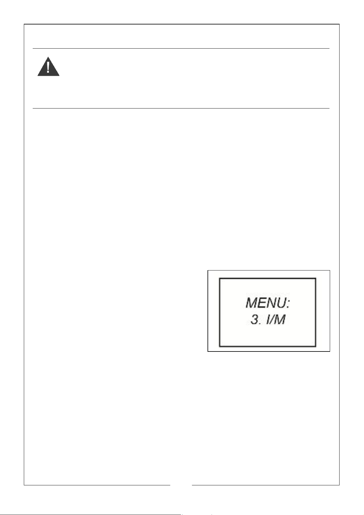
1. Select ‘3. I/M’ from the main menu by
pressing the ‘ENTER’ button.
• If the scan tool is not connected or no
communication is established with
the vehicle yet, then refer to
‘READING CODES’ on pages 10 - 12.
2. Use the ‘SCROLL’ button to view the
status of the MIL light (ON or OFF) and
the following monitors:
• MISFIRE - Misfire Monitor
• FUEL - Fuel System Monitor
• CCM - Comprehensive Components Monitor
• CAT - Catalyst Monitor
• HCM - Heated Catalyst Monitor
• EVAP - Evaporative System Monitor
• 2AIR - Secondary Air Monitor
• A/C - A/C System Monitor
14
Parts & Service: 020 8988 7400 / E-mail: [email protected] or [email protected]
Page 15
• O2S - O2 Sensors Monitor
• HO2S - OS Sensor Heater Monitor
• EGR - EGR System Monitor
3. Press the ‘ENTER’ button to return to the main menu.
VIEW VIN NUMBER
The View VIN function allows you to retrieve the vehicle identification number
on 2002 and newer vehicles that support Mode 9.
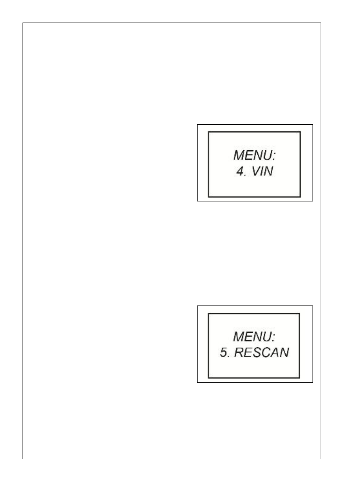
1. Select ‘4. VIN’ from the main menu by
pressing the ‘ENTER’ button.
• If the scan tool is not connected or no
communication is established with
the vehicle yet, then refer to
‘READING CODES’ on pages 10 - 12.
2. Use the ‘SCROLL’ button to view
additional digits of the 17 digit string.
• FLASHING RIGHT ARROW - indicates additional information is available
on the next screen.
• FLASHING LEFT ARROW - indicates additional information is available on
the previous screen.
3. Press the ‘ENTER’ button to return to the main menu.
RESCAN DATA
The RESCAN function allows you to retrieve the most current data stored in the
ECM or to re-link to the vehicle if communication is disconnected.
1. Select ‘5. RESCAN’ from the main menu
by pressing the ’ENTER’ button.
• If the scan tool is not connected or no
communication is established with
the vehicle yet, then refer to
‘READING CODES’ on pages 10 - 12.
2. Use either the ‘SCROLL’ or ‘ENTER’
button to return to the main menu.
15
Parts & Service: 020 8988 7400 / E-mail: [email protected] or [email protected]
Page 16
DIAGNOSTIC TROUBLE CODES - P0001 - P0040
P0001 Fuel Volume Regulator Control Circuit Open
P0002 Fuel Volume Regulator Control Circuit Range/Pe rformance
P0003 Fuel Volume Regulator Control Circuit Low
P0004 Fuel Volume Regulator Control Circuit High
P0005 Fuel Shutoff Val ve . A Control Circuit Open
P0006 Fuel Shutoff Val ve . A Control Circuit Low
P0007 Fuel Shutoff Val ve . A Control Circuit High
P0008 Engine Posi ti on System Pe rformance ( Bank 1)
P0009 Engine Posi ti on System Pe rformance ( Bank 2)
P0010 Camshaft Position Actuator A - Bank 1 Circuit Mal functi on
P0011 Camshaft Position Actuator A - Bank 1 Ti ming Over-Advanced
P0012 Camshaft Position Actuator A - Bank 1 Ti mi ng Over-Retarded
P0013 Camshaft Position Actuator B - Bank 1 Circuit Mal functi on
P0014 Camshaft Position Actuator B - Bank 1 Ti ming Over-Advanced
P0015 Camshaft Position Actuator B - Bank 1 Ti ming Over-Re tarded
P0016 Cam/Crankshaft Pos. Corre lation Se nsor A - Bank 1
P0017 Cam/Crankshaft Pos. Corre lation Se nsor B - Bank 1
P0018 Cam/Crankshaft Pos. Corre lation Se nsor A - Bank 2
P0019 Cam/Crankshaft Pos. Corre lation Se nsor B - Bank 2
P0020 Camshaft Position Actuator A - Bank 2 Circuit Malfunction
P0021 Camshaft Position Actuator A - Bank 2 Ti mi ng Over-Advanced
P0022 Camshaft Position Actuator A - Bank 2 Ti ming Over-Retarded
P0023 Camshaft Position Actuator B - Bank 2 Circuit Mal functi on
P0024 Camshaft Position Actuator B - Bank 2 Ti ming Over-Advanced
P0025 Camshaft Position Actuator B - Bank 2 Ti ming Over-Re tarded
P0026 Intake V alve -Bank 1 Control Sole noi d CKT Range /Perf ormance
P0027 Exhaust V alve -Bank 1 Control Sole noi d CKT Range /Pe rformance
P0028 Intake V alve -Bank 2 Control Sole noi d CKT Range /Perf ormance
P0029 Exhaust V alve -Bank 2 Control Sole noi d CKT Range /Pe rformance
P0030 HO2S Bank 1 Se nsor 1 He ater Circuit
P0031 HO2S Bank 1 Se nsor 1 He ater Circuit Low
P0032 HO2S Bank 1 Se nsor 1 He ater Circuit Hi gh
P0033 Turbo/SupWaste gate Control Ci rcui t
P0034 Turbo/SupWaste gate Control Ci rcui t Low
P0035 Turbo/SupWaste gate Control Ci rcui t High
P0036 HO2S Bank 1 Se nsor 2 He ater Circuit
P0037 HO2S Bank 1 Se nsor 2 He ater Circuit Low
P0038 HO2S Bank 1 Se nsor 2 He ater Circuit Hi gh
P0039 Turbo/Super Charger Bypass Control CKT Performance
P0040 O2 Bank 1 Se nsor 1 Signal s Swapped w/ O2 Bank 2 Sensor 1
Parts & Service: 020 8988 7400 / E-mail: [email protected] or [email protected]
16
Page 17
DIAGNOSTIC TROUBLE CODES - P0041 - P0080
P0041 O2 Bank 1 Sensor 2 Signals Swapped w/ O2 Bank 2 Sensor 2
P0042 HO2S Bank 1 Sensor 3 He ater Circuit
P0043 HO2S Bank 1 Sensor 3 He ater Circuit Low
P0044 HO2S Bank 1 Sensor 3 He ater Circuit Hi gh
P0045 Turbo/Super Charger Boost Control Solenoid A Circuit Open
P0046 Turbo/Super Charger Boost Control Solenoid A Circuit Range/ Perform
P0047 Turbo/Super Charger Boost Control Solenoid A Circuit Low
P0048 Turbo/Super Charger Boost Control Solenoid A Circuit High
P0049 Turbo/Super Charger Boost Input/Turbine Speed Overspeed
P0050 HO2S Bank 2 Sensor 1 He ater Circuit
P0051 HO2S Bank 2 Sensor 1 He ater Circuit Low
P0052 HO2S Bank 2 Sensor 1 He ater Circuit Hi gh
P0053 HO2S Bank 1 Sensor 1 He ater Re si stance
P0054 HO2S Bank 1 Sensor 2 He ater Re si stance
P0055 HO2S Bank 1 Sensor 3 He ater Re si stance
P0056 HO2S Bank 2 Sensor 2 He ater Circuit
P0057 HO2S Bank 2 Sensor 2 He ater Circuit Low
P0058 HO2S Bank 2 Sensor 2 He ater Circuit Hi gh
P0059 HO2S Bank 2 Sensor 1 He ater Re si stance
P0060 HO2S Bank 2 Sensor 2 He ater Re si stance
P0061 HO2S Bank 2 Sensor 3 He ater Re si stance
P0062 HO2S Bank 2 Sensor 3 He ater Circuit
P0063 HO2S Bank 2 Sensor 3 He ater Circuit Low
P0064 HO2S Bank 2 Sensor 3 He ater Circuit Hi gh
P0065 Air Assisted Injector. Control Range/Performance
P0066 Air Assisted Injector. Control Circuit Low
P0067 Air Assisted Injector. Control Circuit High
P0068 MAF/MAP Sensor Throttle Position Correlation
P0069 MAP/BARO Correlation
P0070 Ambient Air Temp. Sensor Circuit
P0071 Ambient Air Temp. Sensor Range/Performance
P0072 Ambient Air Temp. Sensor Circuit Low
P0073 Ambient Air Temp. Sensor Circuit High
P0074 Ambient Air Temp. Sensor CKT Intermittent
P0075 Intake Val ve -Bank 1 Control Circuit
P0076 Intake Val ve -Bank 1 Control Circuit Low
P0077 Intake Val ve -Bank 1 Control Circuit High
P0078 Exhaust Valve-Bank1 Control Circuit
P0079 Exhaust Valve-Bank1 Control Circuit Low
P0080 Exhaust Valve-Bank1 Control Circuit High
Parts & Service: 020 8988 7400 / E-mail: [email protected] or [email protected]
17
Page 18
DIAGNOSTIC TROUBLE CODES - P0081 - P0120
P0081 Intake Valve -Bank 2 Control Circuit
P0082 Intake Valve -Bank 2 Control Circuit Low
P0083 Intake Valve-Bank 2 Control Circuit High
P0084 Exhaust Valve-Bank2 Control Circuit
P0085 Exhaust Valve -Bank2 Control Circuit Low
P0086 Exhaust Valve -Bank2 Control Circuit High
P0087 Fuel Rail Pressure Too Low
P0088 Fuel Rail Pressure Too High
P0089 Fuel Pressure Regulator 1 Performance
P0090 Fuel Pre ssure Regulator 1 Control Circuit
P0091 Fuel Pressure Regulator 1 Control Circuit Low
P0092 Fuel Pressure Regulator 1 Control Circuit High
P0093 Fuel System Leak (Large)
P0094 Fuel System Leak (Small)
P0095 IAT Sensor 2 Circuit
P0096 IAT Sensor 2 CKT Range/Performance
P0097 IAT Sensor 2 Circuit Low
P0098 IAT Sensor 2 Circuit High
P0099 IAT Sensor 2 CKT Intermittent
P0100 MAF or VAF A Circuit Malfunction
P0101 MAF or VAF A Circuit Range/Performance
P0102 MAF or VAF A Circuit Low Input
P0103 MAF or VAF A Circuit High Input
P0104 MAF or VAF A Circuit Intermittent
P0105 MAP/BARO Circuit Malfunction
P0106 MAP/BARO CKT Range/Performance
P0107 MAP/BARO Circuit Low Input
P0108 MAP/BARO Circuit High Input
P0109 MAP/BARO CKT Intermi ttent
P0110 IAT Sensor Circuit Malfunction
P0111 IAT Sensor 1 CKT Range/Performance
P0112 IAT Sensor 1 Circuit Low Input
P0113 IAT Sensor 1 Circuit High Input
P0114 IAT Sensor 1 CKT Intermittent
P0115 Engine Coolant Temp Circuit Malfunction
P0116 Engine Coolant Temp CKT Range/Performance
P0117 Engine Coolant Temp Circuit Low Input
P0118 Engine Coolant Temp Circuit High Input
P0119 Engine Coolant Temp CKT Intermittent
P0120 TPS/Pedal Position Sensor A Circuit Malfunction
Parts & Service: 020 8988 7400 / E-mail: [email protected] or [email protected]
18
Page 19
DIAGNOSTIC TROUBLE CODES - P0121 - P0160
P0121 TPS/Pedal Position Sensor A CKT Range/Performance
P0122 TPS/Pedal Position Sensor A Circuit Low Input
P0123 TPS/Pedal Position Sensor A Circuit High Input
P0124 TPS/Pedal Position Sensor A CKT Intermittent
P0125 Closed Loop Fuel Ctrl Insufficient Coolant Temp
P0126 Coolant Temp Insufficient Stable Operation
P0127 IAT Sensor Too High
P0128 Coolant Temp Below Thermostat Regulating Temp
P0129 Barometric Pressure Too Low
P0130 O2 Sensor Ci rcuit Malfunction (Bank 1 Sensor 1)
P0131 O2 Sensor Ci rcuit Low Volts (Bank 1 Sensor 1)
P0132 O2 Sensor Circuit High Volts (Bank 1 Sensor 1)
P0133 O2 Sensor CKT Slow Response (Bank 1 Sensor 1)
P0134 O2 Sensor CKT No Activity (Bank 1 Sensor 1)
P0135 O2 Sensor He ater Ci rcui t Mal functi on ( Bank 1 Se nsor 1)
P0136 O2 Sensor Ci rcuit Malfunction (Bank 1 Sensor 2)
P0137 O2 Sensor Ci rcuit Low Volts (Bank 1 Sensor 2)
P0138 O2 Sensor Circuit High Volts (Bank 1 Sensor 2)
P0139 O2 Sensor CKT Slow Response (Bank 1 Sensor 2)
P0140 O2 Sensor CKT No Activity (Bank 1 Sensor 2)
P0141 O2 Sensor He ater Ci rcui t Mal functi on ( Bank 1 Se nsor 2)
P0142 O2 Sensor Ci rcuit Malfunction (Bank 1 Sensor 3)
P0143 O2 Sensor Ci rcuit Low Volts (Bank 1 Sensor 3)
P0144 O2 Sensor Circuit High Volts (Bank 1 Sensor 3)
P0145 O2 Sensor CKT Slow Response (Bank 1 Sensor 3)
P0146 O2 Sensor CKT No Activity (Bank 1 Sensor 3)
P0147 O2 Sensor He ater Ci rcui t Mal functi on ( Bank 1 Se nsor 3)
P0148 Fuel Delivery Malfunction
P0149 Fuel Timing Malfunction
P0150 O2 Sensor Ci rcuit Malfunction (Bank 2 Sensor 1)
P0151 O2 Sensor Ci rcuit Low Volts (Bank 2 Sensor 1)
P0152 O2 Sensor Circuit High Volts (Bank 2 Sensor 1)
P0153 O2 Sensor CKT Slow Response (Bank 2 Sensor 1)
P0154 O2 Sensor CKT No Activity (Bank 2 Sensor 1)
P0155 O2 Sensor He ater Ci rcui t Mal functi on ( Bank 2 Se nsor 1)
P0156 O2 Sensor Ci rcuit Malfunction (Bank 2 Sensor 2)
P0157 O2 Sensor Ci rcuit Low Volts (Bank 2 Sensor 2)
P0158 O2 Sensor Circuit High Volts (Bank 2 Sensor 2)
P0159 O2 Sensor CKT Slow Response (Bank 2 Sensor 2)
P0160 O2 Sensor CKT No Activity (Bank 2 Sensor 2)
Parts & Service: 020 8988 7400 / E-mail: [email protected] or [email protected]
19
Page 20
DIAGNOSTIC TROUBLE CODES - P0161 - P0200
P0161 O2 Sensor Heater Circuit Malfunction (Bank 2 Sensor 2)
P0162 O2 Sensor Ci rcuit Malfunction (Bank 2 Sensor 3)
P0163 O2 Sensor Circuit Low Volts (Bank 2 Sensor 3)
P0164 O2 Sensor Circuit High Volts (Bank 2 Sensor 3)
P0165 O2 Sensor CKT Slow Response (Bank 2 Sensor 3)
P0166 O2 Sensor CKT No Activity (Bank 2 Sensor 3)
P0167 O2 Sensor Heater Circuit Malfunction (Bank 2 Sensor 3)
P0168 Engine Fuel Temperature Too High
P0169 Fuel Composition Incorrect
P0170 Fuel Trim Malfunction (Bank 1)
P0171 System Too Lean (Bank 1)
P0172 System Too Rich (Bank 1)
P0173 Fuel Trim Malfunction (Bank 2)
P0174 System Too Lean (Bank 2)
P0175 System Too Rich (Bank 2)
P0176 Fuel Compensation Sensor Circuit Malfunction
P0177 Fuel Compensation Sensor CKT Range/Performance
P0178 Fuel Compensation Sensor Circuit Low Input
P0179 Fuel Compensation Sensor Circuit High Input
P0180 Fuel Temperature Sensor A Circuit Malfunction
P0181 Fuel Temperature Sensor A CKT Range/Performance
P0182 Fuel Temperature Sensor A Circuit Low Input
P0183 Fuel Temperature Sensor A Circuit High Input
P0184 Fuel Temperature Sensor A CKT Intermittent
P0185 Fuel Te mperature Sensor B Circuit Malfunction
P0186 Fuel Te mperature Sensor B CKT Range/Performance
P0187 Fuel Te mperature Sensor B Circuit Low Input
P0188 Fuel Temperature Sensor B Circuit High Input
P0189 Fuel Te mperature Sensor B CKT Intermittent
P0190 Fuel Rail Pressure Sensor Circuit Malfunction
P0191 Fuel Rail Pressure Sensor CKT Range/Performance
P0192 Fuel Rail Pressure Sensor Circuit Low Input
P0193 Fuel Rail Pressure Sensor Circuit High Input
P0194 Fuel Rail Pressure Sensor CKT Intermittent
P0195 Engine Oil Temp Sensor Circuit Malfunction
P0196 Engine Oil Temp Sensor CKT Range/Performance
P0197 Engine Oil Temp Sensor Circuit Low Input
P0198 Engine Oil Temp Sensor Circuit High Input
P0199 Engine Oil Temp Sensor CKT Intermittent
P0200 Injector Circuit Open
Parts & Service: 020 8988 7400 / E-mail: [email protected] or [email protected]
20
Page 21
DIAGNOSTIC TROUBLE CODES - P0201 - P0240
P0201 Injector Circuit Open Cylinder 1
P0202 Injector Circuit Open Cylinder 2
P0203 Injector Circuit Open Cylinder 3
P0204 Injector Circuit Open Cylinder 4
P0205 Injector Circuit Open Cylinder 5
P0206 Injector Circuit Open Cylinder 6
P0207 Injector Circuit Open Cylinder 7
P0208 Injector Circuit Open Cylinder 8
P0209 Injector Circuit Open Cylinder 9
P0210 Injector Circuit Open Cylinder 10
P0211 Injector Circuit Open Cylinder 11
P0212 Injector Circuit Open Cylinder 12
P0213 Cold Start Injector 1 Malfunction
P0214 Cold Start Injector 2 Malfunction
P0215 Engine Shutoff Solenoid Malfunction
P0216 Injection Timing Control Circuit Malfunction
P0217 Engine Overtemp Condition
P0218 Transmission Overtemp Condition
P0219 Engine Overspeed Condition
P0220 TPS/Pedal Position Sensor/SwitchB Circuit Malfunction
P0221 TPS/Pedal Position Sensor/Switch B CKT Range/Performance
P0222 TPS/Pedal Position Sensor/SwitchB Circuit Low Input
P0223 TPS/Pedal Position Sensor/SwitchB Circuit High Input
P0224 TPS/Pedal Position Sensor/Switch B CKT Intermittent
P0225 TPS/Pedal Position Sensor/SwitchC Circuit Malfunction
P0226 TPS/Pedal Position Sensor/Switch C CKT Range/Performance
P0227 TPS/Pedal Position Sensor/SwitchC Circuit Low Input
P0228 TPS/Pedal Position Sensor/SwitchC Circuit High Input
P0229 TPS/Pedal Position Sensor/Switch C CKT Intermittent
P0230 Fuel Pump Primary Circuit Malfunction
P0231 Fuel Pump Secondary Circui t Low
P0232 Fuel Pump Secondary Circuit High
P0233 Fuel Pump Secondary Circuit Intermittent Ckt
P0234 Engine Overboost Condition
P0235 Turbo/Super Boost Sensor A Circuit Malfunction
P0236 Turbo/Super Boost Sensor A CKT Range/Performance
P0237 Turbo/Super Boost Sensor A Circuit Low Input
P0238 Turbo/Super Boost Sensor A Circuit High Input
P0239 Turbo/Super Boost Sensor B Circuit Malfunction
P0240 Turbo/Super Boost Sensor B CKT Range/Performance
Parts & Service: 020 8988 7400 / E-mail: [email protected] or [email protected]
21
Page 22
DIAGNOSTIC TROUBLE CODES - P0241 - P0280
P0241 Turbo/Super Boost Sensor B Circuit Low Input
P0242 Turbo/Super Boost Sensor B Circuit High Input
P0243 Turbo/SupWastegate Solenoid A Malfunction
P0244 Turbo/SupWastegate Solenoid A Range/Performance
P0245 Turbo/SupWastegate Solenoid A Low
P0246 Turbo/SupWastegate Solenoid A High
P0247 Turbo/SupWastegate Solenoid B Malfunction
P0248 Turbo /Sup Wastegate Solenoid B Range/Performance
P0249 Turbo/SupWastegate Solenoid B Low
P0250 Turbo/SupWastegate Solenoid B High
P0251 Injection Pump Metering Control A
P0252 Injection Pump Metering Control A Range/Performance
P0253 Injection Pump Metering Control A Low
P0254 Injection Pump Metering Control A High
P0255 Injection Pump Metering Control A Intermittent (Cam/Rotor/Injector)
P0256 Injection Pump Metering Control B Malfunction (Cam/Rotor/Injector)
P0257 Injection Pump Metering Control B Range/Performance (Cam/Rotor/Injector)
P0258 Injection Pump Metering Control B Low (Cam/Rotor/Injector)
P0259 Injection Pump Metering Control B High (Cam/Rotor/Injector)
P0260 Injection Pump Metering Control B Intermittent (Cam/Rotor/Injector)
P0261 Cylinder 1 Injector Control Circuit Low
P0262 Cylinder 1 Injector Control Circuit High
P0263 Cylinder 1 Contribution Balance Fault
P0264 Cylinder 2 Injector Control Circuit Low
P0265 Cylinder 2 Injector Control Circuit High
P0266 Cylinder 2 Contribution Balance Fault
P0267 Cylinder 3 Injector Control Circuit Low
P0268 Cylinder 3 Injector Control Circuit High
P0269 Cylinder 3 Contribution Balance Fault
P0270 Cylinder 4 Injector Control Circuit Low
P0271 Cylinder 4 Injector Control Circuit High
P0272 Cylinder 4 Contribution Balance Fault
P0273 Cylinder 5 Injector Control Circuit Low
P0274 Cylinder 5 Injector Control Circuit High
P0275 Cylinder 5 Contribution Balance Fault
P0276 Cylinder 6 Injector Control Circuit Low
P0277 Cylinder 6 Injector Control Circuit High
P0278 Cylinder 6 Contribution Balance Fault
P0279 Cylinder 7 Injector Control Circuit Low
P0280 Cylinder 7 Injector Control Circuit High
Parts & Service: 020 8988 7400 / E-mail: [email protected] or [email protected]
22
Page 23
DIAGNOSTIC TROUBLE CODES - P0281 - P0320
P0281 Cylinder 7 Contribution Balance Fault
P0282 Cylinder 8 Injector Control Circuit Low
P0283 Cylinder 8 Injector Control Circuit High
P0284 Cylinder 8 Contribution Balance Fault
P0285 Cylinder 9 Injector Control Circuit Low
P0286 Cylinder 9 Injector Control Circuit High
P0287 Cylinder 9 Contribution Balance Fault
P0288 Cylinder 10 Injector Control Circuit Low
P0289 Cylinder 10 Injector Control Circuit High
P0290 Cylinder 10 Contribution Balance Fault
P0291 Cylinder 11 Injector Control Circuit Low
P0292 Cylinder 11 Injector Control Circuit High
P0293 Cylinder 11 Contribution Balance Fault
P0294 Cylinder 12 Injector Control Circuit Low
P0295 Cylinder 12 Injector Control Circuit High
P0296 Cylinder 12 Contribution Balance Fault
P0297 Vehicle Overspeed Error
P0298 Engine Oil Temperature Too High
P0299 Turbo/Super Charger UnderBoost
P0300 Random/Multiple Cylinder Misfire Detected
P0301 Cylinder 1 Misfire Detected
P0302 Cylinder 2 Misfire Detected
P0303 Cylinder 3 Misfire Detected
P0304 Cylinder 4 Misfire Detected
P0305 Cylinder 5 Misfire Detected
P0306 Cylinder 6 Misfire Detected
P0307 Cylinder 7 Misfire Detected
P0308 Cylinder 8 Misfire Detected
P0309 Cylinder 9 Misfire Detected
P0310 Cylinder 10 Misfire Detected
P0311 Cylinder 11 Misfire Detected
P0312 Cylinder 12 Misfire Detected
P0313 Misfire Detected Low Fuel Level
P0314 Misfire Detected Cyl. not Specific
P0315 Crankshaft Position System Variation Not Learned
P0316 Misfi re Detecte d 1st 1000 Revs.
P0317 Rough Road Hardware Not Present
P0318 Rough Road Sensor A Signal Circuit
P0319 Rough Road Sensor B
P0320 Ignition/Dist Engine Speed Input Circuit Malfunction
Parts & Service: 020 8988 7400 / E-mail: [email protected] or [email protected]
23
Page 24
DIAGNOSTIC TROUBLE CODES - P0321 - P0360
P0321 Ignition/Dist Engine Speed Input CKT Range/Performance
P0322 Ignition/Dist Engine Speed Input Circuit No Signal
P0323 Ignition/Dist Engine Speed Input CKT Intermittent
P0324 Knock Control System Malfunction
P0325 Knock Se nsor 1 Circui t Malfunction Bank 1 or 1 Sensor
P0326 Knock Sensor 1 CKT Range/Performance Bank 1 or 1 Sensor
P0327 Knock Sensor 1 Circuit Low Input Bank 1 or 1 Sensor
P0328 Knock Sensor 1 Circuit High Input Bank 1 or 1 Sensor
P0329 Knock Se nsor 1 CKT Intermittent Bank 1 or 1 Sensor
P0330 Knock Sensor 2 Circui t Malfunction (Bank 2)
P0331 Knock Sensor 2 CKT Range/Performance (Bank 2)
P0332 Knock Sensor 2 Circuit Low Input (Bank 2)
P0333 Knock Sensor 2 Circuit High Input (Bank 2)
P0334 Knock Se nsor 2 CKT Intermittent (Bank 2)
P0335 Crankshaft Position Sensor A Circuit Malfunction
P0336 Crankshaft Position Sensor A CKT Range/Performance
P0337 Crankshaft Position Sensor A Circuit Low Input
P0338 Crankshaft Position Sensor A Circuit High Input
P0339 Crankshaft Position Sensor A CKT Intermittent
P0340 Camshaft Position Sensor A - Bank 1 Circuit Malfunction
P0341 Camshaft Position Sensor A - Bank 1 CKT Range/Performance
P0342 Camshaft Position Sensor A - Bank 1 Circuit Low Input
P0343 Camshaft Position Sensor A - Bank 1 Circuit High Input
P0344 Camshaft Position Sensor A - Bank 1 CKT Intermittent
P0345 Camshaft Position Sensor A - Bank 2 Circuit Malfunction
P0346 Camshaft Position Sensor A - Bank 2 CKT Range/Performance
P0347 Camshaft Position Sensor A - Bank 2 Circuit Low Input
P0348 Camshaft Position Sensor A - Bank 2 Circuit High Input
P0349 Camshaft Position Sensor A - Bank 2 CKT Intermittent
P0350 Ignition Coil Primary/Secondary Circuit Malfunction
P0351 Ignition Coil A Primary/Secondary Circuit Malfunction
P0352 Ignition Coil B Primary/Secondary Circuit Malfunction
P0353 Ignition Coil C Primary/Secondary Circuit Malfunction
P0354 Ignition Coil D Primary/Secondary Circuit Malfunction
P0355 Ignition Coil E Primary/Secondary Circuit Malfunction
P0356 Ignition Coil F Primary/Secondary Circuit Malfunction
P0357 Ignition Coil G Primary/Secondary Circuit Malfunction
P0358 Ignition Coil H Primary/Secondary Circuit Malfunction
P0359 Ignition Coil I Primary/Secondary Circuit Malfunction
P0360 Ignition Coil J Primary/Secondary Circuit Malfunction
Parts & Service: 020 8988 7400 / E-mail: [email protected] or [email protected]
24
Page 25
DIAGNOSTIC TROUBLE CODES - P0361 - P0400
P0361 Ignition Coil K Primary/Secondary Circuit Malfunction
P0362 Ignition Coil L Primary/Secondary Circuit Malfunction
P0363 Misfire Detected Fueling Disabled
P0364 Re se rved
P0365 Camshaft Positi on Sensor B - Bank 1 Circuit Malfunction
P0366 Camshaft Positi on Sensor B - Bank 1 CKT Range/Performance
P0367 Camshaft Position Sensor B - Bank 1 Circuit Low Input
P0368 Camshaft Position Sensor B - Bank 1 Circuit High Input
P0369 Camshaft Position Sensor B - Bank 1 CKT Intermittent
P0370 Timing Reference High Resolution Signal A Malfunction
P0371 Timing Reference High Resolution Signal A Too Many Pulses
P0372 Timing Reference High Resolution Signal A Too Few Pulses
P0373 Timing Reference High Resolution Signal A Erratic Pulses
P0374 Timing Reference High Resolution Signal A No Pulses
P0375 Timing Reference High Resolution Signal B Malfunction
P0376 Timing Reference High Resolution Signal B Too Many Pulses
P0377 Timing Reference High Resol ution Signal B Too Few Pulses
P0378 Timing Reference High Resolution Signal B Erratic Pulses
P0379 Timing Reference High Resolution Signal B No Pulses
P0380 Glow Plug/Heater CKT A Malfunction
P0381 Glow Plug/Heater Indicator Circuit Malfunction
P0382 Glow Plug/Heater CKT B Malfunction
P0383 Glow Plug Module Control Circuit Low
P0384 Glow Plug Module Control Circuit High
P0385 Crankshaft Position Sensor B Circuit Malfunction
P0386 Crankshaft Position Sensor B CKT Range/Performance
P0387 Crankshaft Position Sensor B Circuit Low Input
P0388 Crankshaft Position Sensor B Circuit High Input
P0389 Crankshaft Position Sensor B CKT Intermittent
P0390 Camshaft Positi on Sensor B - Bank 2 Circuit Malfunction
P0391 Camshaft Positi on Sensor B - Bank 2 CKT Range/Performance
P0392 Camshaft Position Sensor B - Bank 2 Circuit Low Input
P0393 Camshaft Position Sensor B - Bank 2 Circuit High Input
P0394 Camshaft Position Sensor B - Bank 2 CKT Intermittent
P0395 Re se rved
P0396 Re se rved
P0397 Re se rved
P0398 Re se rved
P0399 Re se rved
P0400 EGR Flow Malfunction
Parts & Service: 020 8988 7400 / E-mail: [email protected] or [email protected]
25
Page 26
DIAGNOSTIC TROUBLE CODES - P0401 - P0440
P0401 EGR Flow Insufficient
P0402 EGR Flow Ex cessive
P0403 EGR Flow Circuit Malfunction
P0404 EGR Flow CKT Range/Performance
P0405 EGR Flow Sensor A Circuit Low Input
P0406 EGR Flow Sensor A Circuit High Input
P0407 EGR Flow Sensor B Circuit Low Input
P0408 EGR Flow Sensor B Circuit High Input
P0409 EGR Flow Sensor A Ci rcuit
P0410 Secondary Air Injection System Malfunction
P0411 Secondary Air Injection System Incorrect Fl ow
P0412 Secondary Air Injection System Valve A Malfunction
P0413 Secondary Air Injection System Valve A CKT Ope n
P0414 Secondary Air Injection System Valve A CKT Short
P0415 Secondary Air Injection System Valve B Malfunction
P0416 Secondary Air Injecti on System Valve B CKT Open
P0417 Secondary Air Injecti on System Valve B CKT Short
P0418 Secondary Air Injection System Relay A Malfunction
P0419 Secondary Air Injection System Relay B Malfunction
P0420 Catalyst Effici ency Be low Threshold (Bank 1)
P0421 Warm Up Catalyst Below Threshold (Bank 1)
P0422 Main Catalyst Below Threshold (Bank 1)
P0423 Heated Catalyst Bel ow Threshold (Bank 1)
P0424 Heated Catal yst Temp Be low Threshold (Bank 1)
P0425 Catalyst Temp. Sensor (Bank 1 Sensor 1)
P0426 Catalyst Temp. Sensor Performance (Bank 1 Sensor 1)
P0427 Catalyst Temp. Sensor Circuit Low (Bank 1 Sensor 1)
P0428 Catalyst Temp. Sensor Circuit High (Bank 1 Sensor 1)
P0429 Catalyst Heater Control (Bank 1)
P0430 Catalyst Effici ency Be low Threshold (Bank 2)
P0431 Warm Up Catalyst Below Threshold (Bank 2)
P0432 Main Catalyst Below Threshold (Bank 2)
P0433 Heated Catalyst Bel ow Threshold (Bank 2)
P0434 Heated Catal yst Temp Be low Threshold (Bank 2)
P0435 Catalyst Temp. Sensor (Bank 2 Sensor 1)
P0436 Catalyst Temp. Sensor Performance (Bank 2 Sensor 1)
P0437 Catalyst Temp. Sensor Circuit Low (Bank 2 Sensor 1)
P0438 Catalyst Temp. Sensor Circuit High (Bank 2 Sensor 1)
P0439 Catalyst Heater Control (Bank 2)
P0440 EVAP Emission Control System Malfunction
Parts & Service: 020 8988 7400 / E-mail: [email protected] or [email protected]
26
Page 27
DIAGNOSTIC TROUBLE CODES - P0441 - P0480
P0441 EVAP Emission Control System Purge Flow Fault
P0442 EVAP Emission Control System Leak (Small)
P0443 EVAP Emission Control System Purge Valve C Fault
P0444 EVAP Emission Control System Purge Valve C Open
P0445 EVAP Emission Control System Purge Valve C Short
P0446 EVAP Emi ssion Control System Vent Circui t Malf
P0447 EVAP Emi ssion Control System Vent Circui t Open
P0448 EVAP Emi ssion Control System Vent Circui t Short
P0449 EVAP Emission Control System Vent Vlv/Sol Malf
P0450 EVAP Emission Control System Pres Sensor Fault
P0451 EVAP Emission Control System Pres Sensor Range
P0452 EVAP Emission Control System Pres Sensor Low
P0453 EVAP Emission Control System Pre s Sensor High
P0454 EVAP Emission Control System Pres Sensor Erratic
P0455 EVAP Emission Control System Leak (Large)
P0456 EVAP Emission Control System Leak Very Small
P0457 EVAP Emission Control System Leak Cap Loose/Off
P0458 EVAP System Canister Purge Sol Circuit Low
P0459 EVAP Syste m Canister Purge Sol Circuit High
P0460 Fuel Level Sensor A Circuit Malfunction
P0461 Fuel Level Sensor A CKT Range/Performance
P0462 Fuel Level Sensor A Circuit Low Input
P0463 Fuel Level Sensor A Circuit High Input
P0464 Fuel Level Sensor A CKT Intermittent
P0465 EVAP Emi ssion Purge Flow Sensor Circuit Malfunction
P0466 EVAP Emission Purge Flow Se nsor CKT Range/Performance
P0467 EVAP Emission Purge Flow Sensor Circuit Low Input
P0468 EVAP Emission Purge Flow Sensor Circuit High Input
P0469 EVAP Emission Purge Fl ow Sensor CKT Intermittent
P0470 Exhaust Pressure Sensor Circuit Malfunction
P0471 Exhaust Pressure Sensor CKT Range/Performance
P0472 Exhaust Pressure Sensor Circuit Low Input
P0473 Exhaust Pressure Sensor Circuit High Input
P0474 Exhaust Pressure Sensor CKT Intermittent
P0475 Exhaust Pressure Control Val ve Circuit Malfunction
P0476 Exhaust Pressure Control Valve CKT Range/Performance
P0477 Exhaust Pressure Control Valve Circuit Low Input
P0478 Exhaust Pressure Control Valve Circuit High Input
P0479 Exhaust Pressure Control Valve CKT Intermittent
P0480 Cooling Fan 1 Control Circuit
Parts & Service: 020 8988 7400 / E-mail: [email protected] or [email protected]
27
Page 28
DIAGNOSTIC TROUBLE CODES - P0481 - P0520
P0481 Cooling Fan 2 Control Circuit
P0482 Cooling Fan 3 Control Circuit
P0483 Control Fan Rationality Check Malfunction
P0484 Control Fan CKT Over Current
P0485 Control Fan Power/Ground Circuit Malfunction
P0486 EGR Syste m Sensor B Circuit
P0487 EGR TPS Control Circuit
P0488 EGR TPS Control CKT Range/Pe rformance
P0489 EGR Control Circuit Low
P0490 EGR Control Circuit High
P0491 Secondary Air System (Bank 1)
P0492 Secondary Air System (Bank 2)
P0493 Fan Speed Ove rspeed
P0494 Fan Speed Low
P0495 Fan Speed High
P0496 EVAP Emission High Purge Flow Fault
P0497 EVAP Emission Low Purge Flow Fault
P0498 EVAP Emission Vent Vlv/Sol Malf Circuit Low
P0499 EVAP Emission Vent Vlv/Sol Malf Circuit High
P0500 Vehicle Speed Sensor A Malfunction
P0501 Vehicle Speed Sensor A Range/Performance
P0502 Vehicle Speed Sensor A Circuit Low Input
P0503 Vehicle Speed Sensor A Erratic/High
P0504 Brake Switch A Brake Switch B Correl ation
P0505 Idle Control System Malfunction
P0506 Idle Control System RPM Low
P0507 Idle Control System RPM High
P0508 Idle Control System Circuit Low
P0509 Idle Control System Circuit High
P0510 Closed Throttle Position Switch
P0511 Idle Air Control Circuit
P0512 Starter Si gnal Circuit
P0513 Immobilizer Incorrect
P0514 Battery Temperature Sensor CKT Range/Performance
P0515 Battery Temperature Sensor Circuit
P0516 Battery Temperature Circuit Low
P0517 Battery Temperature Circuit High
P0518 Idle Air Control CKT Intermittent
P0519 Idle Air Control System Performance
P0520 Engine Oil Pressure Sensor/Switch Circuit Malfunction
Parts & Service: 020 8988 7400 / E-mail: [email protected] or [email protected]
28
Page 29
DIAGNOSTIC TROUBLE CODES - P0521 - P0560
P0521 Engine Oil Pressure Sensor/Switch Range/Performance
P0522 Engine Oil Pressure Sensor/Switch Low Voltage
P0523 Engine Oil Pressure Sensor/Switch High Voltage
P0524 Engine Oil Pressure Too Low
P0525 Cruise Servo CKT Range/Performance
P0526 Fan Speed Se nsor Circuit
P0527 Fan Speed Se nsor CKT Range/Performance
P0528 Fan Speed Se nsor Circuit No Si gnal
P0529 Fan Speed Se nsor CKT Intermittent
P0530 A/C Refrigerant Pressure Sensor A Circuit Malfunction
P0531 A/C Refrigerant Pressure Sensor A CKT Range/Performance
P0532 A/C Refrigerant Pressure Sensor A Circuit Low Input
P0533 A/C Refrigerant Pressure Sensor A Circuit High Input
P0534 A/C Refrigerant Charge Loss
P0535 A/C Evaporator Tempe rature Sensor Circui t
P0536 A/C Evaporator Tempe rature Sensor CKT Range/Performance
P0537 A/C Evaporator Temperature Sensor Circuit Low
P0538 A/C Evaporator Temperature Sensor Circuit High
P0539 A/C Evaporator Temperature Sensor CKT Intermittent
P0540 Intake Air Heater A Circuit
P0541 Intake Air Heater A Circuit Low
P0542 Intake Air Heater A Circuit High
P0543 Intake Air Heate r A Circuit Open
P0544 Exhaust Gas Temp. Sensor Circuit (Bank 1 Sensor 1)
P0545 Exhaust Gas Temp. Sensor Circuit Low (Bank 1 Se nsor 1)
P0546 Exhaust Gas Temp. Sensor Circuit High (Bank 1 Sensor 1)
P0547 Exhaust Gas Temp. Sensor Circuit (Bank 2 Sensor 1)
P0548 Exhaust Gas Temp. Sensor Circuit Low (Bank 2 Se nsor 1)
P0549 Exhaust Gas Temp. Sensor Circuit High (Bank 2 Sensor 1)
P0550 Power Steering Pres Sensor Circuit Malfunction
P0551 Power Steering Pres Sensor CKT Range/Performance
P0552 Power Steering Pres Sensor Circuit Low Input
P0553 Power Steering Pres Sensor Circuit High Input
P0554 Power Steering Pres Sensor CKT Intermittent
P0555 Brake Booster Pressure Sensor Circuit
P0556 Brake Booster Pressure Sensor CKT Range/Performance
P0557 Brake Booster Pressure Sensor Circuit Low Input
P0558 Brake Booster Pressure Sensor Circuit High Input
P0559 Brake Booster Pressure Sensor CKT Intermittent
P0560 System Voltage Malfunction
Parts & Service: 020 8988 7400 / E-mail: [email protected] or [email protected]
29
Page 30
DIAGNOSTIC TROUBLE CODES - P0561 - P0600
P0561 System Voltage Unstable
P0562 Syste m V ol tage Low
P0563 Syste m V ol tage High
P0564 Cruise Control Multi-Function. Input A Signal Error
P0565 Cruise Control On Signal Malfunction
P0566 Cruise Control Off Signal Malfunction
P0567 Cruise Control Resume Signal Malfunction
P0568 Cruise Control Set Signal Malfunction
P0569 Cruise Control Coast Signal Malfunction
P0570 Cruise Control Acceleration Signal Error
P0571 Brake Switch A Circuit Malfunction
P0572 Brake Switch A Circuit Low Input
P0573 Brake Switch A Circuit High Input
P0574 Cruise Control Vehicle Speed Too High
P0575 Cruise Control Circuit Malfunction
P0576 Cruise Control Circuit Low Input
P0577 Cruise Control Circuit High Input
P0578 Cruise Control Multi-Function Input A Circuit Stuck
P0579 Cruise Control Multi-Function Input A CKT Range/Performance
P0580 Cruise Control Multi-Function Input A Circuit Low
P0581 Cruise Control Multi-Function Input A Circuit High
P0582 Cruise Control Vacuum Control Circuit Open
P0583 Cruise Control Vacuum Control Circuit Low
P0584 Cruise Control Vacuum Control Circuit High
P0585 Cruise Control Multi-Function Input Correlation
P0586 Cruise Control Vent Control Circuit Open
P0587 Cruise Control Vent Control Circuit Low
P0588 Cruise Control Vent Control Circuit High
P0589 Cruise Control Multi-Function Input B Circuit
P0590 Cruise Control Multi-Function Input B Circuit Stuck
P0591 Cruise Control Multi-Function Input B CKT Range/Performance
P0592 Cruise Control Multi-Function Input B Circuit Low
P0593 Cruise Control Multi-Function Input B Circuit High
P0594 Cruise Control Servo Control Circuit Open
P0595 Cruise Control Servo Control Circuit Low
P0596 Cruise Control Servo Control Circuit High
P0597 Cruise Control Circuit Open
P0598 Cruise Control Circuit Low
P0599 Cruise Control Circuit High
P0600 Serial Communication Link Malfunction
Parts & Service: 020 8988 7400 / E-mail: [email protected] or [email protected]
30
Page 31
DIAGNOSTIC TROUBLE CODES - P0601 - P0640
P0601 Internal Control Module Memory Check Sum Error
P0602 Control Module Programming Error
P0603 PCM Keep Alive Memory (KAM) Error
P0604 PCM Random Access Memory (RAM) Error
P0605 PCM Read Only Memory (ROM) Error
P0606 PCM Processor Fault
P0607 Control Module Performance
P0608 Control Module VSS Output A Malfunction
P0609 Control Module VSS Output B Malfunction
P0610 Control Module Vehicle Options Malfunction
P0611 Injector Control Module Performance
P0612 Injector Control Module Relay Control
P0613 TCM Processor Fault
P0614 ECM/TCM Incompatible
P0615 Starter Relay Circuit
P0616 Starter Relay Circuit Low
P0617 Starter Relay Circuit High
P0618 Alternative Fuel Module (KAM) Error
P0619 Alternative Fuel Module Memory
P0620 Generator Control Malfunction
P0621 Generator L-Term. Lamp Control
P0622 Generator F-Term. Field F Control
P0623 Generator Lamp Control Circuit
P0624 Fuel Cap Lamp Circuit
P0625 Generator F-Term. Circuit Low
P0626 Generator F-Term. Circuit High
P0627 Fuel Pump A Control Circuit Open
P0628 Fuel Pump A Control Circuit Low
P0629 Fuel Pump A Control Circuit High
P0630 PCM VIN Not Program. Or Mismatch
P0631 TCM VIN Not Program. Or Mismatch
P0632 Odometer Code Not Programmed ECM/PCM
P0633 Immobilizer Code Not Programmed ECM/PCM
P0634 PCM/ECM/TCMInternal Temp. Too High
P0635 Power Steering Control Circuit
P0636 Power Steering Control Circuit Low
P0637 Power Steering Control Circuit High
P0638 Throttle Actuator Range/Performance (Bank 1)
P0639 Throttle Actuator Range/Performance (Bank 2)
P0640 Intake Air Heater Control Circuit
Parts & Service: 020 8988 7400 / E-mail: [email protected] or [email protected]
31
Page 32
DIAGNOSTIC TROUBLE CODES - P0641 - P0680
P0641 Sensor A Reference Voltage Circuit Open
P0642 Sensor A Reference Voltage Circuit Low
P0643 Sensor A Reference Voltage Circuit High
P0644 Driver Display Serial Communication Link
P0645 A/C Clutch Relay Control Circuit
P0646 A/C Clutch Relay Control Circuit Low
P0647 A/C Clutch Relay Control Circuit High
P0648 Immobilizer Lamp Circuit
P0649 Cruise Control Lamp Circuit
P0650 MIL Control Circuit Malfunction
P0651 Sensor B Reference Voltage Circuit Open
P0652 Sensor B Reference Voltage Circuit Low
P0653 Sensor B Reference Voltage Circuit High
P0654 Engine RPM Circuit Malfunction
P0655 Engine Hot Lamp Output Circuit Malfunction
P0656 Fuel Level Output Circuit Malfunction
P0657 Actuator Supply Voltage A Circuit Open
P0658 Actuator Supply Voltage A Circuit Low
P0659 Actuator Suppl y Voltage A Circuit High
P0660 Intake Man Tuning Control CKT Open (Bank 1)
P0661 Intake Man Tuning Control CKT Low (Bank 1)
P0662 Intake Man Tuning Control CKT High (Bank 1)
P0663 Intake Man Tuning Control CKT Open (Bank 2)
P0664 Intake Man Tuning Control CKT Low (Bank 2)
P0665 Intake Man Tuning Control CKT High (Bank 2)
P0666 PCM/ECM/TCM Internal Temp. Sensor Circuit
P0667 PCM/ECM/TCM Internal Temp. Sensor Range/Performance
P0668 PCM/ECM/TCM Internal Temp. Sensor Circuit Low
P0669 PCM/ECM/TCM Internal Temp. Sensor Circuit High
P0670 Glow Plug/Heater Module Control
P0671 Glow Plug/Heater Cylinder 1
P0672 Glow Plug/Heater Cylinder 2
P0673 Glow Plug/Heater Cylinder 3
P0674 Glow Plug/Heater Cylinder 4
P0675 Glow Plug/Heater Cylinder 5
P0676 Glow Plug/Heater Cylinder 6
P0677 Glow Plug/Heater Cylinder 7
P0678 Glow Plug/Heater Cylinder 8
P0679 Glow Plug/Heater Cylinder 9
P0680 Glow Plug/Heater Cylinder 10
Parts & Service: 020 8988 7400 / E-mail: [email protected] or [email protected]
32
Page 33
DIAGNOSTIC TROUBLE CODES - P0681 - P0720
P0681 Glow Plug/Heate r Cyli nde r 11
P0682 Glow Plug/Heate r Cyli nde r 12
P0683 Glow Plug/Heater Modul e Communication Probl em
P0684 Glow Plug/Heater Communication Problem CKT Range/Performance
P0685 ECM/PCM Power Relay Control Circuit Open
P0686 ECM/PCM Power Relay Control Circuit Low
P0687 ECM/PCM Power Relay Control Circuit High
P0688 ECM/PCM Power Relay Sense Circuit Open
P0689 ECM/PCM Power Relay Sense Circuit Low
P0690 ECM/PCM Power Relay Sense Circuit High
P0691 Fan 1 Control Circuit Low
P0692 Fan 1 Control Circuit Hi gh
P0693 Fan 2 Control Circuit Low
P0694 Fan 2 Control Circuit Hi gh
P0695 Fan 3 Control Circuit Low
P0696 Fan 3 Control Circuit Hi gh
P0697 Sensor C Reference V oltage Circuit Open
P0698 Sensor C Reference V oltage Circuit Low
P0699 Sensor C Reference V oltage Circuit High
P0700 Trans Control Sys Malfunction
P0701 Trans Control Sys Range/Performance
P0702 Trans Control Sys Electrical
P0703 Brake Switch B Circui t Malfunction
P0704 Clutch Switch Input Circuit Malfunction
P0705 Trans Range Sensor Circuit Malfunction (PRNDL Input)
P0706 Trans Range Sensor CKT Range/Performance
P0707 Trans Range Sensor Circuit Low Input
P0708 Trans Range Sensor Circuit High Input
P0709 Trans Range Sensor CKT Intermittent
P0710 Transmission Fluid Temperature Sensor Circuit Malfunction
P0711 Trans Fluid Temp Sensor A CKT Range/Performance
P0712 Trans Fluid Temp Sensor A Circuit Low Input
P0713 Trans Fluid Temp Sensor A Circuit High Input
P0714 Trans Fluid Temp Sensor A CKT Intermittent
P0715 Input/Turbine Speed Sensor A Circuit Malfunction
P0716 Input/Turbine Speed Sensor A CKT Range/Performance
P0717 Input/Turbine Speed Sensor A Circuit No Signal
P0718 Input/Turbine Speed Sensor A CKT Intermittent
P0719 Brake Swi tch B Circuit Low Input
P0720 Output Speed Sensor Circuit Malfunction
Parts & Service: 020 8988 7400 / E-mail: [email protected] or [email protected]
33
Page 34
DIAGNOSTIC TROUBLE CODES - P0721 - P0760
P0721 Output Speed Sensor Circuit Range/Performance
P0722 Output Speed Sensor Circuit No Signal
P0723 Output Speed Sensor CKT Intermittent
P0724 Brake Switch B Circuit High Input
P0725 Engine Speed Sensor Circuit Malfunction
P0726 Engine Speed Sensor CKT Range/Performance
P0727 Engine Speed Sensor Circuit No Signal
P0728 Engine Speed Sensor CKT Intermittent
P0729 Gear 6 Ratio Incorrect
P0730 Gear Ratio Incorrect
P0731 Gear 1 Ratio Incorrect
P0732 Gear 2 Ratio Incorrect
P0733 Gear 3 Ratio Incorrect
P0734 Gear 4 Ratio Incorrect
P0735 Gear 5 Ratio Incorrect
P0736 Reverse Ratio Incorrect
P0737 TCM Engine Spe ed Output Circuit
P0738 TCM Engine Speed Output Circuit Low
P0739 TCM Engine Speed Output Circuit High
P0740 TCC Circuit Malfunction
P0741 Torque Converter CKT Performance Or Stuck Off
P0742 Torque Converter Circuit Stuck On
P0743 Torque Converter Circuit Electrical
P0744 Torque Converter CKT Intermittent
P0745 Pres Control Sol. A Circuit Malfunction
P0746 Pres Control Sol. A CKT Performance Or Stuck Off
P0747 Pres Control Sol. A Ci rcuit Stuck On
P0748 Pres Control Sol. A Circuit Electrical
P0749 Pres Control Sol. A CKT Intermittent
P0750 Shift Solenoid A Malfunction
P0751 Shift Solenoid A CKT Performance Or Stuck Off
P0752 Shift Solenoid A Circuit Stuck On
P0753 Shift Sole noid A Circuit Electrical
P0754 Shift Solenoid A CKT Intermittent
P0755 Shift Solenoid B Malfunction
P0756 Shift Solenoid B CKT Performance Or Stuck Off
P0757 Shift Solenoid B Circuit Stuck On
P0758 Shift Sole noid B Ci rcuit Electrical
P0759 Shift Solenoid B CKT Intermittent
P0760 Shift Solenoid C Malfunction
Parts & Service: 020 8988 7400 / E-mail: [email protected] or [email protected]
34
Page 35
DIAGNOSTIC TROUBLE CODES - P0761 - P0800
P0761 Shift Sol enoid C CKT Performance Or Stuck Off
P0762 Shift Solenoid C Circuit Stuck On
P0763 Shift Solenoid C Circuit Electrical
P0764 Shift Solenoid C CKT Intermittent
P0765 Shift Solenoid D Malfunction
P0766 Shift Solenoid D CKT Performance Or Stuck Off
P0767 Shift Solenoid D Circuit Stuck On
P0768 Shift Solenoid D Circuit Electrical
P0769 Shift Solenoid D CKT Intermittent
P0770 Shift Solenoid E Malfunction
P0771 Shift Solenoid E CKT Performance Or Stuck Off
P0772 Shift Solenoid E Circuit Stuck On
P0773 Shift Solenoid E Circuit Electrical
P0774 Shift Solenoid E CKT Intermittent
P0775 Pres Ctrl Sol. B Circui t Malfunction
P0776 Pres Ctrl Sol. B CKT Performance Or Stuck Off
P0777 Pres Ctrl Sol. B Circuit Stuck On
P0778 Pres Ctrl Sol. B Circuit Electrical
P0779 Pres Ctrl Sol. B CKT Inte rmittent
P0780 Shift Malfunction
P0781 1-2 Shif t Malfunction
P0782 2-3 Shif t Malfunction
P0783 3-4 Shif t Malfunction
P0784 4-5 Shif t Malfunction
P0785 Shift/Timing Solenoid Malfunction
P0786 Shift/Timing Solenoid Range/Performance
P0787 Shift/Timing Solenoid Low
P0788 Shift/Timing Solenoid High
P0789 Shift/Timing Solenoid Intermittent Ckt
P0790 Normal/Performance Switch Circuit Malfunction
P0791 Intermedi ate Shaft Speed Sensor A Circuit
P0792 Intermediate Shaft Speed Sensor A Circuit Range/Performance
P0793 Intermedi ate Shaft Speed Sensor A Circuit No Signal
P0794 Intermediate Shaft Speed Sensor A CKT Intermittent
P0795 Pres Ctrl Sol. C Malfunction
P0796 Pres Ctrl Sol. C CKT Performance Or Stuck Off
P0797 Pres Ctrl Sol. C Circui t Stuck On
P0798 Pres Ctrl Sol. C Circuit Electrical
P0799 Pres Ctrl Sol. C CKT Intermi ttent
P0800 Transfer Case Control System MIL Request
Parts & Service: 020 8988 7400 / E-mail: [email protected] or [email protected]
35
Page 36
DIAGNOSTIC TROUBLE CODES - P0801 - P0840
P0801 Reverse Inhibit Control Circuit Malfunction
P0802 Trans Control Sys MIL Request Circuit Open
P0803 1-4 Upshift (Skip Shift) Solenoid Circuit Malfunction
P0804 1-4 Upshift (Skip Shift) Lamp Circuit Malfunction
P0805 Clutch Position Sensor Circuit Malfunction
P0806 Clutch Position Sensor Circuit Range/Performance
P0807 Clutch Position Sensor Circuit Low
P0808 Clutch Position Sensor Circuit High
P0809 Clutch Position Sensor Circuit Intermittent Ckt
P0810 Clutch Position Control Malfunction
P0811 Clutch Slippage Excessive
P0812 Reverse Input Circuit Malfunction
P0813 Reverse Output Circuit Malfunction
P0814 Trans Range Display Circuit Malfunction
P0815 Upshift Switch Circuit Malfunction
P0816 Downshift Switch Circuit Malfunction
P0817 Starter Disable Circuit
P0818 Driveline Disconnect. Switch Input
P0819 Up/Down Shift SW Transmission Range Correlation
P0820 Gear Lever X-Y Sensor Circuit
P0821 Gear Lever X Sensor Circuit
P0822 Gear Lever Y Sensor Circuit
P0823 Gear Lever X Sensor Circuit Intermittent Ckt
P0824 Gear Lever Y Sensor Circuit Inte rmittent Ckt
P0825 Gear Lever Push/Pull Switch (Shift Anticipate)
P0826 Upshift Switch Downshift Switch Circuit
P0827 Upshift Switch Downshift Switch Circuit Low
P0828 Upshift Switch Downshift Switch Circuit High
P0829 5-6 Shift
P0830 Clutch Position Switch A Circuit Malfunction
P0831 Clutch Position Switch A Circuit Low
P0832 Clutch Position Switch A Circuit High
P0833 Clutch Position Switch B Circuit Malfunction
P0834 Clutch Position Switch B Circuit Low
P0835 Clutch Position Switch B Circuit High
P0836 4 Wheel Drive Switch Ci rcui t Malfunction
P0837 4 Wheel Drive Switch CKT Range/Performance
P0838 4 Wheel Drive Switch Ci rcui t Low
P0839 4 Wheel Drive Swi tch Circuit High
P0840 Trans Fluid Press Sensor/Switch A Circuit Malfunction
Parts & Service: 020 8988 7400 / E-mail: [email protected] or [email protected]
36
Page 37
DIAGNOSTIC TROUBLE CODES - P0841 - P0880
P0841 Trans Fluid Press Se nsor/Switch A CKT Range/Performance
P0842 Trans Fluid Press Sensor/Switch A Circuit Low
P0843 Trans Fluid Press Sensor/Switch A Circuit High
P0844 Trans Fluid Press Se nsor/Switch A CKT Intermittent
P0845 Trans Fluid Press Sensor/Switch B Circuit Malfunction
P0846 Trans Fluid Press Sensor/Switch B CKT Range/Performance
P0847 Trans Fluid Press Sensor/Switch B Circuit Low
P0848 Trans Fluid Press Sensor/Switch B Circuit High
P0849 Trans Fluid Press Sensor/Switch B CKT Intermi ttent
P0850 Park/Neutral Switch Input Circuit
P0851 Park/Neutral Switch Circuit Low Input
P0852 Park/Neutral Switch Circuit High Input
P0853 Drive Switch Input Circuit
P0854 Drive Switch Circuit Low Input
P0855 Drive Switch Circuit High Input
P0856 Traction Control Input Signal
P0857 Traction Control Input Signal Range/Performance
P0858 Traction Control Input Signal Low
P0859 Traction Control Input Signal High
P0860 Gear Shift Module Communications Circuit
P0861 Gear Shift Module Communications Circuit Low
P0862 Gear Shift Module Communications Circuit High
P0863 TCM Communications Circuit
P0864 TCM Communications CKT Range/Performance
P0865 TCM Communications Circuit Low
P0866 TCM Communications Circuit High
P0867 Trans Fluid Press
P0868 Trans Fluid Press Low
P0869 Trans Fluid Press High
P0870 Trans Fluid Press Sensor/Switch C Circuit
P0871 Trans Fluid Press Sensor/Switch C CKT Range/Performance
P0872 Trans Fluid Press Sensor/Switch C Circuit Low
P0873 Trans Fluid Press Sensor/Switch C Circuit High
P0874 Trans Fluid Press Sensor/Switch C CKT Intermittent
P0875 Trans Fluid Press Sensor/Switch D Circuit
P0876 Trans Fluid Press Se nsor/Switch D CKT Range/Performance
P0877 Trans Fluid Press Sensor/Switch D Circuit Low
P0878 Trans Fluid Press Sensor/Switch D Circuit High
P0879 Trans Fluid Press Se nsor/Switch D CKT Intermittent
P0880 TCM Power Input Signal
Parts & Service: 020 8988 7400 / E-mail: [email protected] or [email protected]
37
Page 38
DIAGNOSTIC TROUBLE CODES - P0881 - P0920
P0881 TCM Power Input Signal Range/Performance
P0882 TCM Power Input Signal Low
P0883 TCM Power Input Signal High
P0884 TCM Power Input Signal CKT Intermittent
P0885 TCM Power Relay Control Circuit Open
P0886 TCM Power Relay Control Circuit Low
P0887 TCM Power Relay Control Circuit High
P0888 TCM Power Re lay Sense Circuit
P0889 TCM Power Relay Sense CKT Range/Performance
P0890 TCM Power Relay Sense Circuit Low
P0891 TCM Power Relay Sense Circuit High
P0892 TCM Power Relay Sense CKT Intermittent
P0893 Multiple Gears Engaged
P0894 Transmission Comp. Slipping
P0895 Shift Time Too Short
P0896 Shift Ti me Too Long
P0897 Transmission Fluid Deteriorated
P0898 Transmission Ctrl. MIL Re quest Circuit Low
P0899 Transmission Ctrl. MIL Re quest Circuit High
P0900 Clutch Actuator Circuit Open
P0901 Clutch Actuator CKT Range/Performance
P0902 Clutch Actuator Circuit Low
P0903 Clutch Actuator Circuit High
P0904 Gate Select Position Circuit
P0905 Gate Select Position CKT Range/Performance
P0906 Gate Select Position Circuit Low
P0907 Gate Select Position Circuit High
P0908 Gate Select Position CKT Intermittent
P0909 Gate Sele ct Control Error
P0910 Gate Select Actuator Circuit Open
P0911 Gate Select Actuator CKT Range/Performance
P0912 Gate Select Actuator Circuit Low
P0913 Gate Select Actuator Circuit High
P0914 Gear Shift Position Circuit
P0915 Gear Shift Position CKT Range/Performance
P0916 Gear Shift Position Circuit Low
P0917 Gear Shift Position Circuit High
P0918 Gear Shift Position CKT Intermittent
P0919 Gear Shift Position Control Error
P0920 Gear Shift Forward Actuator Circuit Open
Parts & Service: 020 8988 7400 / E-mail: [email protected] or [email protected]
38
Page 39
DIAGNOSTIC TROUBLE CODES - P0921 - P0960
P0921 Gear Shift Forward Actuator CKT Range/Performance
P0922 Gear Shift Forward Actuator Circuit Low
P0923 Gear Shift Forward Actuator Circuit High
P0924 Gear Shift Reverse Actuator Circuit Open
P0925 Gear Shift Reverse Actuator CKT Range/Performance
P0926 Gear Shift Reverse Actuator Circuit Low
P0927 Gear Shift Reverse Actuator Circuit High
P0928 Gear Shift Lock Solenoid Ctrl Circuit Open
P0929 Gear Shift Lock Solenoid Ctrl CKT Range/Performance
P0930 Gear Shift Lock Solenoid Ctrl Circuit Low
P0931 Gear Shift Lock Solenoid Ctrl Circuit High
P0932 Hydraulic Pressure Sensor Circuit
P0933 Hydraulic Pressure Sensor CKT Range/Performance
P0934 Hydraulic Pressure Sensor Circuit Low
P0935 Hydraulic Pressure Sensor Circuit High
P0936 Hydraulic Pressure Sensor CKT Intermittent
P0937 Hydraulic Oil Temp Sensor Circuit
P0938 Hydraulic Oil Temp Sensor CKT Range/Performance
P0939 Hydraulic Oil Temp Sensor Circuit Low
P0940 Hydraulic Oil Temp Sensor Circuit High
P0941 Hydraulic Oil Temp Sensor CKT Intermittent
P0942 Hyd. Pressure Unit
P0943 Hyd. Pressure Unit Cycling Too Short
P0944 Hyd. Pressure Unit Loss of Pressure
P0945 Hyd. Pump Relay Circuit Open
P0946 Hyd. Pump Relay CKT Range/Performance
P0947 Hyd. Pump Relay Circuit Low
P0948 Hyd. Pump Relay Circuit High
P0949 Auto Shift Adaptive Learning Not Complete
P0950 Auto Shift Manual Control Circuit
P0951 Auto Shift Manual Control CKT Range/Performance
P0952 Auto Shift Manual Control Circuit Low
P0953 Auto Shift Manual Control Circuit High
P0954 Auto Shift Manual Control CKT Intermittent
P0955 Auto Shift Manual Mode Circuit
P0956 Auto Shift Manual Mode CKT Range/Performance
P0957 Auto Shift Manual Mode Ci rcuit Low
P0958 Auto Shift Manual Mode Circui t High
P0959 Auto Shift Manual Mode CKT Intermittent
P0960 Pressure Control Solenoid A Control Circuit Open
Parts & Service: 020 8988 7400 / E-mail: [email protected] or [email protected]
39
Page 40
DIAGNOSTIC TROUBLE CODES - P0961 - P0999
P0961 Pre ssure Control Sol enoid A Control CKT Range/Performance
P0962 Pre ssure Control Sol enoid A Control Ci rcui t Low
P0963 Pre ssure Control Sol enoid A Control Ci rcui t High
P0964 Pre ssure Control Sol enoid B Control Ci rcuit Open
P0965 Pre ssure Control Sol enoid B Control CKT Range/Performance
P0966 Pre ssure Control Sol enoid B Control Ci rcuit Low
P0967 Pre ssure Control Sol enoid B Control Ci rcuit High
P0968 Pre ssure Control Sol enoid C Control Ci rcui t Open
P0969 Pre ssure Control Sol enoid C Control CKT Range/Pe rformance
P0970 Pre ssure Control Sol enoid C Control Ci rcui t Low
P0971 Pre ssure Control Sol enoid C Control Ci rcui t High
P0972 Shift Sole noi d A Control CKT Range/Performance
P0973 Shift Sole noi d A Control Ci rcuit Low
P0974 Shift Sole noi d A Control Ci rcuit High
P0975 Shift Sole noi d B Control CKT Range/Performance
P0976 Shift Sole noi d B Control Ci rcui t Low
P0977 Shift Sole noi d B Control Ci rcui t High
P0978 Shift Sole noi d C Control CKT Range/Pe rformance
P0979 Shift Sole noi d C Control Circuit Low
P0980 Shift Sole noi d C Control Circuit Hi gh
P0981 Shift Sole noi d D Control CKT Range/Performance
P0982 Shift Sole noi d D Control Ci rcuit Low
P0983 Shift Sole noi d D Control Ci rcuit High
P0984 Shift Sole noi d E Control CKT Range/Pe rformance
P0985 Shift Sole noi d E Control Ci rcui t Low
P0986 Shift Sole noi d E Control Ci rcui t High
P0987 Trans Fl ui d Press Sensor/Switch E Circuit
P0988 Trans Fl ui d Press Sensor/Switch E CKT Range /Perf ormance
P0989 Trans Fl ui d Press Sensor/Switch E Circuit Low
P0990 Trans Fl ui d Press Sensor/Switch E Circuit High
P0991 Trans Fl ui d Press Sensor/Switch E CKT Inte rmittent
P0992 Trans Fl ui d Press Sensor/Switch F Circuit
P0993 Trans Fl ui d Press Sensor/Switch F CKT Range/Pe rformance
P0994 Trans Fl ui d Press Sensor/Switch F Circuit Low
P0995 Trans Fl ui d Press Sensor/Switch F Circuit High
P0996 Trans Fl ui d Press Sensor/Switch F CKT Intermitte nt
P0997 Shift Sole noi d F Control CKT Range/Pe rformance
P0998 Shift Sole noi d F Control Circuit Low
P0999 Shift Sole noi d F Control Circuit High
Parts & Service: 020 8988 7400 / E-mail: [email protected] or [email protected]
40
Page 41
Page 42
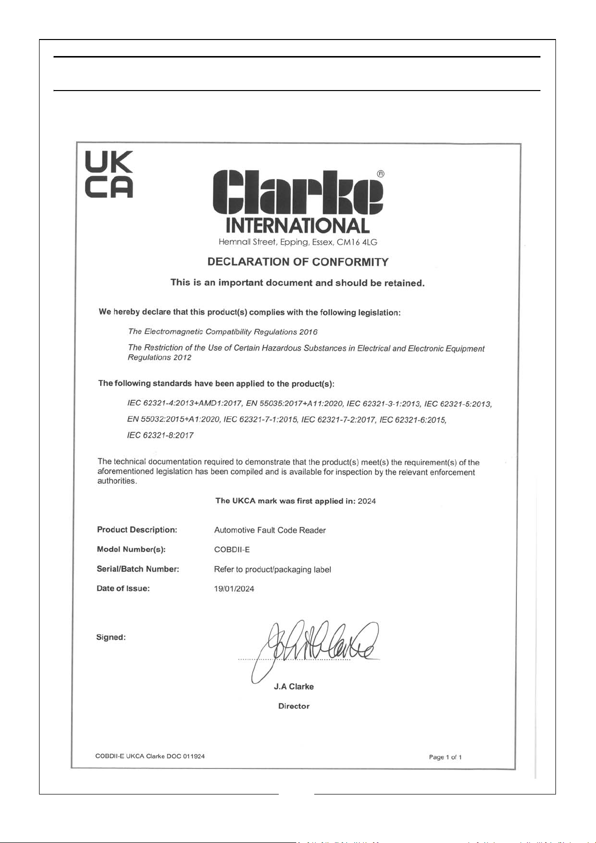
DECLARATION OF CONFORMITY - UKCA
42
Parts & Service: 020 8988 7400 / E-mail: [email protected] or [email protected]
Page 43

DECLARATION OF CONFORMITY - CE
43
Parts & Service: 020 8988 7400 / E-mail: [email protected] or [email protected]
Page 44

 Loading...