

Page 1
HYDRAULIC MOTOR CYCLE LIFT
Model: CML2
Part No: 7610142
OPERATING & MAINTENANCE
INSTRUCTIONS
1000
Page 2

2
11
Page 3
Thank you for purchasing this CLARKE Strongarm hydraulically operated Motor Cycle Lift.
Before attempting to use the lift, please read this leaflet thoroughly and follow the instructions
carefully. In doing so you will ensure the safety of yourself and that of others around you,
and you can also look forward to the lift giving you long and satisfactory service.
GUARANTEE
This CLARKE product is guaranteed against faulty manufacture for a period of 12 months
from the date of purchase. Please keep your receipt which will be required as proof of
purchase.
This guarantee is invalid if the product is found to have been abused or tampered with in
any way, or not used for the purpose for which it was intended.
Faulty goods should be returned to their place of purchase, no product can be returned to
CLARKE International without prior permission.
This guarantee does not effect your statutory rights.
SAFETY PRECAUTIONS
✘ NEVER exceed the lift’s capacity of 500kg, and use it ONLY for the purpose for which it
was intended.
IMPORTANT: If the load capacity decal becomes worn or illegible, contact Clarke
International Spare Parts Department, on 0208 988 7400 for replacement.
✘ NEVER use the lift if it has been subjected to an abnormal load or shock. It should be
removed from service immediately and fully inspected by qualified personnel, and
passed as serviceable, before being used again.
✘ NEVER rely upon the Hydraulic Ram (item 1), to support the Table. Always use the
Locking Bars (see Fig. 1) to secure the table in one of the positions provided.
✔ ALWAYS use the Lift on a solid, flat, level surface only.
✔ ALWAYS screw down the Stabilisers (see Fig. 6), before putting the platform under load.
NOTE: The castors are not designed to take the weight of a fully loaded platform, but are
used merely to move the lift quickly and easily around the workshop. On no account must
you raise a loaded platform unless the stabilisers are screwed down, and NEVER transport a
load using the lift.
✔ ALWAYS use appropriate safety equipment, such as protective footwear, when using
this lift.
✔ ALWAYS inspect the lift before use to ensure it is in good condition, and replace any
damaged or worn parts.
✔ ALWAYS use spare parts supplied by Clarke International. Using non-standard parts
could be extremely dangerous.
✔ ENSURE that the lift is properly maintained, and lubricated at all times, and that no rust
or other forms of corrosion is allowed to weaken any part of it.
✔ ENSURE the operator is skilled and trained in both operation and safety aspects.
10
3
Page 4
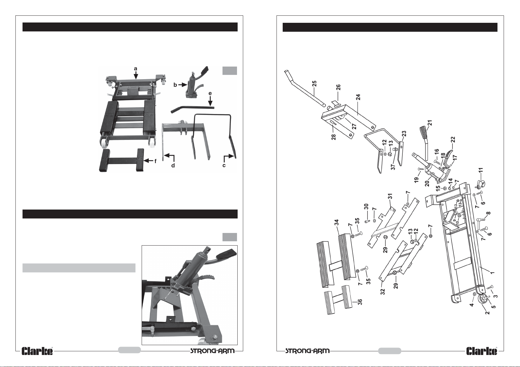
UNPACKING
Lay out the components carefully, and check to ensure that no damage has
occurred during transit. Any damage should be reported to your Clarke dealer
immediately.
Fig.1
Loose components comprise:
a. Base Assembly
b. Ram Assembly
c. Locking Bar
d. Frame
e. Handle
f. Loose Support
PARTS DIAGRAM
ASSEMBLY
1. The Ram Assembly.
First, secure the ram assembly to its
platform using the two bolts with nuts and
washers supplied, as shown in Fig. 1.
Tighten the nuts securely
Fig.2
4
9
Page 5
PARTS LIST
2. The Frame: Ref: Fig.3
No. Description Part No.
1. Base HTCML201
2. Wheel HTCML202
3. Bolt M8x65 HTCML203
4. Lock Nut M8 HTCML204
5. Bush HTCML205
6. Bolt Ml0x40 HTCML206
7. Washer HTCML207
8. Screw Ml2 HTCML208
9. Washer HTCML209
10. Nut M8 HTCML210
11. Caster Assembly HTCML211
12. Washer HTCML212
13. Lock Nut M10 HTCML213
14. Spring Washer HTCML214
15. Nut M12 HTCML215
16. Bolt M8x25 HTCML216
17. Pin HTCML217
18. Circlip HTCML218
19. Bolt M8xl0 HTCML219
No. Description Part No.
20. Jack HTCML220
21. Release Pedal HTCML221
22. Foot Pedal HTCML222
23. Locking Bar HTCML223
24. Frame HTCML224
25. Handle HTCML225
26. Clevis Pin HTCML226
27. Lock Pin HTCML227
28. Split Pin HTCML228
29. Lock Nut M12 HTCML229
30. Bolt Ml0x50 HTCML230
31. Back Strut HTCML231
32. Front Strut HTCML232
33. Bolt Ml2x60 HTCML233
34. Saddle HTCML234
35. Bolt Ml2 HTCML235
36. Loose Support HTCML236
37. Bush (1) HTCML237
Fig.3
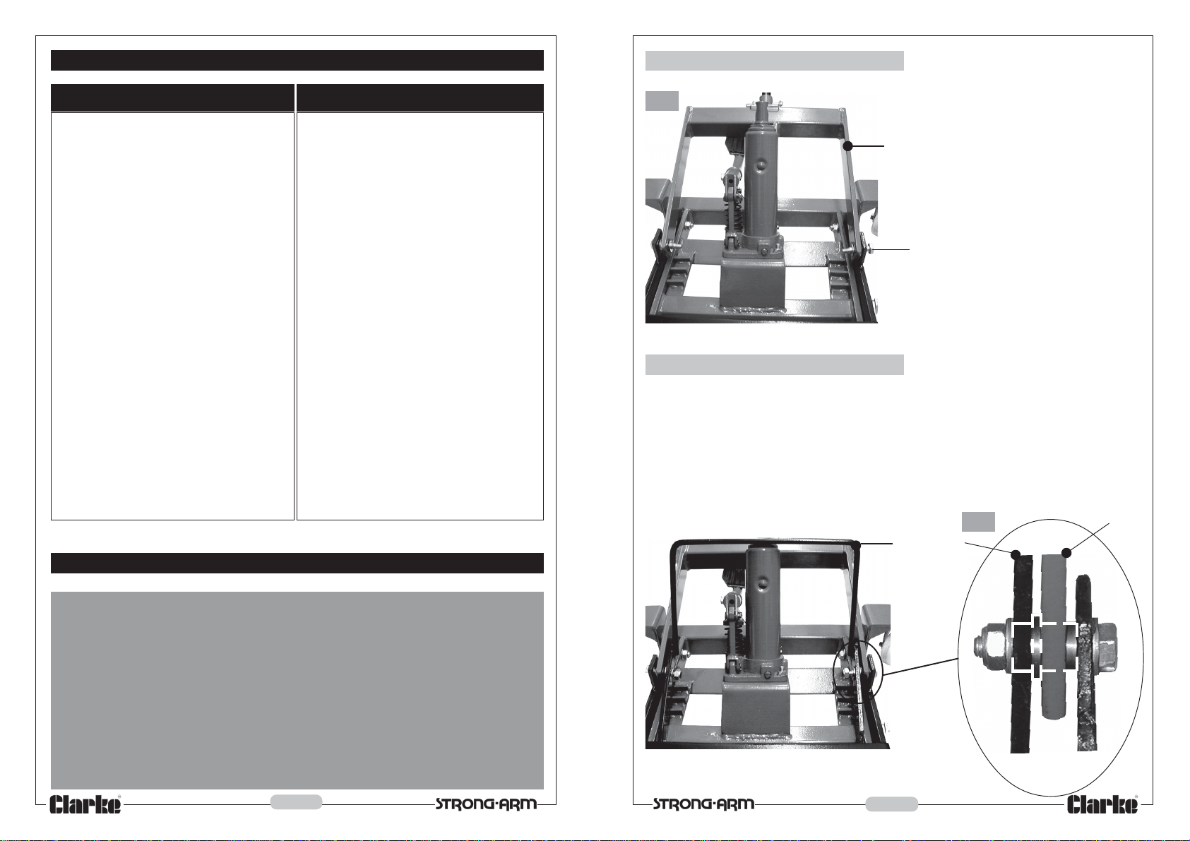
Frame
Remove the pin, securing the
ram to the frame, if fitted.
Place a flat washer on the
securing bolt (A), then thread
the bolt through the hole in the
base assembly bracket, and
have an assistant hold it in place.
Insert the collar (Shown in dotted
line in the insert, Fig.4), through
A
the hole in the end of the Frame,
long boss first, then thread the
collar, with frame, over the bolt.
Repeat this procedure on the
opposite side.
3. The Locking Bar: Ref: Fig.4
Locate the locking bar on to the collar at each side ( It will be necessary to ‘spring’
the bar in order to do so), then place a flat washer on to the threads of the bolt
and screw on the locknut. Tighten securely.
Ensure the Locking Bar is free to rotate under its own weight. It may be necessary
to manipulate the bar, or bend it, by hand slightly, in order to accomplish this.
The locking bar should rotate so that the ends engage in one of the slots in the
base, when the frame is raised.
Fig.4
Locking Bar
Frame
PARTS AND SERVICE CONTACTS
For Spare Parts and Service, please contact your nearest dealer, or CLARKE
International, on one of the following numbers.
PARTS & SERVICE TEL: 020 8988 7400
PARTS & SERVICE FAX: 020 8558 3622
or e-mail as follows:
PARTS: Parts@clarkeinternational.com
SERVICE: Service@clarkeinternational.com
8
Collar shown
in dotted line
5
Page 6
4. The Ram to Frame.
b. Lowering a Load
Line up the holes in the mounting bracket and ram, then locate the ram using the
pin previously removed and secure using the split pin provided.
NOTE: It may be necessary to push the ram into the cylinder, in order to line up the holes. To
do this, press down on the Release Pedal, (see Fig. 5), whilst levering the ram down using a
screwdriver, or similar tool.
5. The Handle
The handle is secured to the frame using the pin provided
6. The Loose Support
The loose support may be used at any time to provide stability for a load, and
simply rests in a convenient location on the saddle.
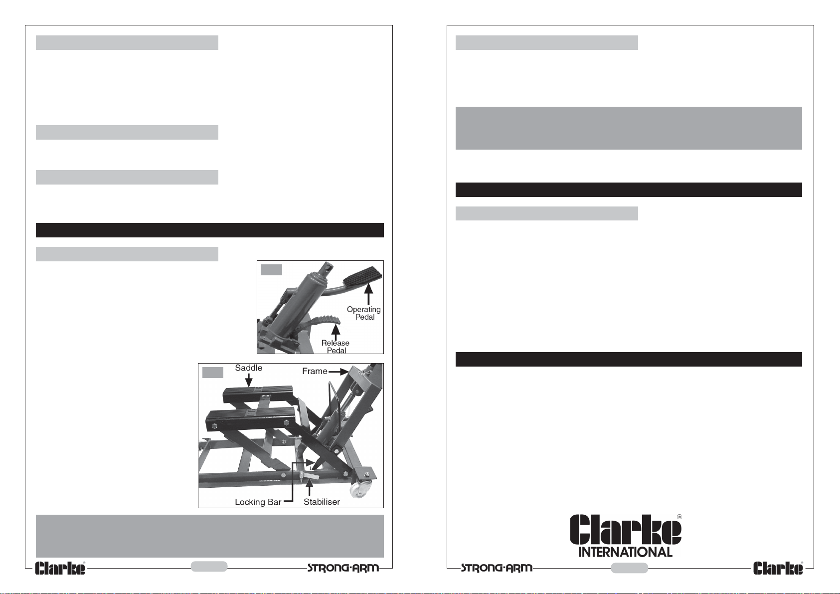
OPERATION
a. Raising a Load
Position the Lift so that the saddle is at right angles
to, and between the wheels of, the motor cycle,
and as near to the centre of gravity as possible.
Pump the Operating Pedal so that the saddle
makes light contact with the motor cycle frame,
then assess where packing is required in order
to raise the load in a fully stabilised manner . The
loose support may also be used for this purpose.
When satisfactorily supported,
screw down the two stabilisers (see
Fig. 6), to remove any load from
the castors, then raise the load by
pumping the Operating Pedal.
Once you have attained the
desired height, ensure the Locking
Bar is engaged with one of the pair
of slots in the base, then press the
Release Pedal gently, allowing the
saddle to lower until the load is
taken by the Locking Bar.
It is now safe for you to commence
work.
1. UNDER NO CIRCUMSTANCES must you rely upon the ram to support the load.
2. Ensure the Motor cycle is fully stabilised before commencing work
Fig.6
WARNING!
Fig.5
When work is complete, pump the Operating Pedal in order to raise the load
slightly and release the Locking Bar. Once the bar is released, hold it, to pr event
it dropping back into one of the slots, then very gently press down on the Release
Pedal and allow the load to descend.
WARNING!
Take great care when lowering. A light touch ONLY is required. Too heavy a
touch will result in the load descending too rapidly which could be hazardous
MAINTENANCE
Before each use
Visually inspect the lift for distortion of parts, cracked welds, damaged wheels or
castors, excessive oil leak from ram, or any other sign of damage. Should any of
these be apparent, remove the Lift from service, and have it inspected and
repaired by a qualified technician before putting back into use. If necessary,
consult your Clarke dealer.
If the Warning label becomes worn or illegible, have it replaced. Contact your
Clarke dealer.
SPECIFICATIONS
Model Number ..........................................................CML2
Part Number ..............................................................7610142
Maximum Load .........................................................500kg
Minimum Height ........................................................ 105mm
Maximum Height .......................................................472mm
Weight ........................................................................45kg
6
7
 Loading...