

Page 1
OPERATING & MAINTENANCE
INSTRUCTIONS
Model No. CLS400
PART NO: 3401990
GC10/11
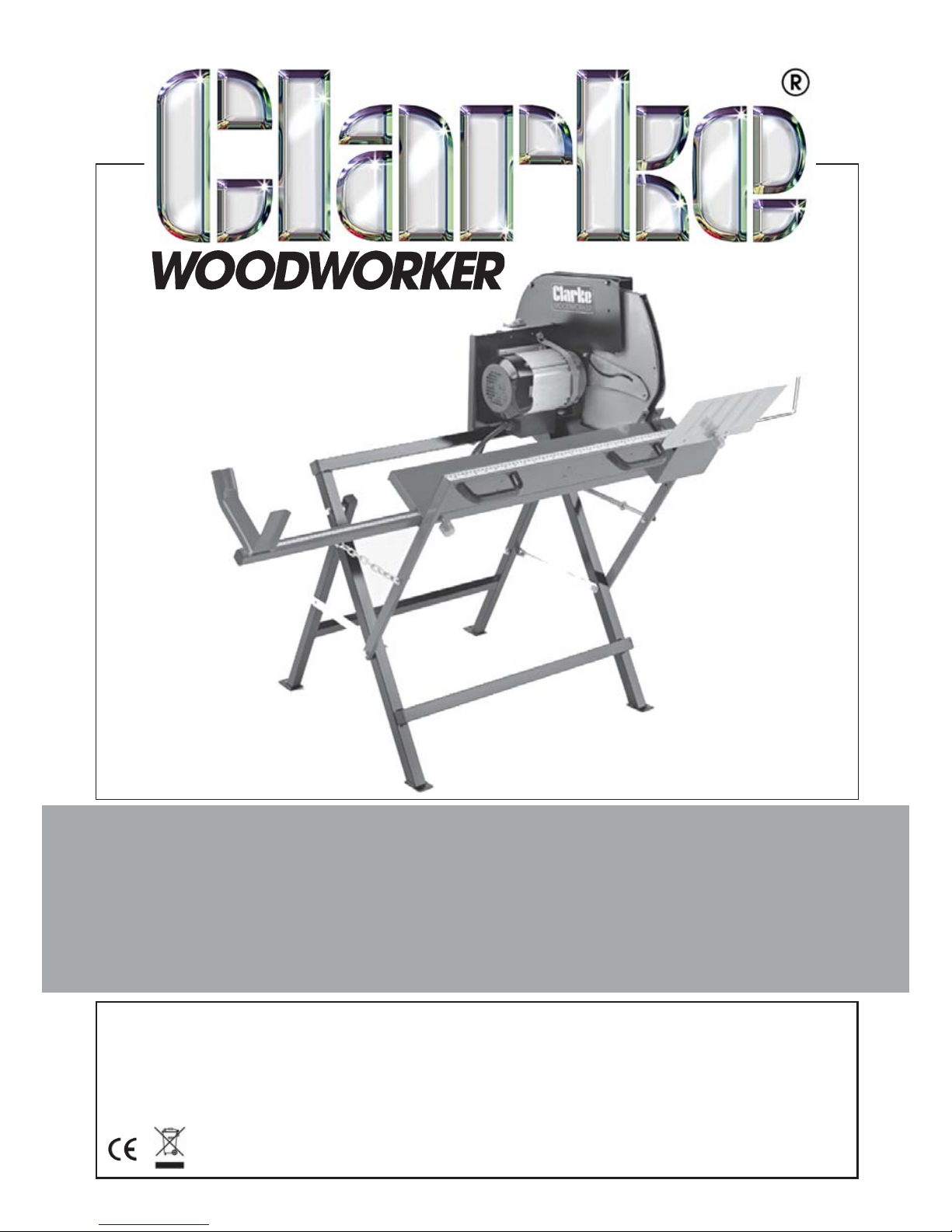
400MM LOG SAW
Page 2
2
Parts & Service: 020 8988 7400/E-mail:[email protected] or [email protected]
INTRODUCTION
Thank you for purchasing this CLARKE Log Saw.
The CLARKE CLS400 is a single speed circular saw directly driven by the motor.
It is equipped with a log cradle which holds the log steady while working and
a hinged guard which retracts as the log is pushed against the saw.
When unpacking, check for damage or shortages etc. Any found should be
reported to your CLARKE dealer where the product was originally purchased.
Before attempting to use this product, please read this manual thoroughly
and follow the instructions carefully. In doing so you will ensure the safety of
yourself and that of others around you, and you can look forward to your
purchase giving you long and satisfactory service.
ENVIRONMENTAL PROTECTION
Do not dispose of this product or any worn out blades with general
household waste. It must be disposed of according to the laws
governing Waste Electrical and Electronic Equipment at a recognised
disposal facility.
GUARANTEE
This product is guaranteed against faulty manufacture for a period of 12
months from the date of purchase. Please keep your receipt which will be
required as proof of purchase.
This guarantee is invalid if the product is found to have been abused or
tampered with in any way, or not used for its intended purpose.
Faulty goods should be returned to their place of purchase, no product can
be returned to us without prior permission. This guarantee does not effect
your statutory rights.
Page 3

3
Parts & Service: 020 8988 7400/E-mail:[email protected] or [email protected]
GENERAL SAFETY RULES
WORK AREA
1. Keep the work area clean and well lit. Cluttered and dark areas invite
accidents.
2. Do not operate power tools in explosive atmospheres such as in the
presence of flammable liquids, gasses or dust. Power tools create sparks
which may ignite dust or fumes.
3. Keep children and bystanders away while operating any power tool.
Distractions can cause you to lose control.
ELECTRICAL SAFETY
1. Power tools must match the power outlet. Never modify the plug in any
way. Do not use adaptor plugs with earthed (grounded) power tools.
Correct plugs and outlets will reduce the risk of electric shock.
2. Do not expose power tools to rain or wet conditions. Any water entering
power tools will increase the risk of electric shock.
3. Do not abuse the electrical cable. Never use the cable for pulling or
unplugging the power tool. Keep the cable away from sources of heat, oil,
sharp edges or moving parts. Damaged or tangled cables increase the
risk of electric shock.
4. Use outdoor extension leads. If working outdoors, always use an approved
cable extension suitable for the power rating of this tool (see
specifications), the conductor size should also be at least the same size as
that on the machine, or larger. When using a cable reel, always unwind
the cable completely. We strongly recommend that this machine is
connected to the mains supply via a Residual Current Device (RCD).
PERSONAL SAFETY
1. Stay alert, watch what you are doing and use common sense when you
are operating a power tool. Do not operate a power tool when you are
tired, ill or under the influence of alcohol, drugs or medication.
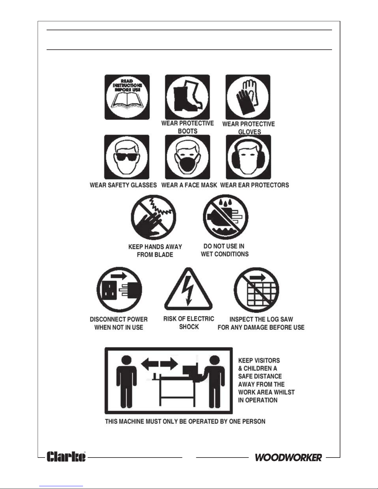
2. Wear personal protective equipment including eye protection. Safety
equipment such as a dust mask, non-skid shoes or hearing protection used
for appropriate conditions will reduce personal injuries. Use a face or dust
mask if operation is particularly dusty. Wear ear protectors/defenders as
the noise level of this machine can exceed 85dB (A).
3. Do not over-reach. Keep your proper footing and balance at all times. This
enables better control of the power tool in unexpected situations.
4. Concentrate on the job in hand, no matter how trivial it may seem. Be
aware that accidents are caused by carelessness due to familiarity.
Page 4

4
Parts & Service: 020 8988 7400/E-mail:[email protected] or [email protected]
5. Avoid accidental starting of the machine. Ensure the switch is in the off
position before plugging the machine in to the power supply. Plugging in
power tools that are switched on invites accidents.
6. Dress properly. Do not wear loose clothing or jewellery which may get
caught in moving parts. Wear protective hair covering to contain long
hair. For best footing, wear rubber soled footwear. Keep floor clear of oil,
scrap wood, etc.
7. Wear gloves while handling saw blades and always store them in the
protective packing provided. A dust mask should be warn to reduce the
inhalation of harmful dust.
8. Always remove and stack cut timber in a suitable place, away from the
operator.
9. Switch the machine OFF immediately after the task is completed.
POWER TOOL USE AND CARE
1. Do not force the machine. Use the correct tool for your application. It will
do a better and safer job at the rate for which it was designed.
2. Do not use the power tool if the switch does not turn it on and off. Any
power tool that cannot be controlled with the switch is dangerous and
must be repaired.
3. Disconnect the power tool from the power supply before making any
adjustments or storing the tool. These measures will reduce the risk of the
power tool starting accidentally.
4. Store power tools out of the reach of children and do not allow persons
unfamiliar with these instructions to operate this product. Power tools are
potentially dangerous in the hands of untrained users.
5. Maintain power tools in top condition. Keep machines clean for the best
and safest performance. Check for misalignment or binding of moving
parts, broken parts, or any condition that may affect the tool’s operation.
If damaged, have the tool repaired before use. Many accidents are
caused by poorly maintained power tools.
6. Machine cleanliness. Do not allow the ventilation slots in the motor to
become blocked with dust.
7. Check the power tool for damage before use. Any damaged part should
be inspected to ensure that it will operate properly and perform its
intended function. Any damage should be properly repaired or the part
replaced. If in doubt, DO NOT use the machine. Consult your local dealer.
SERVICING
1. When necessary, have your power tools serviced or repaired by a
qualified person using identical replacement parts. This will ensure that the
safety of the power tool is maintained.
Page 5

5
Parts & Service: 020 8988 7400/E-mail:[email protected] or [email protected]
PRECAUTIONS SPECIFIC TO CIRCULAR SAWS
1. ALWAYS wear ear protectors/defenders during continuous use as the noise
level of this machine can exceed 85dB (A).
2. ALWAYS keep the mains cable well away from the saw and ensure an
adequate electrical supply is close at hand so that the operation is not
restricted by the length of the cable.
3. ALWAYS use only the correct blade for this saw and ensure the blade is
fully tightened before use. The blade must always be rated to operate at
a rotational speed equal to, or greater than that of the machine.
4. Beware of foreign objects. When cutting pre-used wood, ensure all nails
have been removed beforehand. Nails will damage the saw blade.
5. Switching off. Remember that the blade will continue to rotate for a short
time after the stop button has been pressed to stop the saw.
6. NEVER operate the saw when the moving blade guard is not working
properly. The guard should be checked for correct operation before
each use. It must move freely and readily return to the starting position.
7. NEVER operate the saw without the removable blade guard being
installed correctly.
8. NEVER start the saw when the blade is in contact with the work.
9. DO NOT use the saw if the power cable, plug or motor is in poor condition.
10. ALWAYS hold the workpiece securely when cutting. The workpiece should
always be placed securely in the log cradle to avoid loss of control.
11. ALWAYS hold the cradle handles with both hands to keep hands well away
from the saw blade.
12. Do not attempt to saw very small logs including those which cannot be
properly secured.
CHANGING BLADES
1. Unplug the saw from the power supply before changing blades, and take
care to prevent entrapment of the fingers between the blade and the
inner guard. Ensure the blade is secure before use.
2. Use the appropriate saw blade for this saw. Correct blades are available
from your Clarke dealer, (part number 3401992).
3. Only use saw blades in good working condition. Discard and replace
cracked or bent saw blades.
Please keep these instructions in a safe place for future reference.
Page 6
Page 7
7
Parts & Service: 020 8988 7400/E-mail:[email protected] or [email protected]
ELECTRICAL CONNECTIONS
WARNING! Read these electrical safety instructions thoroughly
before connecting the product to the mains supply.
Before switching the machine on, make sure that the voltage of your
electricity supply is the same as that indicated on the rating plate. This
product is designed to operate using 230 VAC mains power. Connecting it to
any other power source may cause damage.
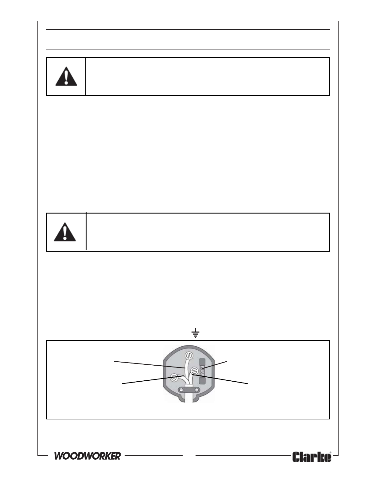
This product may be fitted with a non-rewireable plug. If it is necessary to
change the fuse in the plug, the fuse cover must be refitted. If the fuse cover
becomes lost or damaged, the plug must not be used until a suitable
replacement is obtained.
If the plug has to be changed because it is not suitable for your socket, or
due to damage, it should be cut off and a replacement fitted, following the
wiring instructions shown below. The old plug must be disposed of safely, as
insertion into a mains socket could cause an electrical hazard.
WARNING! The wires in the power cable of this product are
coloured in accordance with the following code:
Blue = Neutral Brown = Live Yellow and Green = Earth
If the colours of the wires in the power cable of this product do not
correspond with the terminal markings of your plug, proceed as follows.
• The wire which is coloured Blue must be connected to the terminal
which is marked N or coloured Black.
• The wire which is coloured Brown must be connected to the
terminal which is marked L or coloured Red.
• The wire which is coloured Yellow and Green must be connected to
the terminal which is marked E or or coloured Green.
Plug must be BS1363/A approved
Earth Always fit a 13 Amp fuse.
(Green and Yellow)
Neutral Live
(Blue) (Brown)
Ensure that the outer sheath of the cable is firmly held by the clamp
We strongly recommend that this machine is connected to the mains supply
via a Residual Current Device (RCD).
If in doubt, consult a qualified electrician. DO NOT attempt repairs yourself.
Page 8
8
Parts & Service: 020 8988 7400/E-mail:[email protected] or [email protected]
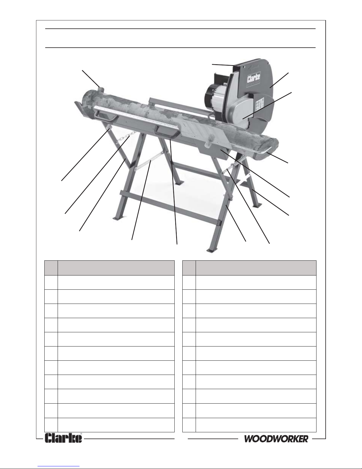
oN metI oN metI
1ekoYtroppuSgoL21eldarCylbmessAtroppuS
2dnatStroppuS31niahCgnitcennoC
3drauGdexiF41)2x(bonKgniruceS
4drauGelbav
omeR xobehtnideilppusstraprehtO
5)seceip2(drauG)gnivoM(rennI*tekcarBgnicrofnieR
6raBpotSgoL*edalBwaS
7etalPevitc
etorP*)2x(scsidgnirucesedalB
8ylbmessAgnirpSnruteR*hcnerWnepO
9)dehcattarotomhtiw(dnatSrotoM*hcnerWgnikcoLedalB
01)2x(eldnaH*
)detcennoc(hctiwSFFO/NO
11)2x(etalPgnitcennoC*ediuGgnidilS
OVERVIEW
1
2
3
4
5
6
7
8
910
11
12
13
14
Page 9
9
Parts & Service: 020 8988 7400/E-mail:[email protected] or [email protected]
ASSEMBLY
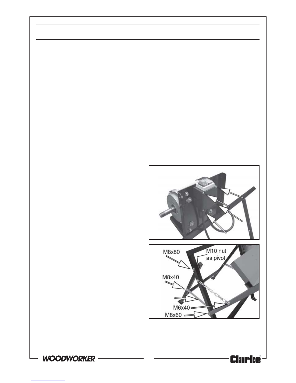
ASSEMBLING THE SWITCH, MOTOR STAND, SUPPORT STAND &
CRADLE SUPPORT ASSEMBLY
FIXINGS REQUIRED:
ON/OFF Switch;- 4 x M4 x 55 mm screws & 4 x M4 washers
Motor Stand/Support Stand;- 2 x M8 x 80 bolts, 4 x 8 mm washers, 2 x M8
locknuts & 2 x M10 nuts
Cradle Support;- 2 x M8 x 60 bolts, 2 x M8 locknuts & 2 x 8 mm washers
Connecting Plates;-2 x M8 x 40 bolts, 2 x M8 locknuts, 8 x 8 mm washers
Return Spring Assembly;- 2 x M6 x 40 bolts, 2 x M6 locknuts 3 x 6 mm
washers & 1 x M8 nut
Connecting Chain;- 2 x M6 x 40bolts, 2 M6 nuts & 4 x M6 washers
Refer to the ‘Overview’ illustration
and to Figs 1- 3.
1. Mount the ON/OFF switch to the
Motor Stand using the 4 x M4 x 55
mm screws with washers as shown
in Fig 1.
2. Bolt the Motor Stand and Support
Stand together using 2 x M8 x 80
bolts with nuts & washers. Insert a
single M10 nut each end to act as
a bearing between both stands.
3. Join the Cradle Support Assembly
to the Motor Stand using M8 x 60
bolts. At the same time attach the
Connecting Plates as shown, with
the same fastenings.
4. Join the Connecting Plates to the
Motor Stand, using the M8 x 40
bolts, flat washers and M8
locknuts.
Fig 1
Fig 2
Connecting
Plate
Page 10
10
Parts & Service: 020 8988 7400/E-mail:[email protected] or [email protected]
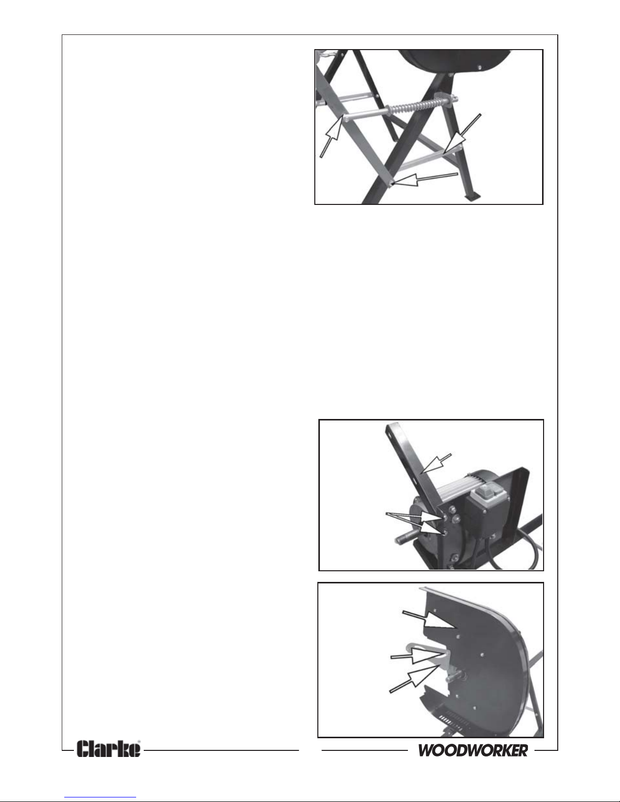
5. Connect the Cradle Support
Assembly to the Motor Stand using
the Connecting Chain at one
end and the Return Spring
Assembly at the end nearest to
the saw blade. Use the M6x40
bolts as shown, including a single
M8 locknut and additional
washers for the pivot between the
Return Spring Assembly and the
Cradle Support.
INSTALLING THE FIXED GUARD, MOVING GUARD & GUIDE PLATE
FIXINGS REQUIRED:
Reinforcing Bracket;- 2 x M8 x 15 Bolts, 2 x 8 mm Washers & 2 x M8
Locknuts
Fixed Guard;-1 x M8 x 35 X-head bolt, 1 x M8 x 15 x-head bolt, 1 x 15 x
M8 Hex bolt 3 x Washer 8mm & 3 x M8 Locknuts & 2 x M6 x15 Hex
bolts, 2x Washer 6mm & 2 x M6 Locknuts
Sliding Guide;- 1 x M5 Special Bolt, 1 x M5 x 8 Bolt, 2 x M5 Locknuts & 2
x M5 Washers
Log Cradle/Guard;- 4 x M6 x 12 Socket Head Screws
Moving Guard;- 2 x X-head screws
1. Attach the Reinforcing Bracket to
the motor mounting plate using 2
x M8 bolts as shown in Fig 4.
2. Secure the Fixed Guard to the
Motor Stand with the bolts, flat
washers and locknuts itemised
above. At the same time, bolt the
guard to the Reinforcing Bracket
with 3 further bolts, nuts & washers.
3. Fit the Sliding Guide to the Fixed
Guard as shown in Fig 5 using the
special M5 x 8 bolt, nut & washer.
4. Take one half of the Moving Guard
and bolt it to the Sliding Guide
using an M5 x 8 bolt, nut & washer,
inserting a loose M6 nut supplied
as a bearing between the guard
and the guide. When tightening
this bolt, ensure the guard and
guide are able to hinge freely.
Fig 5
Fixed Guard
Guide
Plate
Special
M5 bolt
Fig 4
Reinforcing
Bracket
Securing
Bolts
M8 nut
as pivot
Fig 3
Connecting
Plate
M6 x40
bolt
Page 11
11
Parts & Service: 020 8988 7400/E-mail:[email protected] or [email protected]
5. Connect the two halves of the
Moving Guard together using the
two short machine screws
together with the flat and spring
washer which should be found
already fitted to one half of the
guard.
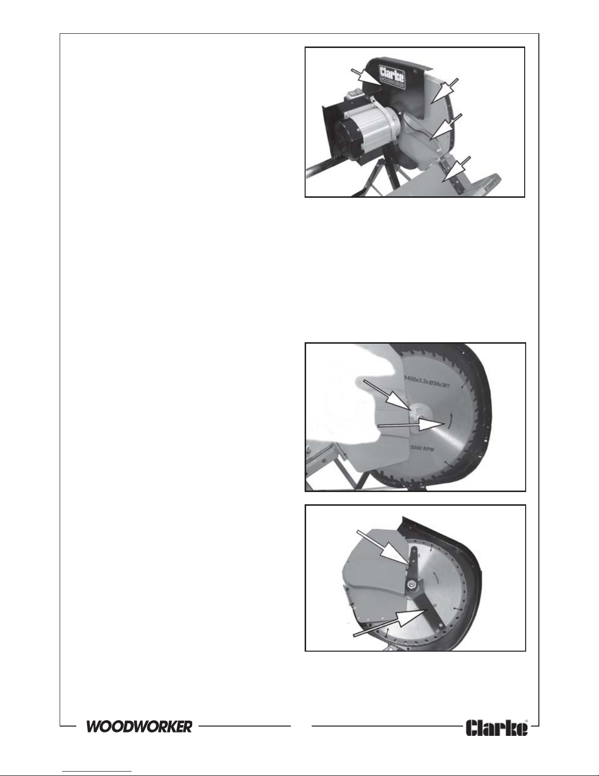
6. Lift up the Log Cradle and attach
the Moving Guard to it with 4 x M6
x 12 socket headed screws as
shown in Fig 6. Check that the
Log Cradle and Moving Guard hinge freely.
INSTALLING THE SAW BLADE
FIXINGS REQUIRED:
1 x M20 Nut
1 x M20 Flat Washer
4 x M6 x 45 Bolts with locknuts (attached to the Removable Guard)
1. Install the inner Retaining Disc,
saw blade and outer Retaining
Disc on the motor shaft and
secure them with the flat washer
and 30 mm nut.
• Install the blade in the orientation
shown in fig 7. Do not use a blade
with no markings, but if they have
become worn away during
previous use, inspect the blade
and note the position of the
cutting teeth. The teeth must face
in the direction of rotation as
shown when viewed from the
exposed side.
• Never use cracked, blunt or
otherwise damaged blades.
• Ensure that the blade used is
rated at least equal to the speed/
performance of the machine.
Note that the blade is designed to
sit on a machined shoulder on the
drive shaft and must be in this position before the securing nut is tightened.
2. Use the Blade Locking Wrench to stop the blade from turning while
tightening the nut with the open wrench provided as shown in Fig 8.
Fixed
Guard
Moving
Guard
Guide
Plate
Fig 6
Log
Cradle
Fig 8Open Wrench
Blade
Locking
Wrench
Correct
direction
of rotation
Outer
Retaining Disc
Fig 7
Page 12
12
Parts & Service: 020 8988 7400/E-mail:[email protected] or [email protected]
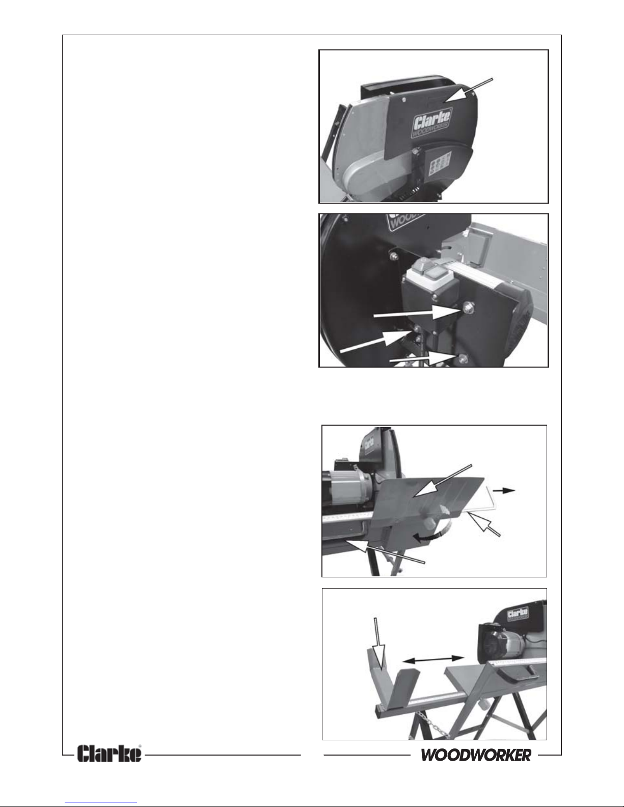
3. Turn the blade gently by hand
and check it is passing cleanly
through the gap in the cradle
without touching.
If not correct, the blade can be
correctly aligned by loosening the
four bolts holding the motor to the
motor support plate (shown in fig
10), and adjusting the motor in the
desired direction.
• Locknuts are used to retain the
fixing bolts permanently to the
Removable Guard.
3. Attach the Removable Guard
using the M6 x 45 mm bolts (these
should be secured to the guard
by locknuts as shown, to prevent
their possible loss). Screw the bolts
into the fixing nuts welded to the
fixed guard.
INSTALLING THE HANDLES, PROTECTIVE PLATE & SUPPORT YOKE
FIXINGS REQUIRED:
Handles;- 4 x M5 x10 hex headed
screws
Protective Plate;-2 x M6 x 8
machine screws
1. Secure both the handles to the log
cradle with M6x10 hex headed
screws.
2. Attach the Protective Plate using 2
x M6 machine screws.
3. Insert the Log Support Yoke into
the cradle and position it as
required with the securing knob.
Slide in the Log Stop Bar into the
other end of the cradle and set it
in position as required by screwing
in the securing knob as shown on
page 13.
Removable
Guard
Fig 9
Adjustable
Bolts
Fig 10
Support Yoke
Fig 12
Log Stop Bar
Handle
Protective
Plate
Fig 11
Page 13
13
Parts & Service: 020 8988 7400/E-mail:[email protected] or [email protected]
OPERATION
BEFORE STARTING WORK
WARNING! THIS SAW SHOULD NOT BE USED BY ANYONE NOT FAMILIAR
WITH ITS OPERATION.
1. Check that all component parts are secure. If the log saw is not fixed to
the floor, ensure that it is placed in a steady position on firm ground.
2. Ensure the power cable is well away from the saw and the workpiece,
then plug into the mains supply.
3. Always check that the saw guard and cradle move freely and spring
back instantly when released.
4. Check that any previously used timber being sawn does not contain any
nails or other metal objects which would damage the blade.
IMPORTANT: DO NOT plug in to the mains, unless you have ensured the
saw is switched OFF and the removable guard is in place.
Note; the maximum log diameter that can be cut is 125mm.
USING THE SAW
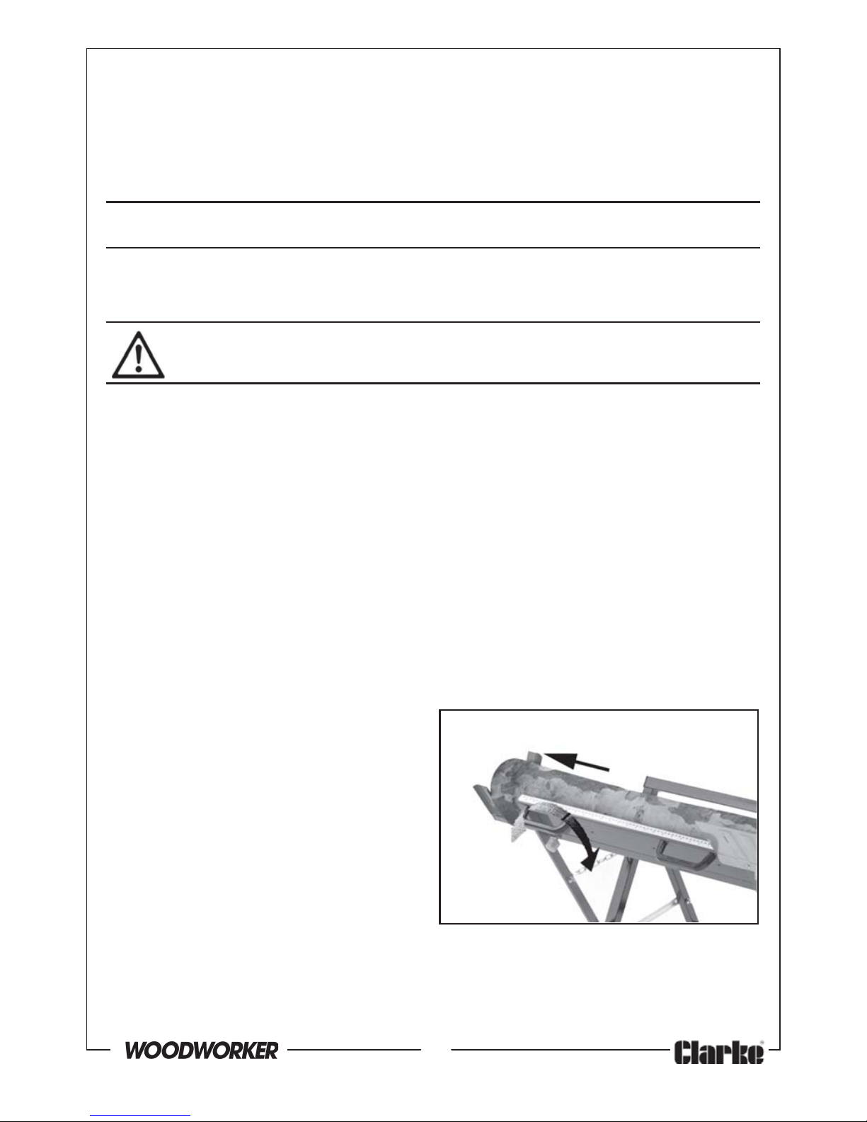
1. Position the workpiece in the
cradle so that it will not move
while cutting.
2. If the length of the log is greater
than the length of the cradle,
extend the log support yoke and
set it’s position to suit with the
securing knob.
3. If logs of equal length are
required, set the log stop bar to
the required distance. Measure
this against the scale on the cradle and lock in position with the securing
knob.
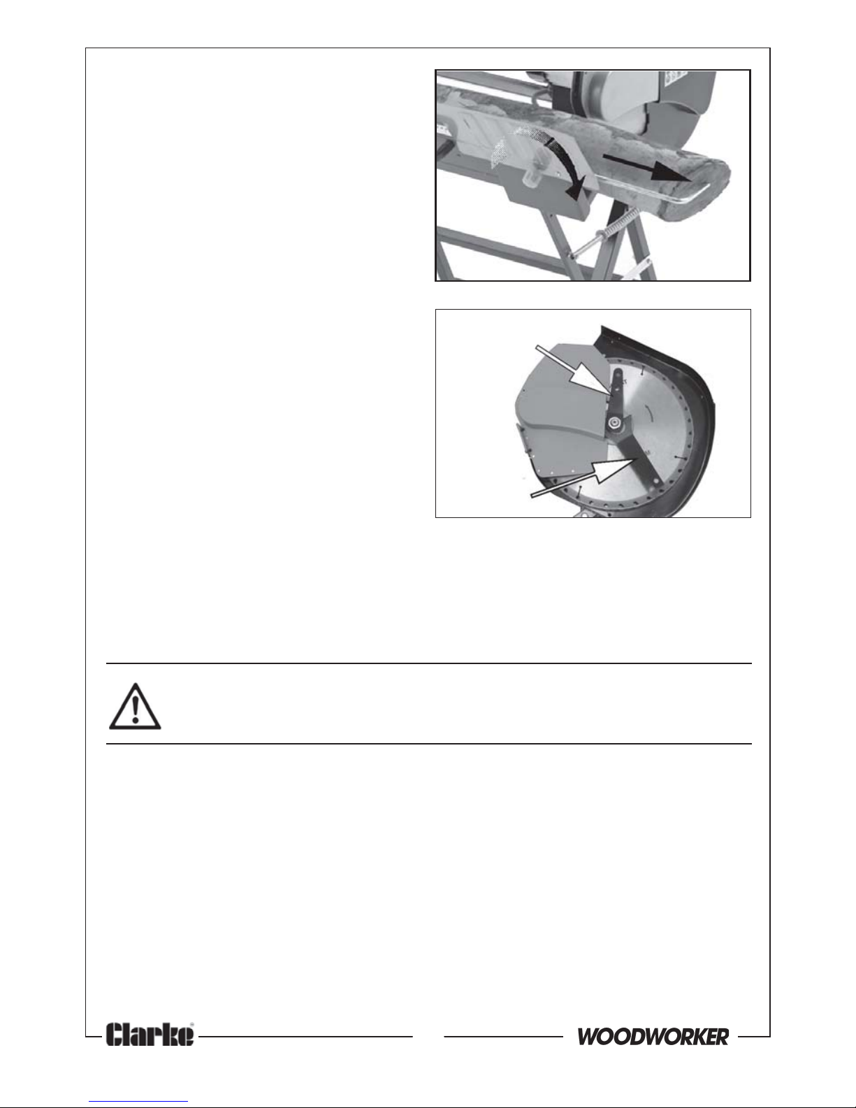
4. Switch the saw on and hold both handles at all times to push the
workpiece steadily against the saw. Wait for the motor to reach full speed
MOUNTING THE SAW TO THE FLOOR
The foot of each leg is provided with a bolt hole for fixing the log saw to a
suitably level floor or platform. Choose a suitable position close to a
convenient power supply and bolt or screw the stand securely in position.
(fixings not supplied).
Support Yoke
Securing
Knob
Fig 13
Page 14
14
Parts & Service: 020 8988 7400/E-mail:[email protected] or [email protected]
before cutting. Take care not to
let the log bounce against the
saw blade. Always remove the
sawn wood before attemping to
cut the next piece.
5. Regardless of the diameter of the
wood, only one piece should be
placed on the cradle for cutting
at any one time. Do not attempt
to saw multiple pieces at once.
• Always control the cradle
keeping both hands on the
handles provided. When pushing
the wood into the saw, take care
that the motor speed does not
drop.
6. To stop the saw press the OFF
switch. Always switch off before
unplugging and never leave the
saw running unattended.
7. Avoid putting unnecessary
pressure on the blade and avoid
applying lateral pressure. Let the blade work naturally.
• Never try to re-start the saw if the blade becomes jammed in the
workpiece.
CHANGING BLADES
CAUTION: ONLY USE SAW BLADES WITH THE CORRECT FITTING AS
SUPPLIED. ALWAYS ENSURE THE SAW IS DISCONNECTED FROM THE
POWER SUPPLY BEFORE INSTALLING/REMOVING THE BLADE.
1. Ensure the power cable is disconnected from the power supply. Take care
that the saw blade has cooled down before touching if it has just been in
use.
2. Take off the removable guard by undoing the 4 bolts.
3. Use the blade locking wrench to prevent the blade from turning and
remove the blade retaining nut using the open wrench provided.
4. Remove the washer and outer retaining disc, and remove the blade while
deflecting the inner guard by hand. Brush away any dust or debris from
the spindle before fitting the new blade.
5. Replace in reverse order, ensuring the blade is fitted the right way round
and that the retaining nut is secure. Use the blade locking wrench to stop
the blade from turning while tightening the nut with the open wrench.
Blade
Locking
Wrench
Open Wrench
Securing
Knob
Stop
Bar
Fig 14
Fig 15
Page 15
15
Parts & Service: 020 8988 7400/E-mail:[email protected] or [email protected]
CAUTION; INSTALLING THE BLADE THE WRONG WAY ROUND MAY
RESULT IN DAMAGE TO THE BLADE. SEE PAGE 11.
Note: Replacement blades are available from your CLARKE dealer;
Part No 3401992.
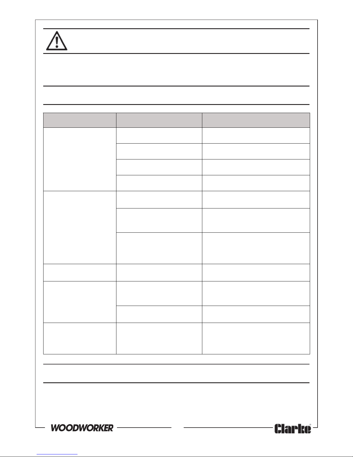
FAULT FINDING
melborP esuaCelbissoP ydemeR
tonlliwenihcaM
.etarepo
.ylppusrewopoN.yfitcerdnaylppuskcehC
.ytluafsihctiwS.relaedekralCruoytlusnoC
.nwolbsahgulpniesuF.ecalperdnakcehC
.ytluafsirotoM.relaedekralCruoytlusnoC
.tohsemocebrotoM.esuyvaehyludnUe
htotdeilppaecrofehtecudeR
.krowehtodlootehtteL.was
emocebevahstnevriA
.dekcolb
gnisustnevriaehttuonaelC
ah
tiwnaelcroriadesserpmoc
.htolcyrd
.egatlovylppuswoL.tcerrocsiegatlovylppuserusnE
,desusielbacnoisnetxenaf
I
gnitartcerrocehtfositierusne
.dnuownuyllufsidna
lanretniyvaeH
gnikraps
nrowsahcustluafrotoM
.sehsurb
rofre
laedekralCruoyotnruteR
.riaper
.noitarbivevissecxEdetnuomtonedalB
.yltcerroc
dnaedalbfognitaeskcehC
gniniat
erfossenthgitdnascsid
.tun
sgniraebrotomenihcaM
.nrow
rofrelaedekralCruoyotnruteR
.luahrevo
tucehtnosnruB
.r
ebmit
wastnulbrotcerrocnI
noesooledalB.edalb
.gnitnuom
ekralCgnisuedalbecalpeR
.tnemecalperdednemmocer
saed
albnethgitdnakcehC
.yrassecen
MAINTENANCE
Always inspect the saw before use and ensure it is in top condition.
Ensure that the guard can spring freely back to its closed position and clean
out any debris lodged behind it.
Page 16
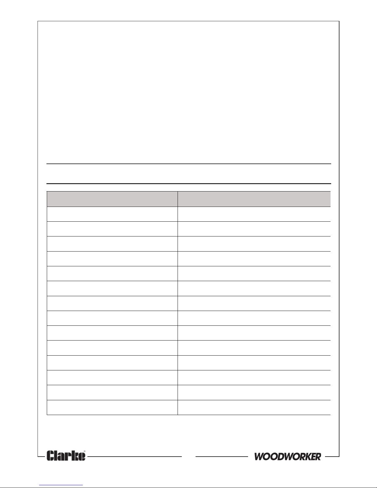
16
Parts & Service: 020 8988 7400/E-mail:[email protected] or [email protected]
metI noitacificepS
thgieWtcudorPgk53
)HxDxW(snoisnemiDmm5401x578x849
egatloVgnitarepOzH05/V032
gnitaResuFA31
rewoPr
otoMW0051
ssalCnoitalusnItcudorP1
deepSedalBdaol-oNmpr0082
htdiWgnittuCmumixaMmm521
retemaiDedalBmm004
ssenkcih
TedalBmm2.3
retemaiDeroBlanretnImm03
hteeTwaSfooN63
leveLerusserPdnuoSL
AP
)A(Bd98
leveLrewoPdnuoSdeetnarauGL
AW
)A(Bd401
SPECIFICATION
Please note that the details and specifications contained herein, are correct
at the time of going to print. However, CLARKE International reserve the right
to change specifications at any time without prior notice.
Check the power cable to ensure it is sound and free from cracks, bare wires
etc. Avoid using solvents when cleaning plastic parts, most plastics are
susceptible to damage from various types of commercial solvents.
After use, clean all dust and wood chippings from the saw and its hinged
parts and guards.
• Ensure motor air vents are clear of debris, (use compressed air to
clean the machine if possible).
For any problems requiring the dismantling and overhaul of the saw, contact
your CLARKE International Service Department on 020-8988-7400.
STORAGE
Store in a clean, dry environment protected from the weather and away
from children and untrained users.
Page 17
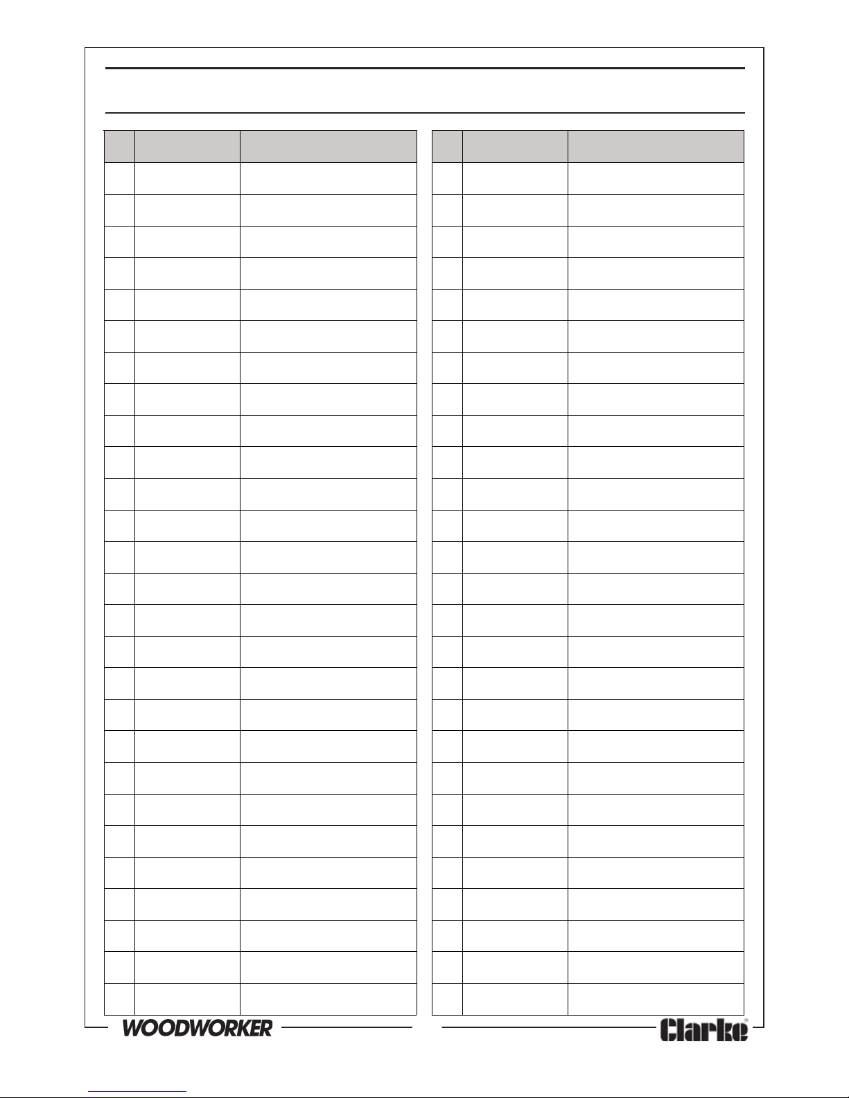
17
Parts & Service: 020 8988 7400/E-mail:[email protected] or [email protected]
oN oNtraP noitpircseD oN oNtraP noitpircseD
110004SLCHYhctiwSFFO/NO6262004SLCHY06x8MtloBdHtekcoS
220004SLCHYmm55x4MwercS7272004SLCHYetalPgnixiF
330
004SLCHYmm8x5MwercS8282004SLCHY04x6MtloBdHtekcoS
440004SLCHYdrauGedalBdexiF9292004SLCHY6MtunkcoL
550004SLCHYcsiDgn
iniateRrennI0303004SLCHYmm6rehsaWtalF
629910432.2x004edalBwaS1313004SLCHY21x6MwercSdaeh/R
770004SLCHYcsiDgniniate
RretuO2323004SLCHYetalPevitcetorP
880004SLCHYaid02rehsaWtalF3333004SLCHY6MbonKwercS
990004SLCHY02MtuN4343004SLCHY8x6
MwercSdaeH-X
0101004SLCHYdrauGelbavomeR5353004SLCHYdnatStroppuS
1111004SLCHYetalPediuGgnidilS6363004SLCHYeldnaH
212
1004SLCHY51x5MwercS7373004SLCHY54x6MwercStekcoS
3131004SLCHYaid5rehsaWtalF8383004SLCHYdnatStroppuSeldarC
4141004S
LCHY5MtunkcoL9393004SLCHYekoYtroppuSgoL
5151004SLCHY6MtuN0404004SLCHYniahCgnitcennoC
6161004SLCHY)HL(drauGgnivoM1414
004SLCHY01MtuN
7171004SLCHY)HR(drauGgnivoM2424004SLCHYyssAdnatSrotoM
8181004SLCHYmm8rehsaWtalF3434004SLCHY)llamS(p
aCdnE
9191004SLCHY8MtunkcoL4444004SLCHY)egraL(paCdnE
0202004SLCHY08x8MtloBdHtekcoS5454004SLCHYrotoM
1212004SLCHYtloB
ediuGlaicepS6464004SLCHY02x8MtloB
2222004SLCHYtekcarB7474004SLCHY8rehsaWtalF
3232004SLCHYgnirpS8484004SLCHY53x8MtloB
4242004SLCHYraBgnirpS9494004SLCHY51x8MtloB
5252004SLCHYraBpotSgoL0505004SLCHY51x6MwercSdaeH-X
1515004SLCHYtekcarBgn
icrofnieR
#25004SLCHYhcnerWnepO#35004SLCHYhcnerWgnikcoLedalB
COMPONENT PARTS LIST
Page 18
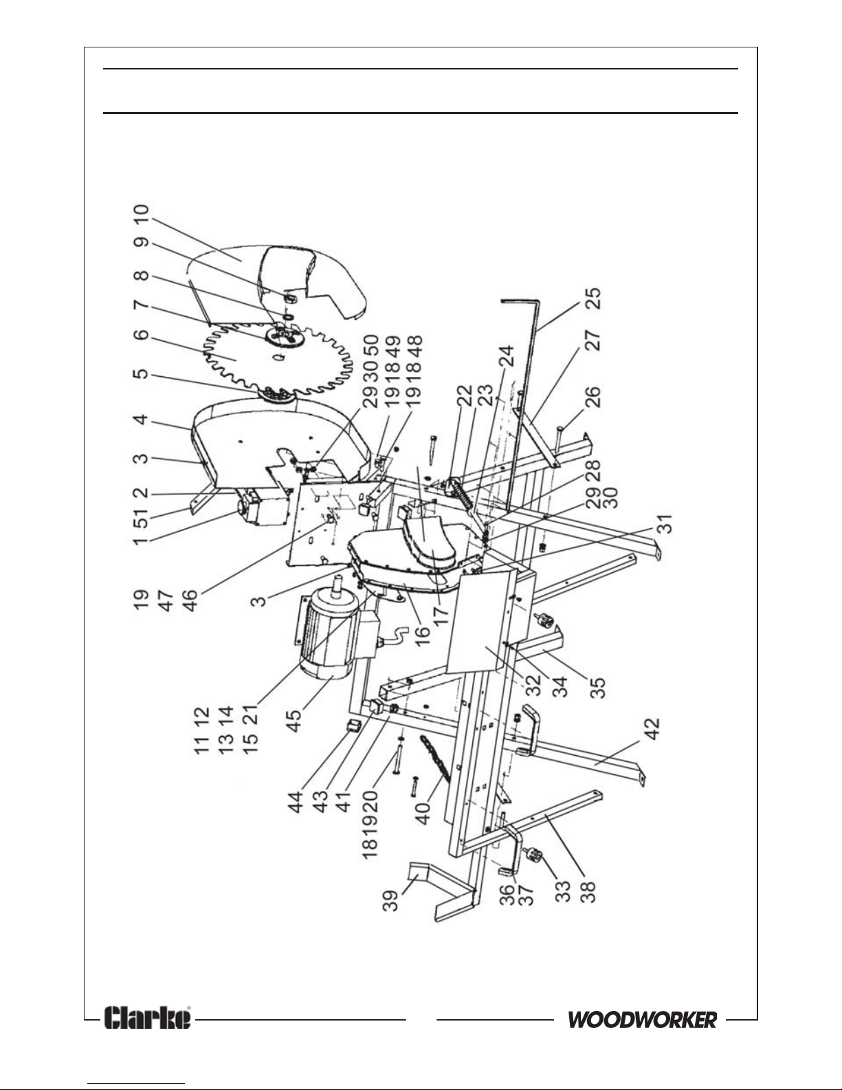
18
Parts & Service: 020 8988 7400/E-mail:[email protected] or [email protected]
COMPONENT PARTS DIAGRAM
Page 19

19
Parts & Service: 020 8988 7400/E-mail:[email protected] or [email protected]
DECLARATION OF CONFORMITY
Page 20

 Loading...