

Page 1
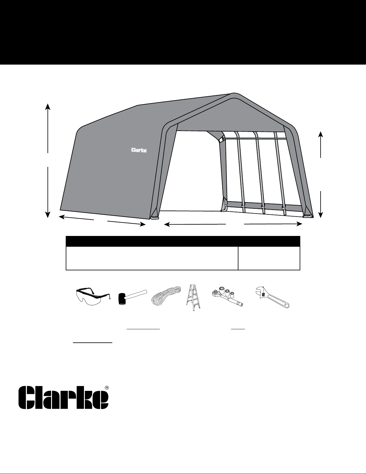
Instant Garage
Assembly Instructions
C
16' x 12' 3" x 8' 6"
Door
Height
1.8M
A
DESCRIPTION MODEL #
A B C
Instant Garage 4.9 x 3.7 x 2.6 M - Grey
16' x 12' 3" x 8' 6"
RECOMMENDED TOOLS
Please read instructions COMPLETELY before assembly. This shelter MUST be securely anchored.
Before you start: 2 or more individuals recommended for assembly, approximate time 2 hours.
B
CIG 1216
3503500
OR
Clarke International
Hemnall Street
Epping
Essex CM16 4LG
ENGLAND
www.clarkeinternational.com
3/30/12
Page 1
PARTS & SERVICE: 0208 988 7400
E-mail: [email protected] or
SALES: UK 01992 565333 or
EXPORT: 00 44 (0)1992 565335
05_62699_0A
Page 2
ATTENTION:
This shelter product is manufactured with quality materials. It is designed to t the garage custom fabric cover included. Please anchor
the shed carefully following the instructions in the manual. Proper anchoring, keeping cover tight and free of snow and debris is the
responsibility of the consumer. Please read and understand the installation detail, warnings and cautions prior to beginning installation.
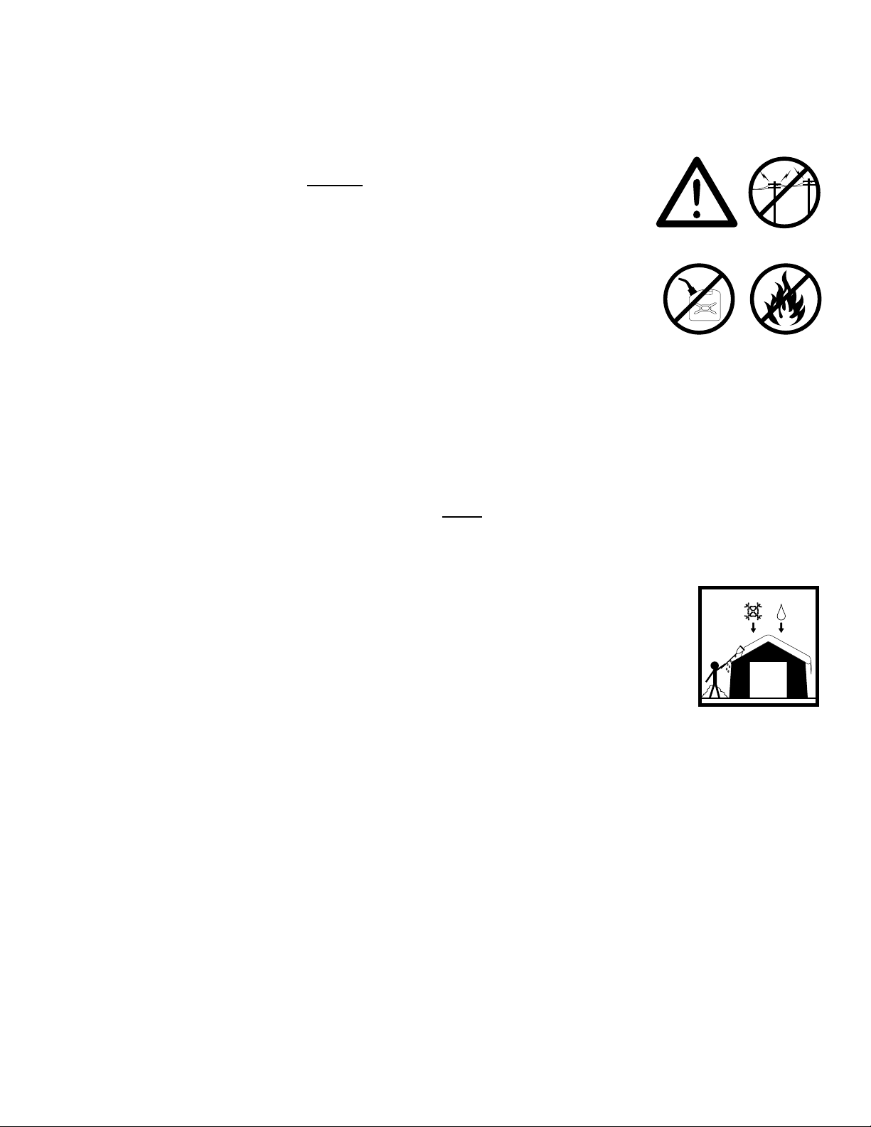
DANGER:
Choose the location of your garage carefully. DANGER: Keep away from electrical wires. Check for
overhead utility lines, tree branches or other structures. Check for underground pipes or wires before
you dig. DO NOT install near roof lines or other structures that could shed snow, ice or excessive run
off onto your shelter. DO NOT hang objects from the roof or support cables.
WARNING:
Risk of re. DO NOT smoke or use open ame devices (including grills, re pits, deep fryers, smokers or
lanterns) in or around the garage. DO NOT store ammable liquids (gasoline, kerosene, propane, etc.) in
or around your shelter. Do not expose top or sides of the shelter to open re or other ame source.
CAUTION:
Use CAUTION when erecting the frame.
PROPER ANCHORING AND INSTALLATION OF FRAME:
PROPER ANCHORING OF THE FRAME IS THE RESPONSIBILITY OF THE CONSUMER.
Clarke® International is not responsible for damage to the unit or the contents from acts of nature. Any garage that is not anchored
securely has the potential to y away causing damage. Periodically check the anchors to ensure stability of the garage. Clarke
International cannot be responsible for any shelter that blows away. NOTE: Your shelter’s cover can be quickly removed and stored
prior to severe weather conditions. If strong winds or severe weather is forecast in your area, we recommend removal of cover.
®
CARE AND CLEANING:
A tight cover ensures longer life and performance. Always maintain a tight cover. Loose fabric can accelerate
deterioration of cover fabric. Immediately remove any accumulated snow or ice from the roof structure with a
broom, mop or other soft-sided instrument. Use extreme caution when removing snow from cover- always
remove from outside the structure. DO NOT use hard-edged tools or instruments like rakes or shovels to
remove snow. This could result in punctures to the cover. DO NOT use bleach or harsh abrasive products to
clean the fabric cover. Cover is easily cleaned with mild soap and water.
Page 2
05_62699_0A
Page 3
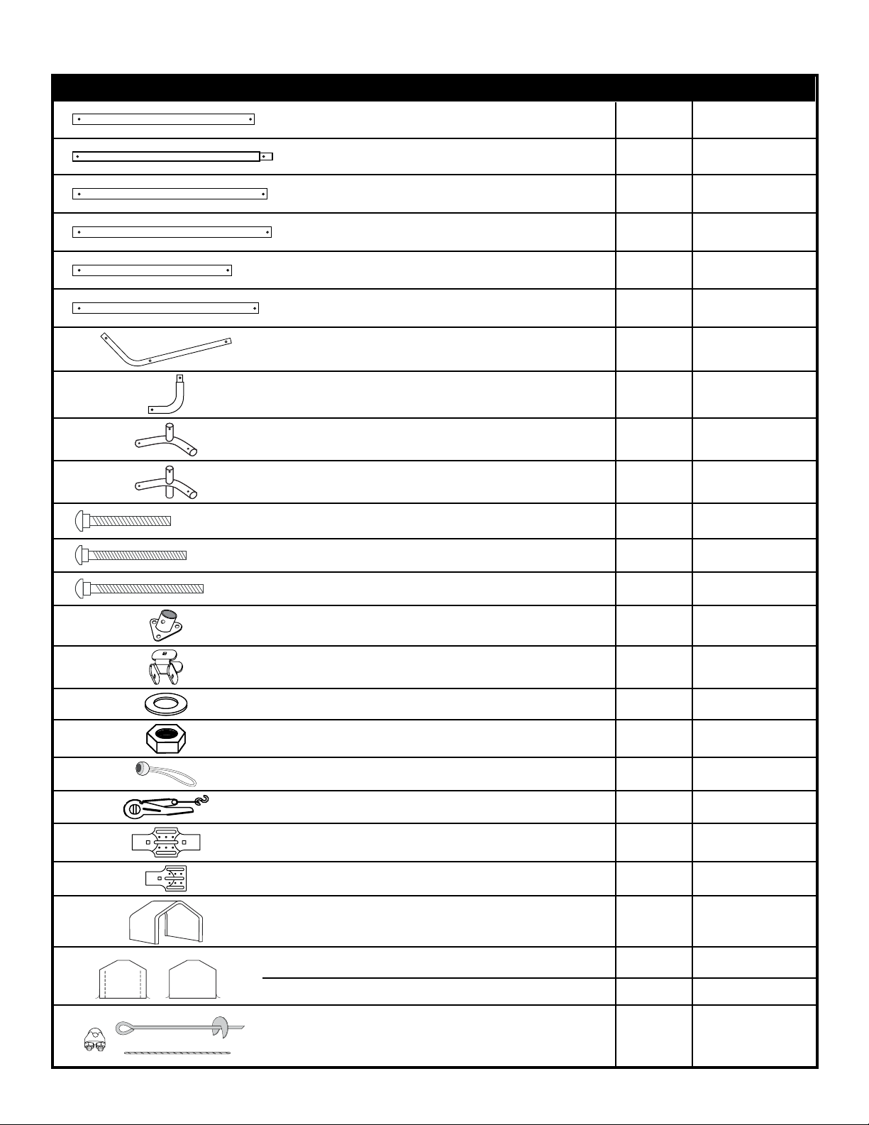
Instant Garage 16' x 12'3" x 8'6" - Parts List - Model # CIG 1216 3503500
Quantity Part #Description of Parts:
Top Cross Rail 45
3
in. / 115,3 cm
/
8
4
801258
Side Cross Rails, Swedge 49
Rafter / Cross Rail 48
Middle Leg Pipe 49
Corner Leg Pipe 39
Cover Rails 46
Side Bends
Corner Leg Bends
3-Way Top Connectors
4-Way Top Connector
1
Bolts
Bolts
5
x 1
/
4
1
/
4
in. / 6,4 x 41,3 mm
/
8
7
x 1
in. / 6,4 x 47,6 mm
/
8
3
in. / 126,4 cm
/
4
1
in. / 123,2 cm
/
2
5
in. / 126,1 cm
/
8
1
in. / 100,3 cm
/
2
1
in. / 117,2 cm
/
8
6
12
6
4
8
10
4
2
3
26
48
802129
802130
802693
802694
802695
801209
802637
801256
801257
10115
03032
Bolts
Steel Foot Plate
Washer
Nut
Ratchet Clamp
Half-Clamps for Middle Legs
Half-Clamps for Corner Legs
Cover
2-Zipper Door Panel
Back Panel
1
x 2 in. / 6,4 x 50,8 mm
/
4
1
in. / 6,4 mm
/
4
1
in. / 6,4 mm
/
4
10
6
10 800938Shelter Stabiliser
16
84
2 10066White Bungee Cords (For holding door open)
8
12
8
1
1
1
10114
12270
01011
01010
10240
13201
13202
803079
803081
803080
15 in. Anchors
Cable - 1 ft. Length
Cable Clamps
NOTE: 15 inch anchors are available from our spare parts
department. Please quote Part No. 10014
Page 3
4
4
4
10014
10015
10016
00847
}
05_62699_0A
Page 4
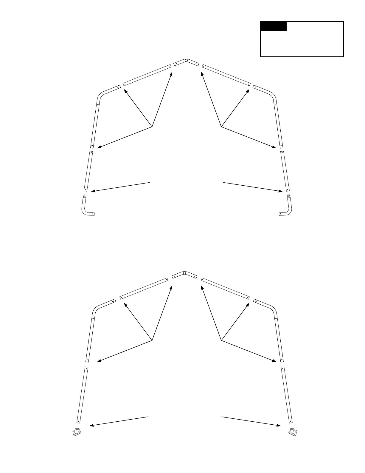
1. ASSEMBLE 2 END RIBS
Secure connections using Bolts as shown with #01010 Nuts.
801256
NOTE:
The bolt heads at
the end ribs must be facing
outward to avoid damaging
your cover.
802130
801209
#03032 Bolts (1
802694
#10115 Bolts (1
7
5
/
8
/
8
802130
801209
")
802694
")
802637 802637
2. ASSEMBLE 3 MIDDLE RIBS
802130
801209 801209
802693 802693
801277
#03032 Bolts (1
#10115 Bolts (1
802130
7
")
/
8
5
")
/
8
12270
Page 4
12270
05_62699_0A
Page 5
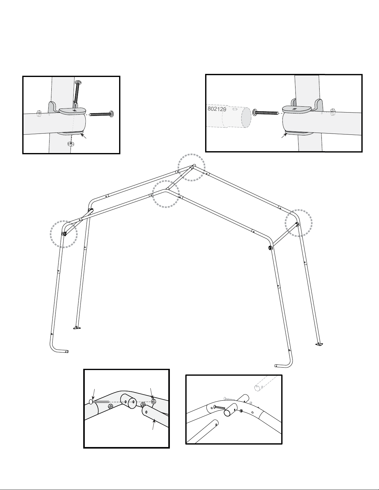
3. CONNECT FRONT END RIB TO A MIDDLE RIB
802129
A. Connect 2 Side Cross Rails (802129) at front end rib with Shelter Stabiliser (800938) as shown.
B. Connect Side Cross Rails at middle rib with Shelter Stabiliser as shown. Leave open for next rib connection.
C. Use Top Cross Rail (801258) to connect ribs at the top.
A
01010
802130
A
801209
03032
01010
802130
800938
10114
801258
C
B
10114
800938
801209
01010
802130
C
B
802130
C
03032
801256
01010
801258
C
Page 5
801258
03032
01010
801257
801258
05_62699_0A
Page 6
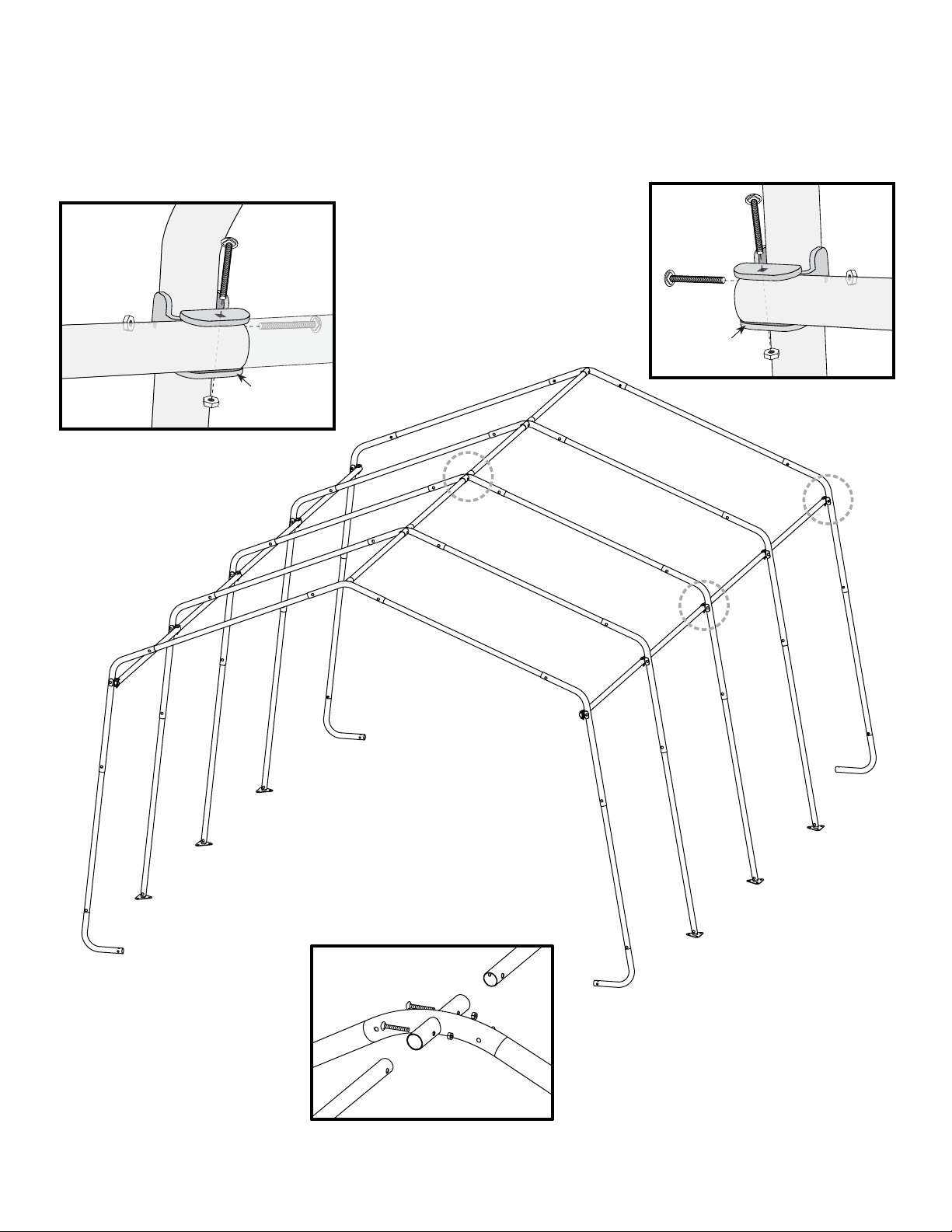
4. CONNECT REMAINING RIBS
A. Use #802130 Side Cross Rails and Shelter Stabiliser (800938) to connect middle ribs as shown.
B. Use #802129 Side Cross Rails and Shelter Stabiliser to connect rear end rib.
C. Use Top Cross Rail (801258) to connect ribs at the top.
A
01010
802129
801209
01010
03032
800938
10114
802129
C
801258
801258
801258
B
A
801209
03032
0101010114
802129
800938
01010
B
802129
802129
802129
C
03032
801258
801258
01010
801257
Page 6
05_62699_0A
Page 7
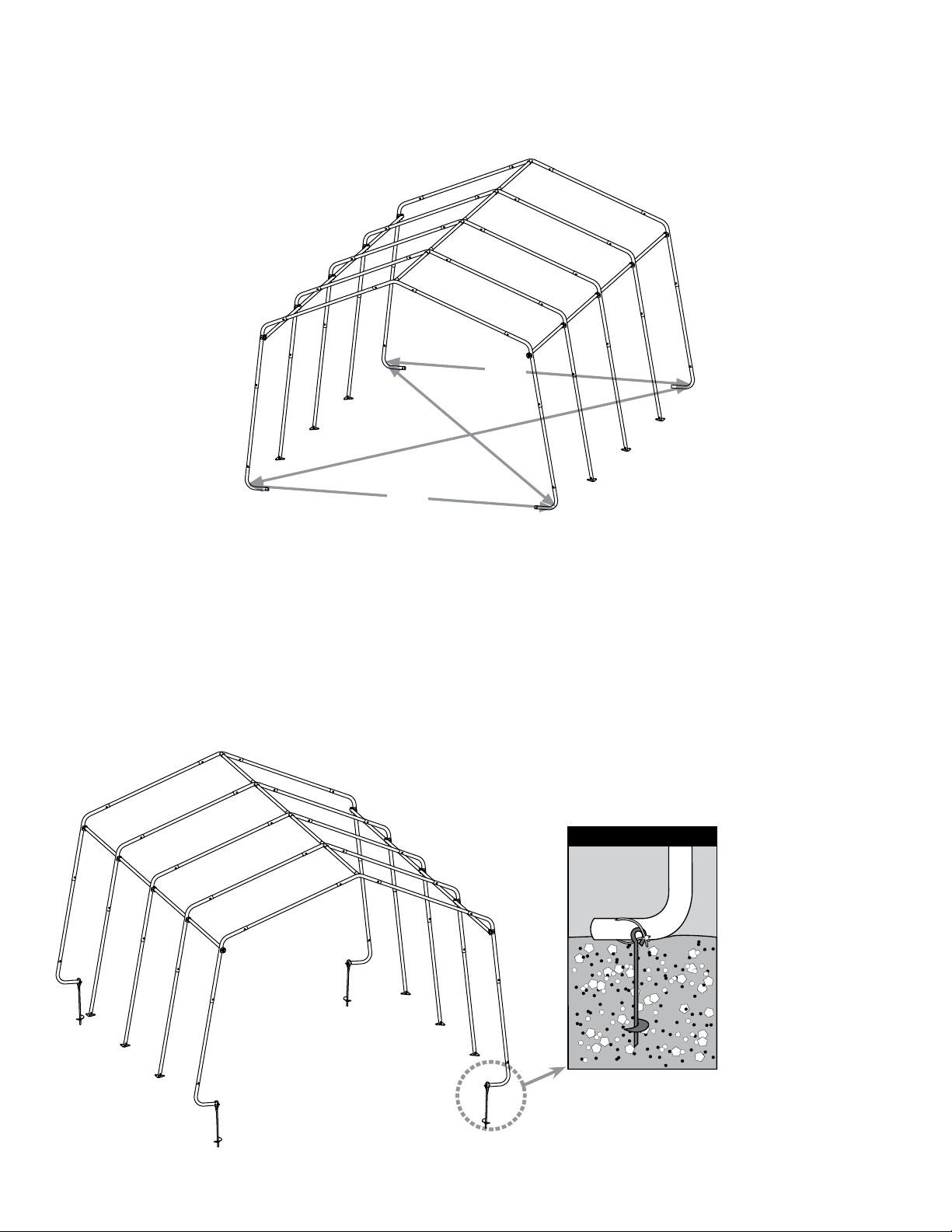
5. SQUARING UP THE FRAME
A. Place frame in its nal location, which needs to be as at and level as possible.
B. Measure across opposite corners. These distances must be equal to within 1 inch.
C. Check that the front and rear of the frame measures 12 feet in width
12 ft.
12 ft.
6. PROPERLY ANCHOR THE FRAME
A. Anchors must be placed inside shelter at the corners of the shelter.
B. Insert a ¾ inch pipe or steel rod, through the eyelet of the auger and screw the anchor into the ground until
the eyelet is sticking out of the ground by 1 to 2 inches so it can be anchored to the legs.
C. Wrap cable provided through the eyelet of the anchor and around the frame as shown below. Secure
the cable with the clamps provided.
If ground is too hard, dig a hole with a shovel or post hole tool. Optional: Fill with cement.
End Rib Anchors
WARNING:
Serious injury to persons
or property could result
if cover is installed and
shelter is not anchored
and is left unattended.
Shelter must be securely
anchored before use.
Page 7
05_62699_0A
Page 8
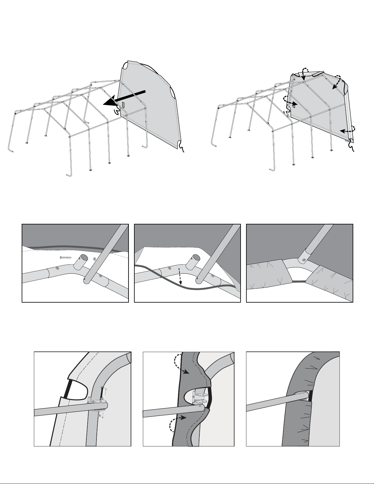
7. DOOR PANEL AND BACK PANEL INSTALLATION
A. (1) Hold end panel at the top center with white inner surface facing inside of the shelter. (2) Wrap the edges
of the fabric panel around the end rib and line up the cross rails with the pre made slits in the fabric.
A1 A2
B. (1) Disconnect top cross rail (the horizontal pipe that runs from front to back along the top) from the end rib.
(2) Pull the end panel over the end rib and bring the end of the cross rail through the cut slit in the panel.
(3) Reattach the top cross rail to the end rib.
B1 B2 B3
C. (1) Disconnect side cross rail from the end rib. Leave the Shelter Stabiliser attached to the rib with the bolt.
(2) Pull the end panel over the end rib and bring the end of the cross rail through the cut slit in the panel.
(3) Reattach the side cross rail to the end rib.
C1 C2 C3
Page 8
05_62699_0A
Page 9
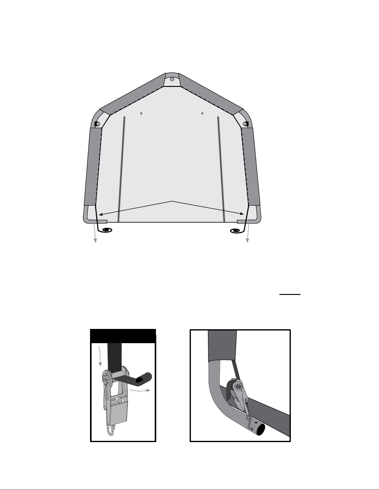
7. END PANEL INSTALLATION - continued
D. At the bottom, where the webbing exits the pocket on each side of end panel, pull webbing as you would a
drawstring to remove the slack. Be careful not to pull the webbing strap out of the webbing pocket.
D
END PANEL VIEW
FROM INSIDE
GARAGE
WEBBING
STRAP
PULLPULL
E. Insert the “S”- Hook on ratchet into hole on the leg bend. Insert the webbing into the spindle of the ratchet
and pull tight. Wind the ratchet so that the webbing overlaps itself. Position the end panel so that it is
centered on the building before fully tightening the end panel.
F. Tighten ratchets, alternating from one side to the other, until the end panel is tight. NOTE: Keep zips
fastened when tightening door panel.
E F
Insert Webbing into
Ratchet
Page 9
05_62699_0A
Page 10
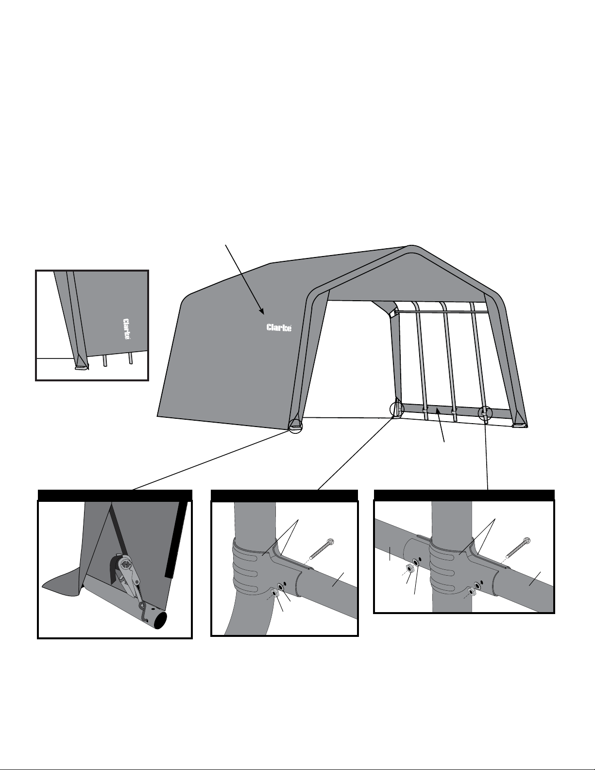
8. INSTALLING COVER AND COVER RAILS
A. Lay the cover on the ground next to the frame with inside of the cover (the side with the pipe pockets) facing
down and the webbing on the front and rear of the corner of the building.
B. Pull cover over the frame, making sure to center cover on frame. There should be an equal amount of over-
hang at all four corners.
C. Insert the “S”- Hook on ratchet into hole on the leg bend. Insert the webbing into the spindle of the ratchet
and pull tight. Wind the ratchet so that the webbing overlaps itself.
D. Disassemble cover rails and slide through fabric pockets at each leg and reattach with clamps to each leg.
Repeat this on other side. Push down on cover rails to tighten cover, before tightening bolts completely.
E. Check and tighten Ratchets and Cover Rails monthly to ensure the cover is tight.
NOTE: The Clarke® logo should
be oriented as shown below.
CORRECT
INCORRECT
REAR
Webbing and Ratchets Securing Cover
End Rib Cover Rail Clamps
Corner
Leg
13202
10115
01011
01010
802695
802695
01010
802695
COVER RAILS
Middle Rib Cover Rail Clamps
01011
Middle
Leg
13201
FRONT
10115
802695
Page 10
05_62699_0A
 Loading...