

Page 1
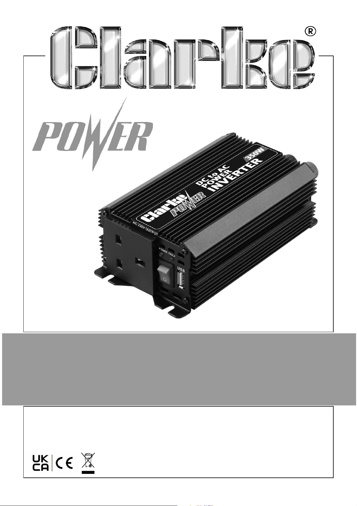
350W POWER INVERTER
MODEL NO: CI350
PART NO: 6013031
USER INSTRUCTIONS
ORIGINAL INSTRUCTIONS DL06/23
Page 2
INTRODUCTION
Thank you for purchasing this CLARKE product. Before attempting to use this
product it is essential that you read this manual thoroughly and carefully follow
all instructions given. In doing so you will ensure the safety of yourself and that
of others around you and you can also look forward to the inverter giving you
long and satisfactory service. When unpacking, any damage or deficiency
should be reported to your CLARKE dealer immediately.
PRINCIPLES OF THE INVERTER
The inverter is a power conversion device which converts the DC power of the
battery into AC power and supplies power to small electrical appliances and
digital products. It gives a continuous 230V, 50Hz power supply via a standard
3-pin socket.
Household appliances include TVs, camcorders, laptops, lamps and power
tool chargers etc, depending upon the rating of the inverter.
It is designed with five protection functions for Input low voltage, Input over
voltage, Overload, Over temperature and Output short circuit. These five
functions can protect the electrical equipment and the circuit of the vehicle.
This CLARKE product has been designed to give long and trouble free service.
If, however, having followed the instructions in this booklet carefully, you
encounter problems, take the unit to your local CLARKE dealer.
SAFETY SYMBOLS
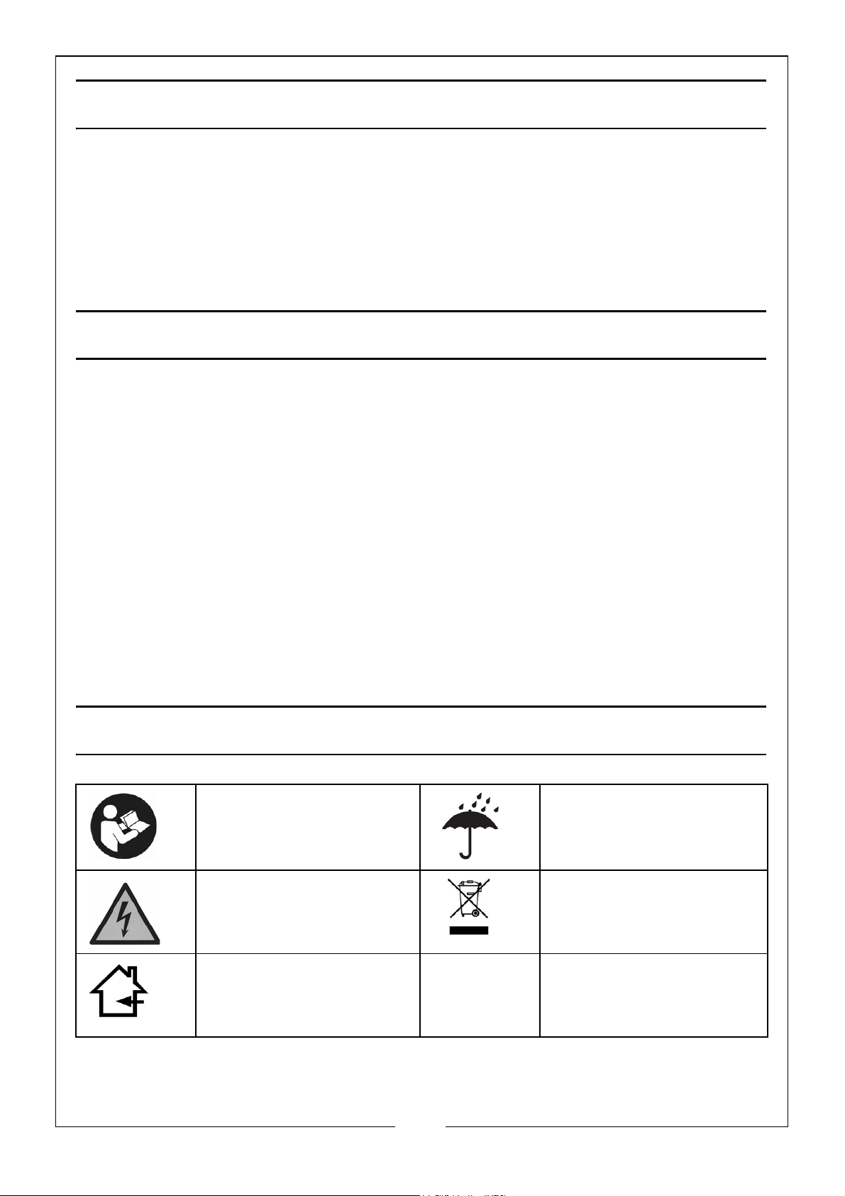
Read this instruction
booklet carefully
before use.
Risk of Electrical Shock Recycle unwanted
Do not expose to rain.
materials under WEEE
Directive
Use Indoors Only
2
Parts & Service: 020 8988 7400 / E-mail: [email protected] or [email protected]
Page 3

GENERAL SAFETY PRECAUTIONS
1. ALWAYS stay alert, watch what you are doing and use common sense
when using this product. DO NOT use the product when you are tired or
under the influence of medication, drugs or alcohol. A moment of
inattention can result in personal injury.
2. ALWAYS thoroughly familiarise yourself with this product & its operation, and
always read and understand the instructions and warnings in this manual
before using the equipment.
3. NEVER dismantle the unit. ALWAYS return this product to the dealer if any
problem is found.
4. Keep out of the reach of children.
5. ALWAYS have the unit repaired by your local CLARKE dealer, using only
identical replacement parts. This will ensure the safety of the unit is
maintained. The use of non standard parts could be hazardous.
6. DO NOT use with positive earth systems (most modern vehicles, lorries,
boats etc, are negative earth). Reverse polarity connection will result in a
blown fuse and may cause permanent damage to the inverter.
7. DO NOT use in a wet environment or with wet hands.
8. DO NOT install inside an engine compartment - the inverter must always be
installed in a well ventilated area.
9. DO NOT use in potentially explosive atmospheres such as garage
forecourts etc.
10. NEVER connect to an AC supply.
11. ALWAYS disconnect the appliance from the inverter before making
adjustments to the appliance being run.
12. The outer shell may be hot after long periods of use so take care when
handling.
13. This inverter is NOT tested for use with medical devices.
14. ONLY use for class II appliances. as the unit has no earth connection.
3
Parts & Service: 020 8988 7400 / E-mail: [email protected] or [email protected]
Page 4
PRODUCT SPECIFICATIONS
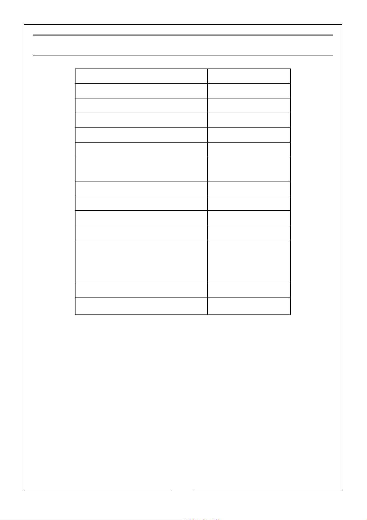
Model CI350
Unpacked Weight 775g
Dimensions (L x W x H) (mm) 180 x 102 x 66
Nominal DC Input 13V (+/- 0.2)
Input working DC voltage 11-15V
Input full load current 36A
Output voltage AC 230V+/-10%,
Output Power 350W
Peak output power (0.1 sec) 700W
Output wave Modified sine wave
5V DC (USB)
Max efficiency 85%
Protection devices Thermal overload,
Low voltage,
Over voltage &
short circuit
Fuse (blade type) 40A
Operating temperature
NOTE: The details and specifications contained herein, are correct at the
time of going to print. However, CLARKE International reserve the
right to change specifications at any time without prior notice.
5-35
o
C
4
Parts & Service: 020 8988 7400 / E-mail: [email protected] or [email protected]
Page 5
PRODUCT FEATURES
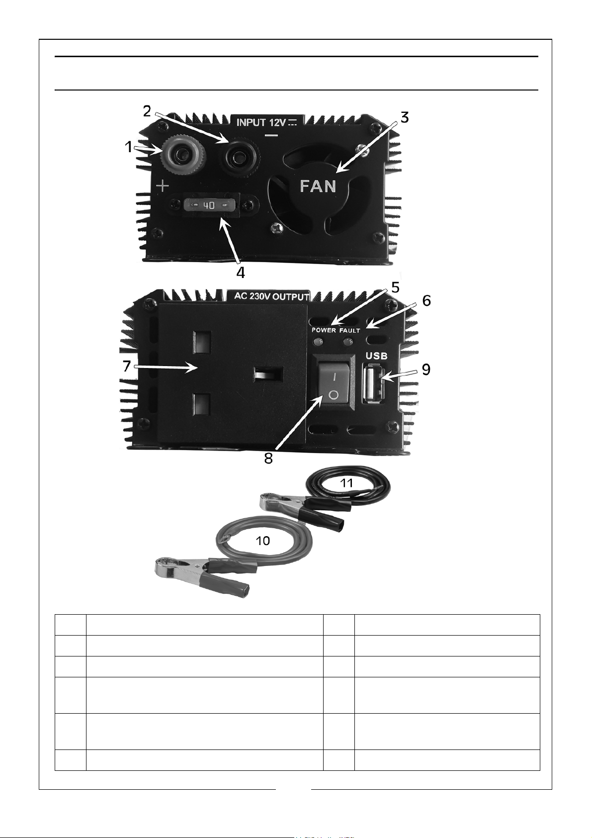
1 DC Input Positive + Terminal (Red) 7 AC 230V Output Socket
2 DC Input Negative - Terminal (Black) 8 On/Off Switch
3 Cooling Fan (Thermally Controlled) 9 USB Port
4 40A External Fuse 10 Positive + (Red) Connection
Cable
5 Power LED Light (Green) 11 Negative - (Black)
Connection Cable
6 Fault LED Light (Red)
5
Parts & Service: 020 8988 7400 / E-mail: [email protected] or [email protected]
Page 6

GENERAL OPERATION
CONTROLS, INDICATORS AND CONNECTORS
An ON/OFF switch turns the inverter on and off and will reset the inverter
internal circuits.
One end panel provides DC connections for battery clamps and a 40A fuse. A
230V AC 3 pin plug socket and a USB connector is provided on the other end
together with two LEDs (green and red) and the On/Off switch.
• The GREEN LED illuminates when the inverter is connected, switched ON,
and working correctly.
• The RED LED, when illuminated, indicates that the inverter is in a fault
condition and has shutdown from overload, excess voltage or
overheating, see page 12 for more details.
SUITABLE POWER SOURCES
In order to operate the inverter and supply power to an appliance, a suitable
DC power supply is required. This can be a vehicle or caravan battery,
portable power pack, or an independent 12 Volt battery. For most
applications, a ‘deep cycle’ battery is recommended for best performance.
The size of the battery used will determine how long the inverter will supply
power to an appliance and how well the inverter will perform. Most batteries
are marked with their size in Amp Hours (A/h).
Because 12 Volt inverters are capable of drawing high currents the inverter
should only be connected to a suitable size battery. Connection to an
undersized battery could damage the battery and will result in the inverter
shutting down within a short period due to low battery voltage. The amount of
power drawn from the battery is proportional to the inverter load.
To avoid excessively discharging the vehicle battery, it is advisable to let your
engine run for a while after a period of using the inverter. This allows the
vehicle battery to recharge.
ALWAYS remember to disconnect the AC inverter before using a battery
charger to recharge your battery. Failure to disconnect the inverter prior to
connecting a charger may result in an input spike which will damage the
inverter. CONNECTING THE INVERTERS INPUT TO A BATTERY CHARGER WILL VOID
THE WARRANTY.
6
Parts & Service: 020 8988 7400 / E-mail: [email protected] or [email protected]
Page 7

CONNECTION AND POSITIONING
Connecting the inverter in the wrong way may damage the inverter as well as
the electrical equipment. Please follow the steps below to avoid connection
errors.
CONNECTING TO A BATTERY
1. Insert the ring terminal end of the Positive (Red, +) connection cable into
the DC input Positive (Red, +) terminal on the inverter and tighten the
holding screw.
2. Insert the ring terminal end of the Negative (Black, -) connection cable into
the DC input Negative (Black, -) terminal on the inverter and tighten the
holding screw.
3. Before connecting the cables to the battery, make sure the inverter On/Off
switch is in the Off position.
4. Connect the crocodile clip ends of the Positive (Red, +) connection cable
to the Positive (Red, +) terminal of the battery.
5. Connect the crocodile clip ends of the Negative (Black, -) connection
cable to the Negative (Black, -) terminal of the battery.
NOTE: DO NOT reverse these connections as this may damage the
inverter.
6. Turn on the inverter using the On/Off switch, this will illuminate the green
LED light.
7. Insert the plug of the electric equipment into the AC socket of the inverter
and switch on the equipment.
POSITIONING OF THE INVERTER
The inverter should always be placed on a flat, level surface and should only
be used in locations that meet the following criteria:
DRY - DO NOT allow water/other liquids to come into contact with the inverter.
COOL - DO NOT place the inverter on or near a heating vent or any piece of
equipment which is generating heat. Keep the inverter away from direct
sunlight.
VENTILATED - Keep the area surrounding the inverter clear to ensure free air
circulation around the unit. DO NOT block the cooling fans. DO NOT place
items on or over the inverter during operation. The unit will shut down if the
internal temperature exceeds 60
SAFE - DO NOT use the inverter near flammable materials or in locations that
may accumulate flammable vapours.
Parts & Service: 020 8988 7400 / E-mail: [email protected] or [email protected]
o
C. The unit will restart after it cools down.
7
Page 8

CAUTION: THE INVERTER MUST BE CONNECTED ONLY TO BATTERIES WITH A
NOMINAL OUTPUT VOLTAGE OF 12-VOLTS. THE UNIT WILL NOT OPERATE FROM A
6-VOLT BATTERY AND WILL SUSTAIN DAMAGE IF CONNECTED TO A 15-VOLT
BATTERY OR HIGHER. MAKE SURE THAT THE BATTERY’S VOLTAGE NEVER EXCEEDS
15-VOLTS, AS THIS WILL INVALIDATE THE WARRANTY.
CAUTION: DO NOT USE WITH POSITIVE EARTH ELECTRICAL SYSTEMS (MODERN
VEHICLES AND LORRIES ARE NORMALLY NEGATIVE EARTH).
EXTENSION CABLES
AV OI D using an extension cable between the DC power source (battery) and
the inverter DC input. Using an extension this way would create a voltage drop
causing reduced efficiency and output. Any extension cable can be used
between the inverter AC output and the AC appliance but greater lengths will
result in a noticeable drop in power.
Any cable used between the appliance and the inverter must be of suitable
diameter and length, otherwise power loss or reduced operating time may
occur.
Marine installations are also subjected to vibration and stresses that exceed
those of other mobile installations. Therefore ensure all connections are tight,
water resistant and have suitable strain relief for DC cables etc. Cable
installation must be the correct type for the environment.
Position the inverter as far away as possible from any television, the antenna
and the antenna cable.
RECHARGABLE DEVICES
Most of these devices use a separate charger or transformer that is plugged
into an AC socket. The inverter is capable of running most chargers and
transformers.
USING THE USB PORT
The USB port is only for charging and does not have any data exchange
function.
Before charging, check carefully that the charging current of the appliance is
lower than the USB current. If it is higher than the USB current, DO NOT use it as
it may damage the USB port.
If the inverter makes a beeping sound, switch off the appliance, unplug the
inverter and restart the vehicle engine. The beeping sound is simply the low
battery warning which indicates that the voltage of your vehicle battery is
getting low. The inverter will shut down automatically if you do not restart the
engine and continue the use of the inverter. This will leave the vehicle battery
at about 10.5 VDC, enabling you to start your engine and resume operation of
the inverter.
8
Parts & Service: 020 8988 7400 / E-mail: [email protected] or [email protected]
Page 9

To avoid excessively discharging the vehicle battery, it is advisable to let your
engine run for a while after a period of using the inverter. This allows the
vehicle battery to recharge.
Always remember to disconnect the AC inverter before using a battery
charger to recharge your battery. Failure to disconnect the inverter prior to
connecting a charger may result in an input spike which will damage the
inverter. CONNECTING THE INVERTERS INPUT TO A BATTERY CHARGER WILL VOID
THE WARRANTY.
SCOPE OF THE INVERTER
1. Only use the inverter for class II appliances.
2. DO NOT use with appliances that exceed the rated power of the inverter.
3. DO NOT use with capacitive or perceptual load appliances such as air
condition, high power electric drill, fridge, microwave oven, blender.
4. It is NOT RECOMMENDED using the inverter with appliances which have
strict requirements on power supply, such as precise measuring equipment,
as it may effect the measuring data.
5. Some appliances must charge with their original charger. If this is the case,
DO NOT use the USB port and charge the appliance via the 230V AC
outlet.
9
Parts & Service: 020 8988 7400 / E-mail: [email protected] or [email protected]
Page 10

SYSTEM PROTECTION
The inverter has;
• input low voltage protection,
• input over voltage protection
• over load protection,
• over temperature protection and
• short circuit protection.
If these are activated the inverter will shut down.
After troubleshooting, the inverter will work normally again.
The inverter will switch off automatically if the total wattage of the connected
appliance(s) exceeds the inverter output capacity. This will also happen if the
temperature of the inverter housing reaches proximatly 60
prolonged use.
The protection circuit will also switch off the output in the case of short-circuit
or overload. If this should happen:
o
C due to
1. Switch off the inverter.
2. Disconnect any appliances.
3. Check all connections.
The inverter can be used again when any faults have been rectified.
When the unit is in continuous operation, the AC output may suddenly stop
although there remains a good supply from the battery. This may be caused
by overheating and the inverter should be switched off until it cools down.
MEASURING AC VOLTAGE
The output wave of the AC inverter is a modified sine-wave. If you choose to
measure the AC output voltage, you must use an authentic RMS volt meter.
Using any other type of voltage measuring device will result in an AC voltage
reading that is up to 20 to 30 volts lower than the rated value. The reading will
only be accurate when using an authentic RMS voltmeter.
TYPICAL PROBLEMS DURING OPERATION
EXCESSIVE START-UP LOAD
An appliance can be trying to draw too much power as displayed when a
motorised power tool does not operate at correct speed.
10
Parts & Service: 020 8988 7400 / E-mail: [email protected] or [email protected]
Page 11

PURELY INDUCTIVE LOAD
Make the load not purely inductive. Use an adaptor to operate a lamp at the
same time as the motorised appliance, ensuring the combined load does not
exceed that of the inverter.
SNOW IN TV PICTURE, BUZZ IN SPEAKER
This can be caused by RF interference. Keep the inverter and any antenna
well away from each other. Use a shielded antenna cable.
FUSE REPLACEMENT
If the external fuse on the rear of the unit blows, there is most likely a short
circuit or overload in the DC wiring or the polarity has been reversed. Find and
correct the problem before replacing the fuse.
After fuse replacement, reconnect the inverter and if a fuse continues to blow,
contact your CLARKE dealer or telephone CLARKE International on 020 8998
7400. DO NOT open the unit as there are no user serviceable parts inside.
11
Parts & Service: 020 8988 7400 / E-mail: [email protected] or [email protected]
Page 12

TROUBLESHOOTING
Protection Condition Re-start method
LED light Alarm AC
output
Input low voltage
alarm
Input Low-Voltage
shut down
Input over voltage
shut down
Overload
protection
Green
on/red off
Green on
Red on
Green on
Red on
Green on
Red on
Alarm Yes When the battery voltage
returns to the related voltage, alarm stops automatically.
Alarm No When the battery voltage
returns to the related voltage the inverter will work
normally again (Green
LED on Red off)
No Alarm No When the battery voltage
returns to the related voltage the inverter will work
normally again (Green
LED on Red off)
No Alarm No Reduce the load in the
related range. The
inverter will work normally
again (Green LED on Red
off)
Over-temperature
shutdown
Output short-
circuit
Green on
Red on
Green on
Red on
Alarm No Check fan for any
obstructions. When the
inside temperature
returns to the related
range, the inverter will
work normally again
(Green LED on Red off)
No Alarm No When the short-circuit is
removed the inverter will
restart and work normally.
12
Parts & Service: 020 8988 7400 / E-mail: [email protected] or [email protected]
Page 13
CARE AND MAINTENANCE
No routine maintenance is required but you can clean the exterior of the unit
periodically with a damp cloth to prevent accumulation of dust and dirt. At
the same time check that the screws on the DC terminals are tight.
Never attempt to dismantle the unit due to hazardous voltages. Please return
to the dealer if any problem is found with this unit.
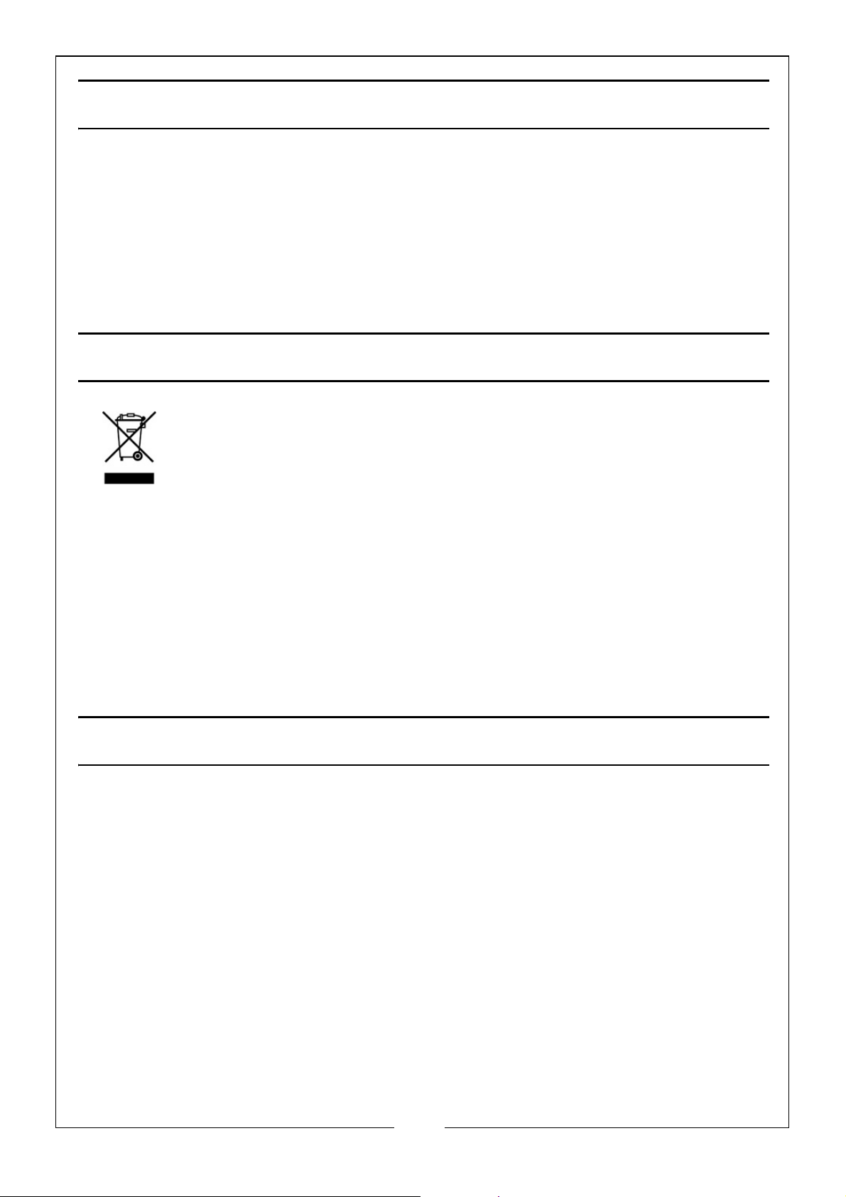
ENVIRONMENTAL RECYCLING POLICY
Through purchase of this product, the customer is taking on the
obligation to deal with the WEEE in accordance with the WEEE
regulations in relation to the treatment, recycling & recovery and
environmentally sound disposal of the WEEE.
In effect, this means that this product must not be disposed of with general
household waste. It must be disposed of according to the laws governing
Waste Electrical and Electronic Equipment (WEEE) at a recognised disposal
facility.
If disposing of this product or any damaged components, do not dispose of
with general waste. This product contains valuable raw materials. Metal
products should be taken to your local civic amenity site for recycling of metal
products.
GUARANTEE
This CLARKE product is guaranteed against faulty manufacture for a period of
12 months from the date of purchase. Please keep your receipt as proof of
purchase.
This guarantee is invalid if the product is found to have been abused or
tampered with in any way, or not used for the purpose for which it was
intended.
Faulty goods should be returned to their place of purchase, no product can
be returned to us without prior permission. This guarantee does not effect your
statutory rights.
13
Parts & Service: 020 8988 7400 / E-mail: [email protected] or [email protected]
Page 14
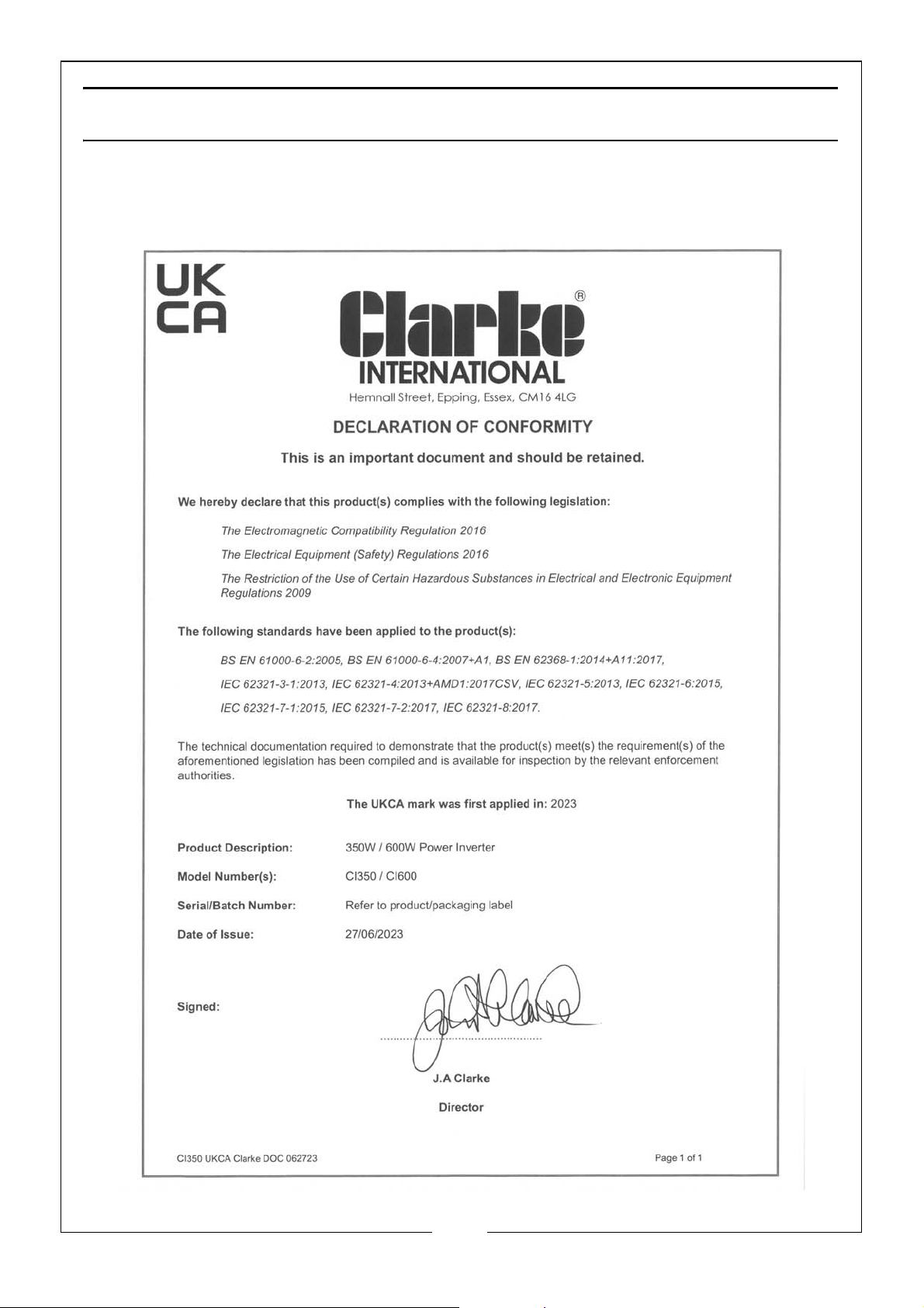
DECLARATION OF CONFORMITY -UK
14
Parts & Service: 020 8988 7400 / E-mail: [email protected] or [email protected]
Page 15
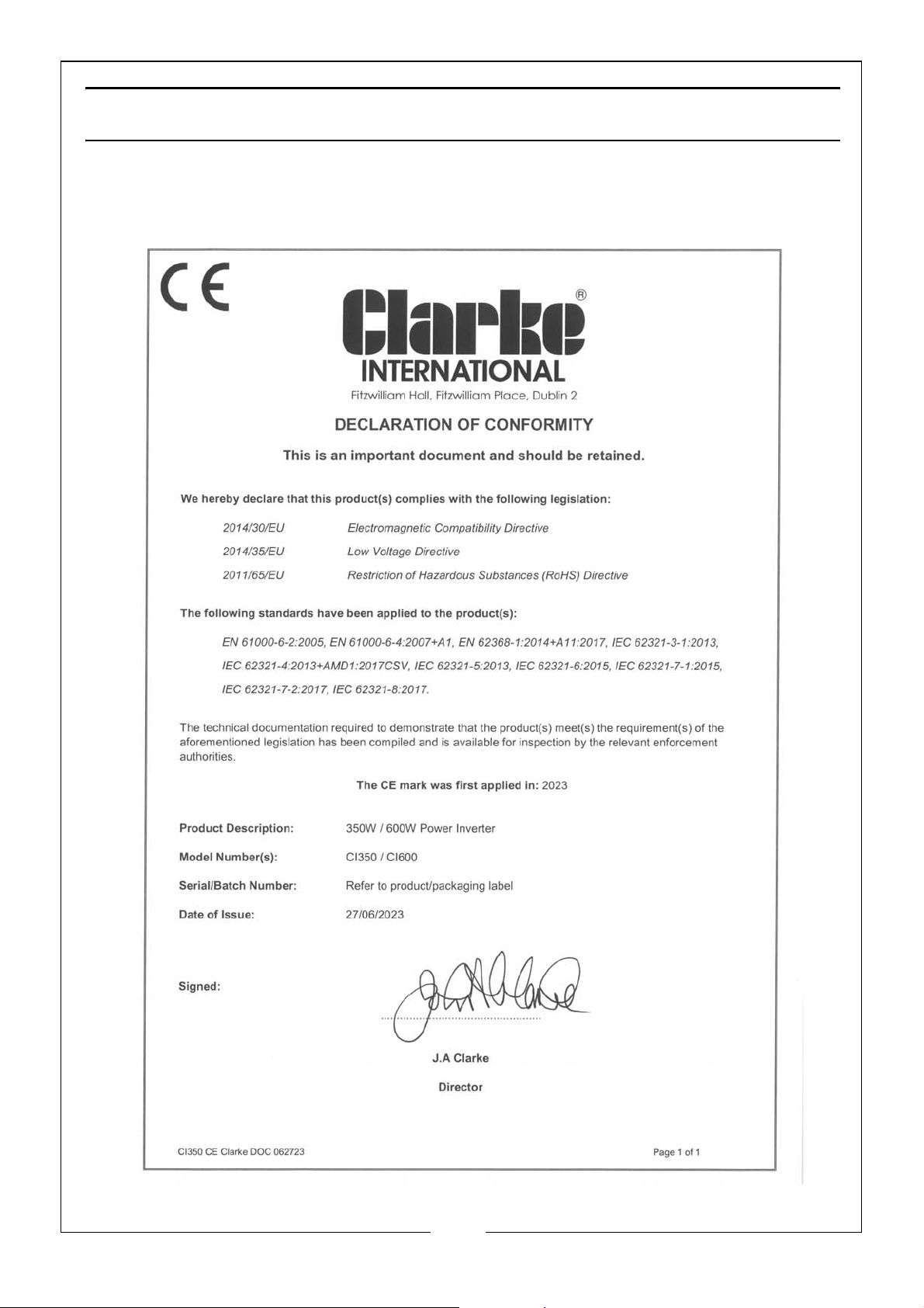
DECLARATION OF CONFORMITY - CE
15
Parts & Service: 020 8988 7400 / E-mail: [email protected] or [email protected]
Page 16

 Loading...