

Page 1
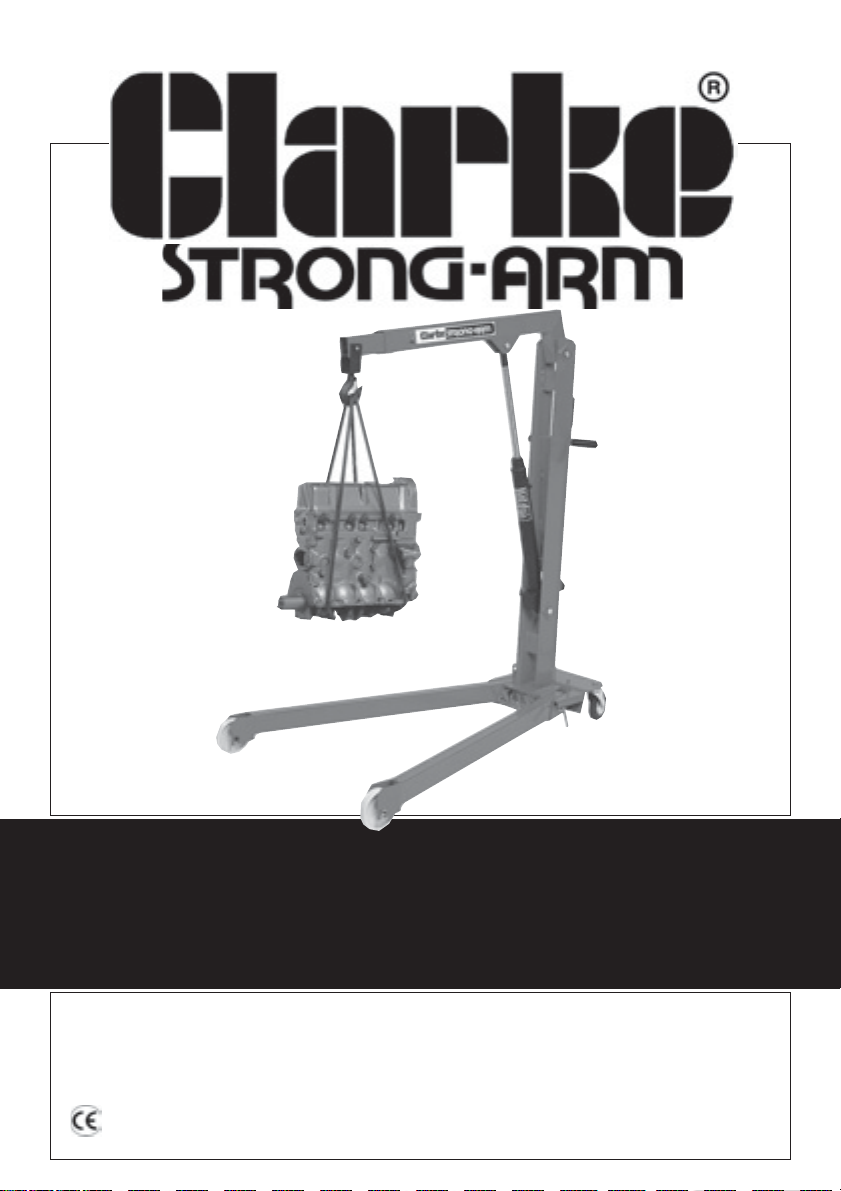
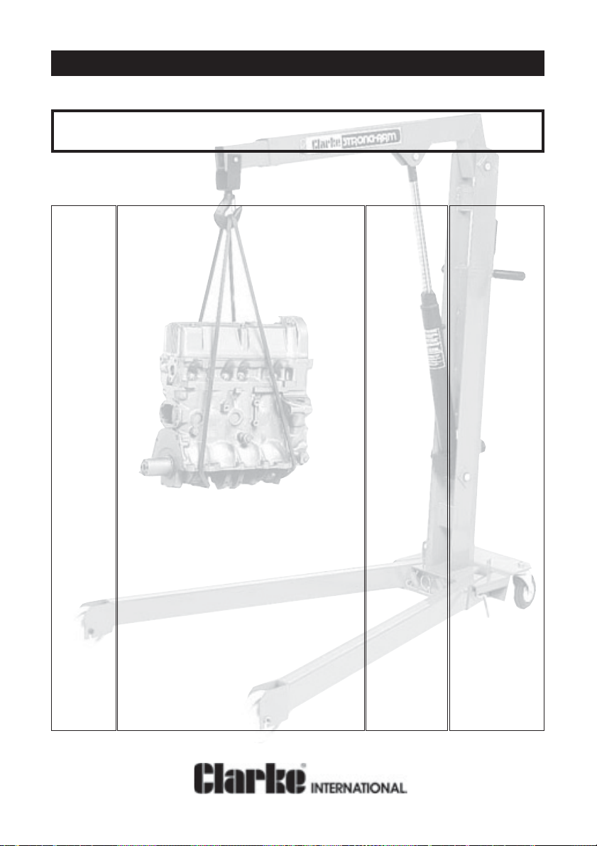
½ TONNE & 1 TONNE FOLDING CRANE
½ TONNE & 1 TONNE FOLDING CRANE
MODELS CHC500DF & CHC1000DF
PART No. 7610500 AND 7611002
OPERATION &MAINTENANCE
INSTRUCTIONS
0502
Page 2

Please read these instructions carefully before operating the truck
Thank you for purchasing this CLARKE Strong-Arm Hydraulic Crane.
Before using the device, please read this manual thoroughly and carefully follow all
instructions given. This is for your own safety and that of others around you, and is also to
help you achieve a long and trouble free service from your new truck.
CLARKE GUARANTEE
This CLARKE product is guaranteed against faulty manufacture for a period
of 12 months from the date of purchase. Please keep your receipt as proof
of purchase.
This guarantee is invalid if the product is found to have been abused or
tampered with in any way, or not used for the purpose for which it was
intended.
Faulty goods should be returned to their place of purchase, no product can
be returned to us without prior permission.
This guarantee does not affect your statutory rights.
PARTS & SERVICE TEL: 020 8988 7400
or e-mail as follows:
PARTS: [email protected]
SERVICE: [email protected]
Page 3
Safety Precautions
WARNING
Failure to comply with these rules and precautions, may result in loss of
load, damage to, or failure of the equipment, or even personal injury .
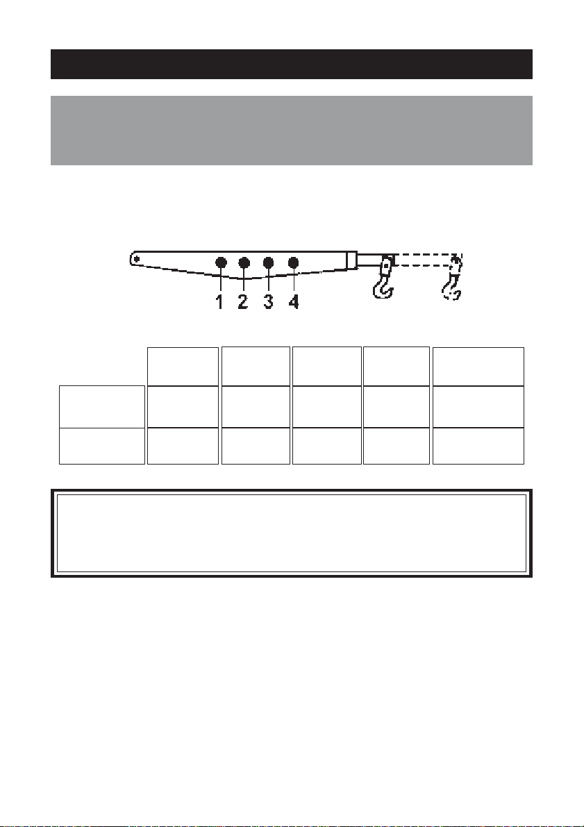
1. DO NOT exceed the load capacity for each jib position (as marked on the
jib). The capacities for each model are shown in tables on the inside front
cover.
1 2 3 4 Max Lift Ht
CHC500DF 500 400 350 250 2000mm
CHC1000DF 1000 800 650 450 2450mm
IMPORT ANT :
If the load capacity decal becomes worn or illegible, contact Clarke
International Spares Division, on 020 8558 6696 for replacement.
2. Ensure that the equipment is correctly assembled, and that all the bolts and
pins are in place and secure.
3. Only use chains, slings, hooks etc. with a rated capacity equal to, or greater
than that of the load. Check that they are secure and will not slip under load.
4. Only use the crane on a solid, flat, level surface which is capable of taking
the load. Avoid moving the crane over rough surfaces.
5. Lower the load as much as possible before moving the crane. Do not use the
crane to transport loads.
6. Do not stand under the load, or above the jib. Be aware that if the load slips
or falls, the jib may rise suddenly.
Page 4

7. Use appropriate safety equipment, such as protective footwear, when using
this crane.
8. Ensure the crane operator is skilled and trained in both operation and safety
aspects.
9. Always inspect the crane before use to ensure it is in good condition, and
replace any damaged or worn parts.
10. When replacing parts, use only those supplied by Clarke International. Refer
to Parts List.
11. Ensure that the crane is properly maintained, and lubricated at all times, and
that no rust or other forms of corrosion is allowed to weaken any part of the
crane.
12. If the crane has been subjected to an abnormal load or shock, it should be
removed from service immediately and fully inspected by qualified personnel.
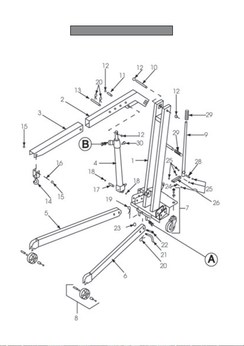
Preparation For Use. Figures in brackets refer to parts list on page 7.
The crane is packed, fully assembled, in the fully folded position. On unpacking
check to ensure that no damage occurred during transit, and that all parts are
present according to the packing list.
1. Withdraw the locking pins (Item 21), lower the legs, and lock in position with
the same pin, securing with the ‘R’ clip (Item 20).
2. Release the stabilising foot (Item A), by removing the ‘R’ clip (Item 19), and
rotating the foot so that it faces upwards. Secure in position with ‘R’ clip.
3. Before operating the crane, remove the transit plug from the back of the
hydraulic ram unit , and replace with the vent plug supplied. retain the transit
plug which should be re-fitted if the crane is stored or transported horizontally.
3. Test the operation of the crane without a load (refer to ‘Operation’ for raising
and lowering the jib). If the ram operation appears ‘spongy’, it is possible that
air may have entered the system. Raising the lowering the jib a few times will
dispel any air and normalise the ram operation.
If the jib does not reach its full height, the rams hydraulic oil may need topping
up, (ref ‘Maintenance’).
Page 5

Operation
IMPORTANT: Before attempting to lift, ensure the hook is directly above the point
of lift, and the point of lift is directly above the centre of gravity on the load.
Select the required jib arm length according to the load to be lifted and access
available. Always use the shortest jib length possible to give the greatest safety
margin and stability. Lock the jib extension into position with the link pin ( Item 13),
and ‘R’ clip (Item 20).
To raise the jib arm, screw the large valve knob (Item B), on the hydraulic ram, fully
clockwise to close the control valve. Pump the hydraulic handle slowly to take
the weight, check the stability of the load before pumping the jib up to the desired
height.
To lower the jib, slowly unscrew the valve knob (item B), the more the valve is
released, the faster the load will lower.
Take care when lowering heavy loads
Maintenance
1. Always inspect the crane before use for visible signs of damage, leaking
hydraulic fluid, loose, worn or missing parts.
2. Periodically check the crane for any damage, such as bent, loose or missing
bolts and pins. Do not use a damaged crane. The bolts and pins used in the
crane are specially designed for use, at the cranes’ rated capacity. If
replacements arerequired, contact CLARKE International Spares Department.
Do not use substitute components.
3. Lubricate all the moving parts monthly with a general purpose oil or grease as
appropriate. Keep a light film of oil on the ram to prevent rust.
4. If the jib does not reach its full height, check the ram hydraulic oil level as
follows:
a. Raise the jib to the horizontal position and support the end.
b. Remove the ram to jib link pin (item 11).
c. Lower the ram fully by unscrewing the large valve knob (Item B). With the ram
in the fully retracted position, the oil should reach the level of the vent plug.
Top up if necessary with Clarke hydraulic oil (part number 3050830).
NOTE: We recommend that the hydraulic oil is changed after every 100 hours
of operation.
5. Replace the vent plug and re-attach the ram to the jib.
NOTE: When not in use, the crane should be stored with the jib in its lowest
position so there is no load on the ram, and the ram is not xposed to
the elements.
If the crane is to be stored, or transported horizontally, the transit plug must
be fitted to avoid leakage.
Page 6
Parts List
Item Description CHC 500 DF CHC 1000 DF
Part No. Part No.
1 Mast with Base CHC5001 CHC10001
2 Main Jib CHC5004 CHC10004
3 Jib Extension CHC5005 CHC10005
4 Ram Assembly CHC5007 CHC10007
5 Right Leg CHC5003 CHC10003
6 Left Leg CHC5002 CHC10002
7 Pivoting Wheel Kit CHC5010 CHC10010
8 Fixed Roller Kit CHC5011 CHC10011
9 Pump Lever CHC5008 CHC10008
10 Jib/Mast Link Pin CHC5025 CHC10025
11 Ram/Jib Link Pin CHC5027 CHC10027
12 Retaining Ring CHC5031 CHC10031
13 Extension Jib Link Pin CHC5029 CHC10029
14 Hook Assembly CHC5006 CHC10006
15 Retaining Ring CHC5032 CHC10032
16 Hook Link Pin CHC5028 CHC10028
17 Ram/Mast Link Pin CHC5026 CHC10026
18 Retaining Ring CHC5030 CHC10030
19 ‘R’ Clip 4x80mm CHC5018 CHC10018
20 ‘R’ Clip 3x60mm CHC5035 CHC10035
21 Locking Pin CHC5019 CHC10019
22 Bolt 18X90mm CHC5012 CHC10012
23 Nut 18mm CHC5014 CHC10014
24 Con Rod/Ram Link Pin CHC5023 CHC10023
25 Retaining Ring CHC5024 CHC10024
26 Connecting Rod CHC5020 CHC10020
27 Handle/Con Rod Link Pin CHC5021 CHC10021
28 Handle/Mast Link Pin CHC5022 CHC10022
29 Handle Grip CHC5009 CHC10009
30 Vent Plug CHR5030 CHR10030
Page 7
1/2 Tonne & 1 Tonne Folding Crane
Page 8
Parts List Cont
Item Description CHC 500 DF CHC 1000 DF
Part No. Part No.
31 Ram CHR5031 CHR10031
32 Gasket Kit CHR5032 CHR10032
33 Ram Guide Bush CHR5033 CHR10033
34 Compression Cylinder CHR5034 CHR10034
35 Oil Reservoir CHR5035 CHR10035
36 Cylinder Head CHR5036 CHR10036
37 Locking Ring Nut CHR5037 CHR10037
38 Ball ¼” CHR5038 CHR10038
39 Handwheel Pivot CHR5039 CHR10039
40 Handwheel Return Spring CHR5040 CHR10040
41 Spring Cover Bush CHR5041 CHR10041
42 Handwheel CHR5042 CHR10042
43 Dowel CHR5043 CHR10043
44 Transit Plug CHR5044 CHR10044
45 Aluminium Washer CHR5045 CHR10045
46 Oil Filtering Spring CHR5046 CHR10046
47 Delivery Valve Dowel CHR5047 CHR10047
48 Compression Valve Spring CHR5048 CHR10048
49 Ball 3/8" CHR5049 CHR10049
50 Inlet Valve Spring CHR5050 CHR10050
51 Relief Valve Plug CHR5051 CHR10051
52 Copper Washer CHR5032 CHR10052
53 Relief Valve Screw Plug CHR5053 CHR10053
54 Relief Valve Spring CHR5054 CHR10054
55 Blind Plug CHR5055 CHR10055
56 Pump Body CHR5056 CHR10056
57 Compression Cyl for Pump CHR5057 CHR10067
58 SE Pumping Element CHR5058 CHR10058
59 Pawl for Relief Valve Spring CHR5059 CHR10059
Page 9
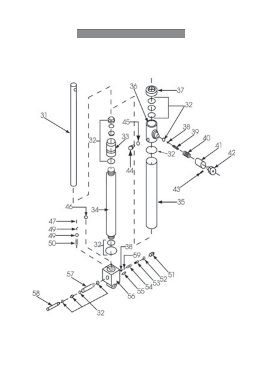
Hydraulic Ram
Page 10

 Loading...