

Page 1
Operating & Maintenance
Instructions
1216
©
Air Compressor
Models: CFP9HND
Part Number: 2090901
Air Compressor
Page 2

- 2 -
Page 3

SPECIFICATIONS
CFP9ND
Part Number 2090901
Engine Type HONDA
Pump Type MK238
Air Receiver size 2.65 litres
Max. output Pressure 100psi
Air Displacement 9cfm
Outlet connectors 1/4” BSP
Dimensions (mm) 520x360x440
Weight (kg) 21
Guarenteed Sound Power Level 96.5dBL
WA
NOTE:
Specifications are correct at the time of going to print.
Clarke International reserves the right to change specifications at any time, as it
sees fit, in the interests of safety or improvement in design.
Copyright: Clarke International, All rights reserved. June,2002
- 3 -
WARNING!
DO NOT ATTEMPT TO ALTER ENGINE SPEED SETTINGS
DOING SO WILL INVALIDATE YOUR GUARANTEE
Page 4

- 4 -
INTRODUCTION
Thank you for purchasing this Clarke Air portable
compressor. The unit is powered by a 5HP Honda engine, a
manual for which, is provided separately. Please refer to
that manual for all matters relating to the engine, ...starting
and stopping procedures, maintenance etc.
Read these safety instructions before using the equipment.
CONTENTS Page
GUARANTEE
This product is guaranteed against faults in manufacture for 12 months
from purchase date. Please keep your receipt as proof of purchase.
This guarantee is invalid if the product has been abused or tampered
with in any way, or not used for the purpose for which it is intended.
The reason for return must be clearly stated.
This guarantee does not affect your statutory rights.
Introduction .................................................................................................................. 4
Guarantee .................................................................................................................... 4
For your Own Safety .................................................................................................... 5
Important General Notes ............................................................................................ 6
General Layout ............................................................................................................ 7
Preparation for Use ...................................................................................................... 8
Starting & Using your Air Compressor ....................................................................... 9
Shutting Down the Compressor ............................................................................... 10
Maintenance .............................................................................................................. 11
Troubleshooting ......................................................................................................... 12
Parts and Service Contacts ...................................................................................... 14
Parts Lists and Diagrams ...................................................................................... 15-17
Declaration of Conformity ........................................................................................ 18
Page 5

- 5 -
FOR YOUR SAFETY
WARNING
As with all machinery, there are certain hazards involved with their operation and use.
Exercising respect and caution will considerably lessen the risk of personal injury.
However, if normal safety precautions are overlooked, or ignored, personal injury to
the operator, or damage to property may result.
It is in your own interest to read and pay attention to the following rules:
General Precautions
ALWAYS
• ensure that all individuals using the compressor have read and fully understand the
Operating Instructions supplied.
• Stop the engine and ensure the pressure is expelled from the air receiver BEFORE carrying
out any maintenance.
• ensure that there is adequate ventilation when spraying flammable materials e.g.
cellulose paint, and keep clear of any possible source of ignition.
• protect yourself. Think carefully about any potential hazards which may be created by using
the air compressor and use the appropriate protection. e.g.Goggles will protect your eyes
from flying particles. Face masks will protect you against paint spray and/or fumes. Ear defenders
will prevent hearing damage caused by load noise.
• consult paint manufacturers instructions for safety and usage, before spraying
• ensure that the air supply is turned off at the machine outlet and all pressurised air from
the machine and other equipment attached to it, is expelled BEFORE disconnecting air
hoses or other equipment.
• make sure that children and animals are kept well away from the compressor and any
equipment attached to it.
• ensure that any equipment or tool used in conjunction with your compressor, has a
safety working pressure exceeding that of the machine.
NEVER
• direct a jet of air at people or animals, and NEVER discharge compressed air against
the skin. COMPRESSED AIR CAN BE DANGEROUS!
• leave pressure in the receiver overnight, or when transporting.
• adjust, or tamper with the safety valves. The maximum pressure is factory set, and clearly
marked on the machine.
• operate in wet or damp conditions. Keep the machine dry at all times. Similarly, a clean
atmosphere will ensure efficient operation. Do not use in dusty or otherwise dirty locations.
• touch the machine until it has cooled down...some of the metal parts can become
quite hot during operation.
• operate your compressor with any guards removed.
Page 6

- 6 -
Fire Prevention
ALWAYS
• switch the engine OFF when refuelling.
• refuel away from any source of heat.
• refuel in a well ventilated area.
NEVER
• overfill the tank, fill to the level specified.
• smoke whilst refuelling and avoid smoking or using a naked flame near the compressor.
• start the engine if there is spilled fuel. Any spillage must be wiped clean and the
compressor allowed to dry before attempting to start the engine.
IMPORTANT General Notes
• NEVER allow anyone, not fully familiar with compressors, to use this equipment.
• DO NOT alter the engine settings....these settings are set at the factory. Should they
need recalibration - consult your Clarke dealer
Exhaust Gas Precautions
WARNING:
Exhaust fumes can be fatal
ALWAYS
• ensure there is adequate ventilation when using the compressor.
• position the compressor so that the exhaust is pointed away from people or animals .
NEVER
• Do not use the compressor indoors or in an enclosed area. (i.e. in a warehouse, tunnel,
well, hold etc.)
Page 7
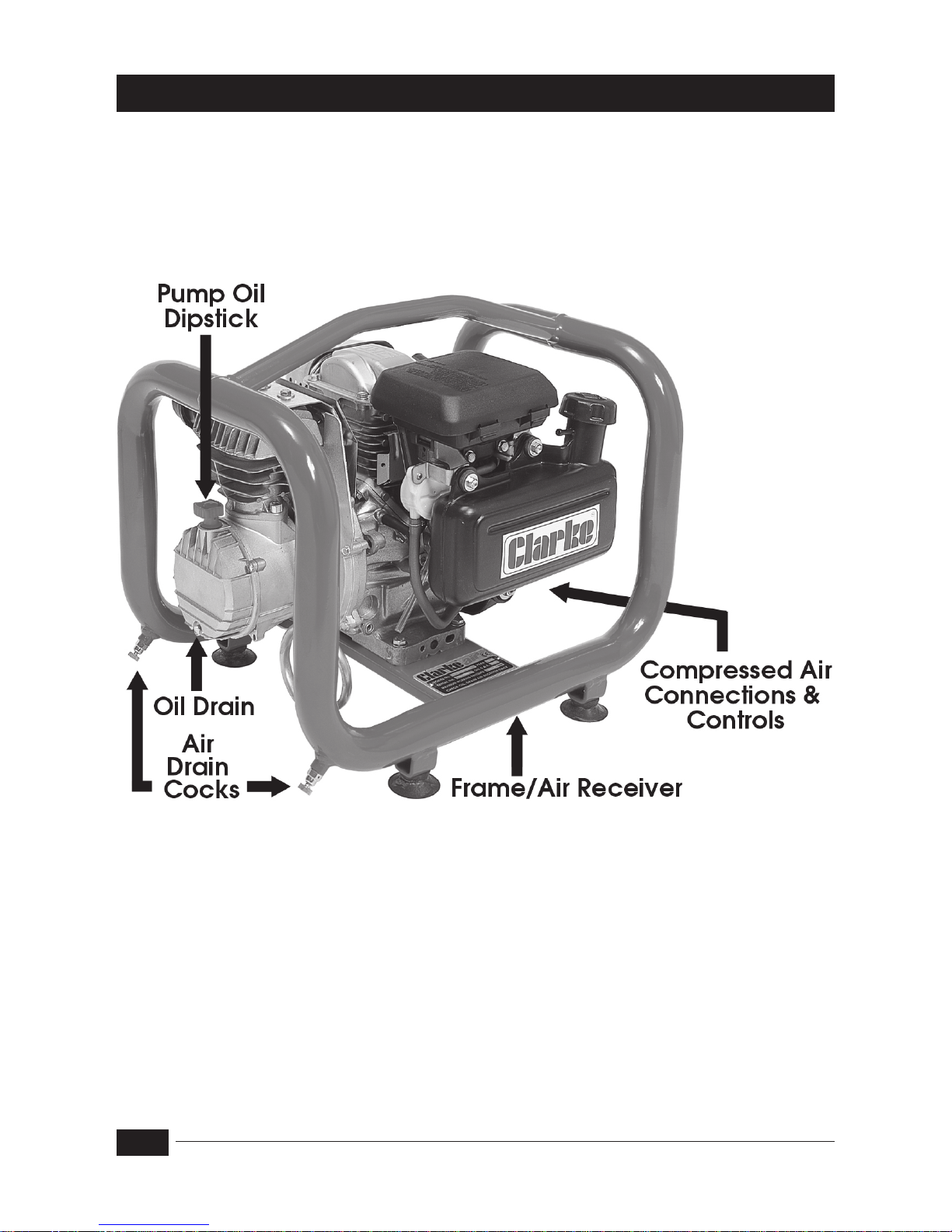
Fig.1
- 7 -
CFP9ND
GENERAL LAYOUT
Page 8

- 8 -
PREPARATION FOR USE
The engine and compressor are supplied without oil inside, a small bottle is
provided in the box and must be added before use (approx 0.6l to the
engine and 0.4l to the pump).
A.Environmental
• Ensure the compressor is sited on a firm level surface.
• Ensure the environment is dry and dust free.
• Ensure there is adequate ventilation for:
a) Air intake to compressor pump
b) Cooling for compressor pump
c) Engine exhaust gases.
B. Engine
• Perform a visual check of components and check oil and fuel levels .
Refer to engine service manual.
C. Pump
• Check
oil level on the Dipstick - to level marked.
D. Fueling
Fill with unleaded petrol, according to the instructions within the engine manual.
• Ensure the fuel tap is set to the required position.
• Ensure The fuel hose and connectors are intact, in perfectly servicable
condition and there is no leakage.
Note : Always use a funnel to fill the fuel tank so as to avoid accidental spillage of
fuel. If fuel is spilled it must be removed from the unit and surrounding area, before
attempting to start the engine.
E. Receiver
• Drain off any condensate, by opening the drain cock (see Fig. 1).
Remember to close the cock when completed.
NOTE: This should be carried out DAILY when the compressor is in constant use.
F. Air Hose & Air Tool
• Attach the air hose to the outlet using an appropriate connector.
• Attach the air tool/spray gun to the air hose...If using snap couplings, use
a whip end, available from your Clarke dealer.
Page 9
STARTING AND USING THE COMPRESSOR
First time startup
NOTE: For first time operation, do not connect the air hose or any tools and proceed
as follows:
1. Start the engine, according to the instructions contained in the engine service
manual, and allow to run for 10 minutes.
2. After a ten minute period, stop the
engine and attach an air hose to
the air outlet and the tool.
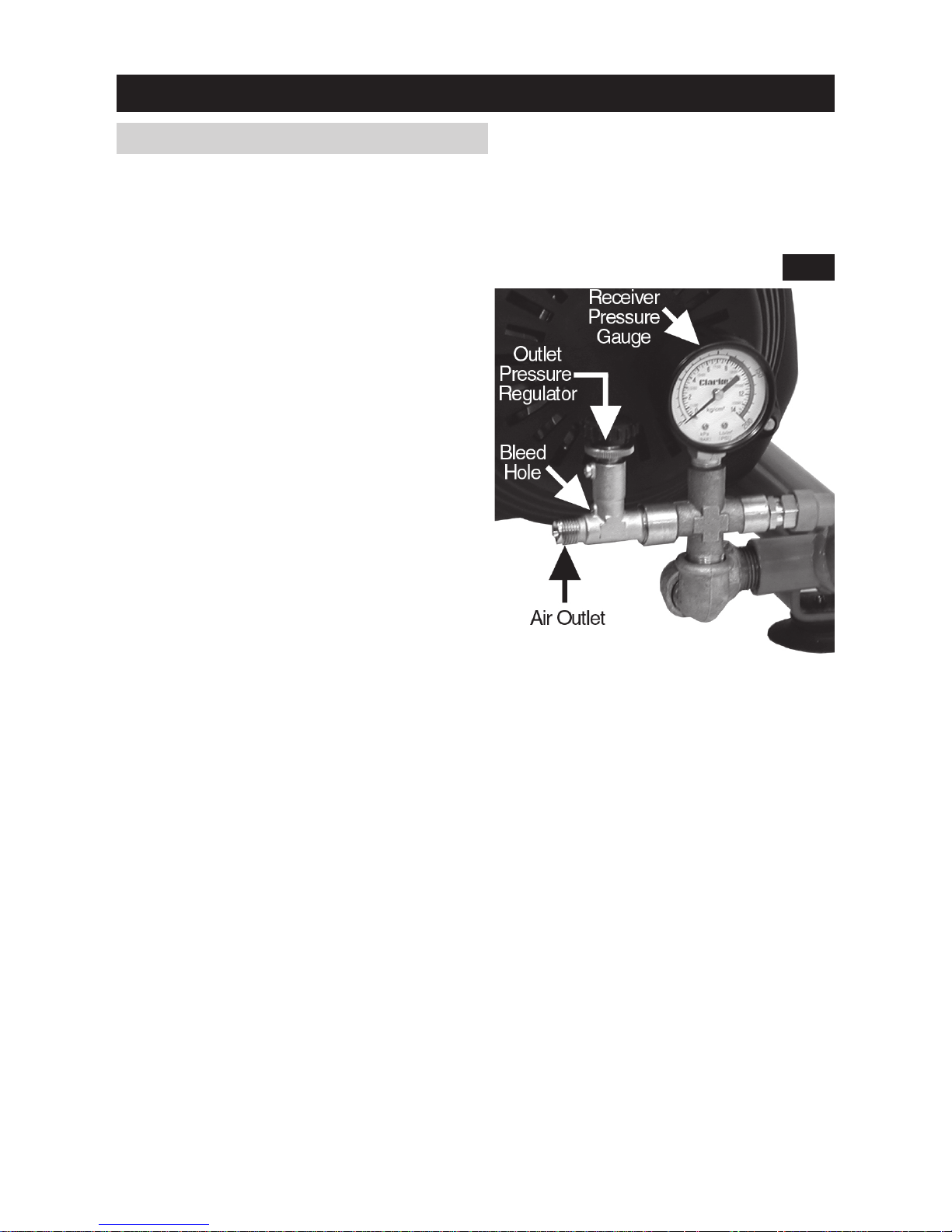
3. Screw the pressure regulator fully
anticlockwise, then restart the
engine and allow presure to build
up in the receiver.
Screw the pressure regulator
clockwise until the pressure,
registered on the Pressure Gauge,
is 100psi.
At this point, check the system for air
leaks. If any are apparent, stop the
engine and operate the tool until the
air pressure is at zero, or open the
drain cocks before rectifying.
NOTE: Air will blow off at the bleed hole when the pressure reaches 100psi,
which is the MAX. operating pressure.
4. With the engine running, turn the pressure regulator so that your desired
pressure is registered on the gauge, and proceed to use the air tool in
accordance with the manufacturers instructions.
When starting subsequently, start the machine as follows:
1. At the begining of the day, open the drain cocks (see Fig.1) and allow any
condensate to drain completely, then close the cocks.
2. Connect the air hose to the air outlet and tool, and set the pressure regulator
to zero pressure (turned fully anticlockwise).
3. Start the engine in accordance with the instructions contained in the engine
service manual, and allow pressure to build up.
4. When the pressure in the receiver has built up and air blows off at the bleed
hole, turn the outlet pressure regulator clockwise so that the desired pressure is
registered on the pressure gauge and proceed to use the air tool/spray gun.
5. Check for air leaks at the tool and connectors...as above, before proceeding.
Fig.2
- 9 -
Page 10

STOPPING THE COMPRESSOR
At the end of the day, stop the engine in accordance with the instructions in the
engine manual, then open the drain cock.
1. Turn the regulator fully anticlockwise.
2. Operate the air tool trigger or operating lever etc., to ensure there is no pressure
in the air line, then disconnect airline and tool.
DO NOT under any circumstances attempt to remove the air tool or disconnect
the air hose until you are satisfied that the pressure has been relieved.
3. Finally, close the drain cock.
Take care not to touch the engine or pump as they remain hot for some time after
use.
- 10 -
REPLACEMENT OILS
Replacement oils are available from your Clarke dealer as follows:
1 litre of Compressor pump oil - Part No. 3050796
1 litre of Engine oil - Part No. 3050852
Page 11
MAINTENANCE
DAILY
a. Drain Air Receiver of any condensate
b. Check engine oil level and top up where necessary. Ensure the dipstick
breather hole is not blocked.
c. Check pump oil level
WEEKLY
a. Clean Pump Filter
1. Turn Pump Filter cover and pull away to reveal paper element. If badly
contaminated, replace. Remove any loose contaminants if any then
replace.
b. Clean the engine cooling fins.
- 11 -
In addition to the above, check the engine manual for service
schedule.
Repairs should only be carried out by a qualified engineer. If problems
occur, contact your Clarke dealer.
6 MONTHLY
Renew pump lubricating oil. and
Make sure the cylider head bolts are
tight (see below)
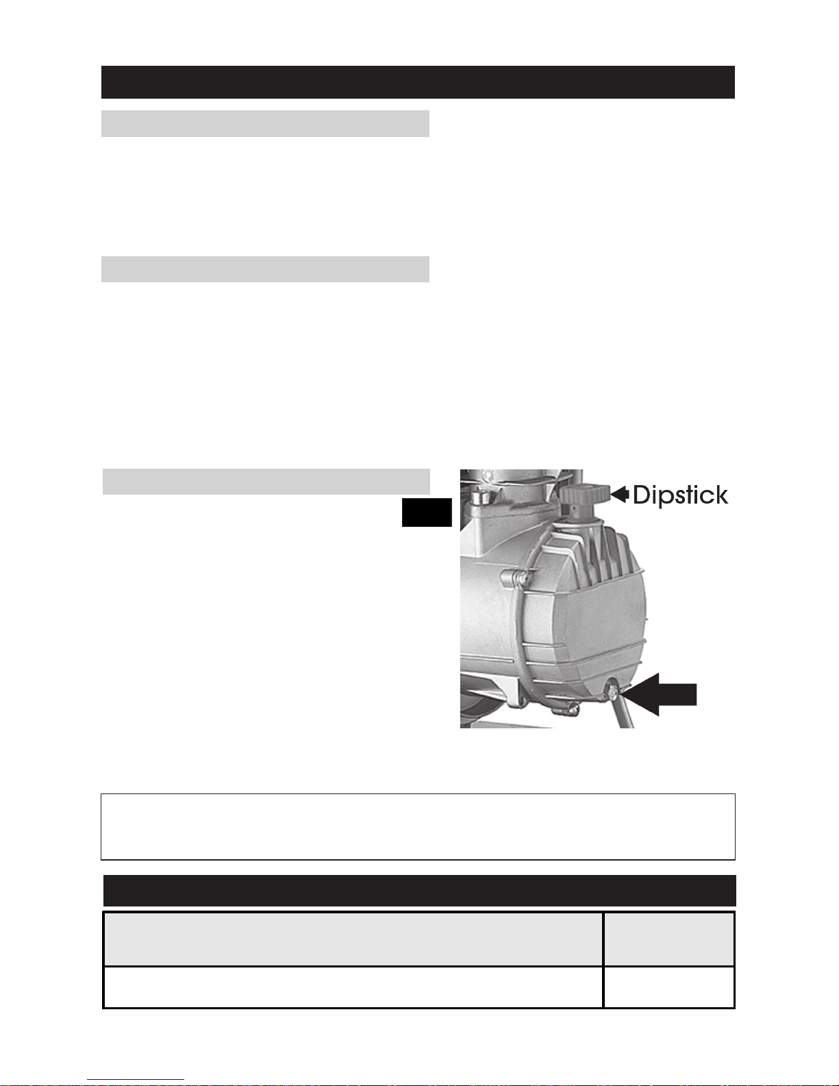
Drain pump by removing the drain
screw (Arrowed in Fig.3).
Replace screw and top up until oil is
level with the mark on the dipstick,
using compressor oil available from your
Clarke dealer as follows: Part No.
3050796
Fig.3
MODEL NUMBER
Torque Vaule
(NM)
PP9ND, CFP9ND 8.8 - 9.3
Torque values for cylinder head bolts
Page 12

TROUBLE SHOOTING CHART
IMPORTANT
1. Any remedial work that may be required must be carried out by a qualified engineer.
2. Switch off the engine before removing any parts from the compressor.
3. Drain the Air Receiver before dismantling any part of the compressor unit’s pressure system.
4. If your compressor develops a fault do not use until the fault has been rectified.
5. For troubleshooting the engine, refer to the engine manual.
- 12-
REMEDY
Stop engine and empty air
receiver. Clean or replace
Load Genie
Thaw Load Genie out (Unit must
be installed in frost-free place).
Have Load Genie serviced or
replaced
Contact Clarke Service
Department
Contact Clarke Service
Department
SYMPTOM
Engine difficult to
start
PROBABLE CAUSE
Load Genie leaking
(compressor unit is on load
during start).
Load Genie valve blocked,
possibly frozen up.
Compressor unit
constantly ‘on load’
Load Genie defective.
Load Genie set at a pressure
higher than the safety
valve’s opening pressure.
Load Genie leaking.
Compressor
constantly ‘on load’
and cannot attain
the working pressure
required.
Suction filter blocked.
Leak between compressor
block and air receiver leaks in
or near air receiver.
Valves blocked by dirt, paint,
dust or choked up.
Inspection cover or drain plug
leaking.
Clean / Change filter.
Tighten connection and
repair leak.
Contact Clarke Service
Department
Empty air receiver and
change seals/plugs.
Pressure gauge defective.
Unit too small in relation to
air consumption.
Change pressure gauge.
Use a larger capacity
compressor
Compressor worn. Have compressor overhauled or
replace it.
Page 13

Unusual noise from
compressor.
Bolts loose.
Flywheel loose.
Unit installed on an unsuitable
base.
Bearings, piston rings or cylinder
worn.
Valve broken.
Compressor
becomes too hot.
Contact Clarke Service
Department
Insufficient ventilation.
Oil level too low (check 2 or 3
times after stopping).
Fault in valves (machine not
stopping).
Non-return valve partly
Clean cooling fins and suction
filter.
Blown head gasket (machine
not stopping).
Dirt on cooling fins or suction
filter.
Unit working at too high a
pressure.
Contact Clarke Service
Department
Clean or that out non return
valve.
Connect to a supplementary
compressor or install a larger
model.
See that sufficient air is supplied to
flywheel or fan of compressor and
that hot air is properly vented.
Fill with oil – see Page 10.
Tighten bolts.
Tighten flywheel.
Move unit to a more solid base.
Contact Clarke Service
Department
Contact Clarke Service
Department
blocked.
Compressor being
overworked and running
continuously.
Contact Clarke Service
Department
- 13 -
Page 14

- 14 -
Large amount of condensation
in air receiver.
Leaks in system
Compressor unit runs
on and off load more
frequently than usual.
Compressor unit runs
‘on load’ when no air is
being used.
Leaks in system.
Compressor’s oil
consumption rising.
Too much oil in compressor.
Cylinder worn.
Oil in the air delivered.
Oil level rises although
no oil has been put in.
Piping installation incorrect.
Compressor taking in air which is
too warm.
Condensation at outlet
points.
Drain off condensation Regularly
(Every day before use).
Locate leaks (by means of soapy
water) and repair.
Locate leaks (by means of
soapy water) and repair.
Intake air filter blocked.
Sump over full.
Leaks around crank case.
Working temperature of
compressor too high because of
insufficient cooling.
Cylinder worn.
Check oil level 2 or 3 minutes after
stopping.
Contact Clarke Service
Department
Increase ventilation to air
compressor.
Reduce oil to correct level.
Compressor over dimensioned.
Intake air filter blocked.
Condensation in oil pump.
Consult your local dealer.
Obtain better fresh-air supply to
compressor.
Clean or replace
Contact Clarke Service
Department
Contact Clarke Service
Department
Clean / Change air filter.
For Spare Parts and Service, please contact your nearest dealer,
or CLARKE International, on one of the following numbers.
PARTS & SERVICE TEL: 020 8988 7400
PARTS & SERVICE FAX: 020 8558 3622
or e-mail as follows:
PARTS: [email protected]
SERVICE: [email protected]
Page 15
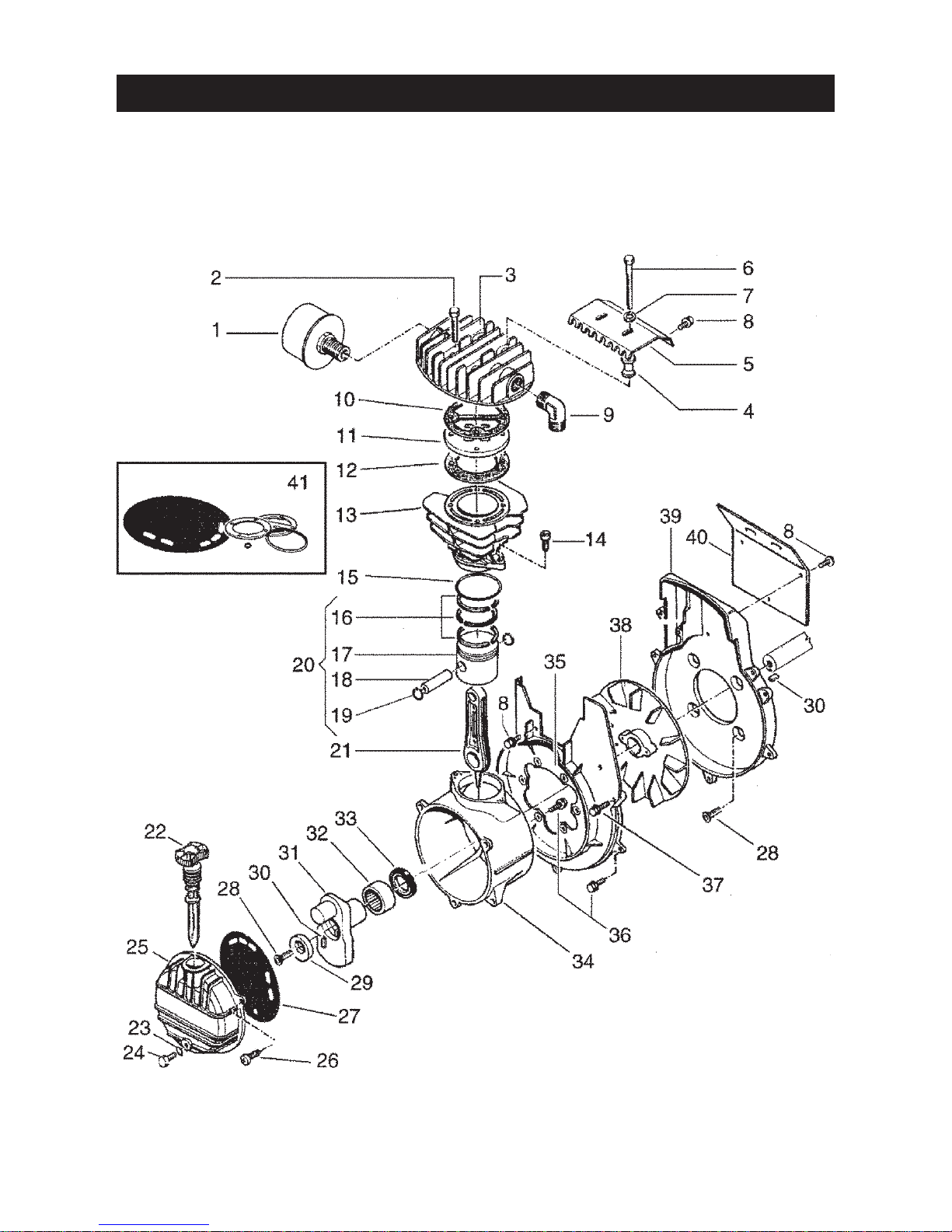
PUMP PARTS
- 15 -
Page 16

No. Description Part No.
1 Air Filter Assy ....................................................................... FN317013000
2 Head Bolt M6x45 ................................................................ FN014002021
3 Cylinder Head .................................................................... FN116001001
4 Spacer ................................................................................. FN116060015
5 Heat Shield ......................................................................... FN116060016
6 Screw M6x70 ...................................................................... FN014002029
7 Washer 6.5x18 .................................................................... FN014005044
8 Screw M5x15 ...................................................................... FN014013042
9 Elbow ................................................................................... FN011015000
10 Gasket ................................................................................. FN116022009
11 Valve plate ......................................................................... FN116022100
12 Gasket ................................................................................. FN116022010
13 Cylinder ............................................................................... FN116022001
14 Screw M8x20 ...................................................................... FN014011064
15 O-Ring ................................................................................. FN010114000
16 Piston Ring Set .................................................................... FN216022002
17 Piston ................................................................................... FN116022004
18 Gudgeon Pin ...................................................................... FN116022040
19 Circlip .................................................................................. FN015001000
20 Piston Complete ................................................................ FN416022004
21 Con-Rod ............................................................................. FN116091021
22 Dipstick ................................................................................ FN012035000
23 Washer ................................................................................ FN010072000
24 Screw M6x10 ...................................................................... FN014013024
25 End Casing ......................................................................... FN016032014
26 Screw ................................................................................... FN014006083
27 Gasket ................................................................................. FN116001025
28 Screw ................................................................................... FN014022001
29 Eccentric............................................................................. FN116060005
30 Key ....................................................................................... FN116060006
31 Crankshaft .......................................................................... FN116060001
32 Bearing ................................................................................
FN033058000
33 Seal ...................................................................................... FN010060000
34 Crankcase .......................................................................... FN116060011
35 Casing ................................................................................. FN116060003
36 Screw M5x20 ...................................................................... FN014013046
37 Screw M5x25 ...................................................................... FN014013045
38 Fan ....................................................................................... FN016060002
39 End Casing ......................................................................... FN116060004
40 Shield ................................................................................... FN116060010
41 Gasket Kit ............................................................................ FN216GA0001
PUMP PARTS
- 16 -
Page 17
- 17-
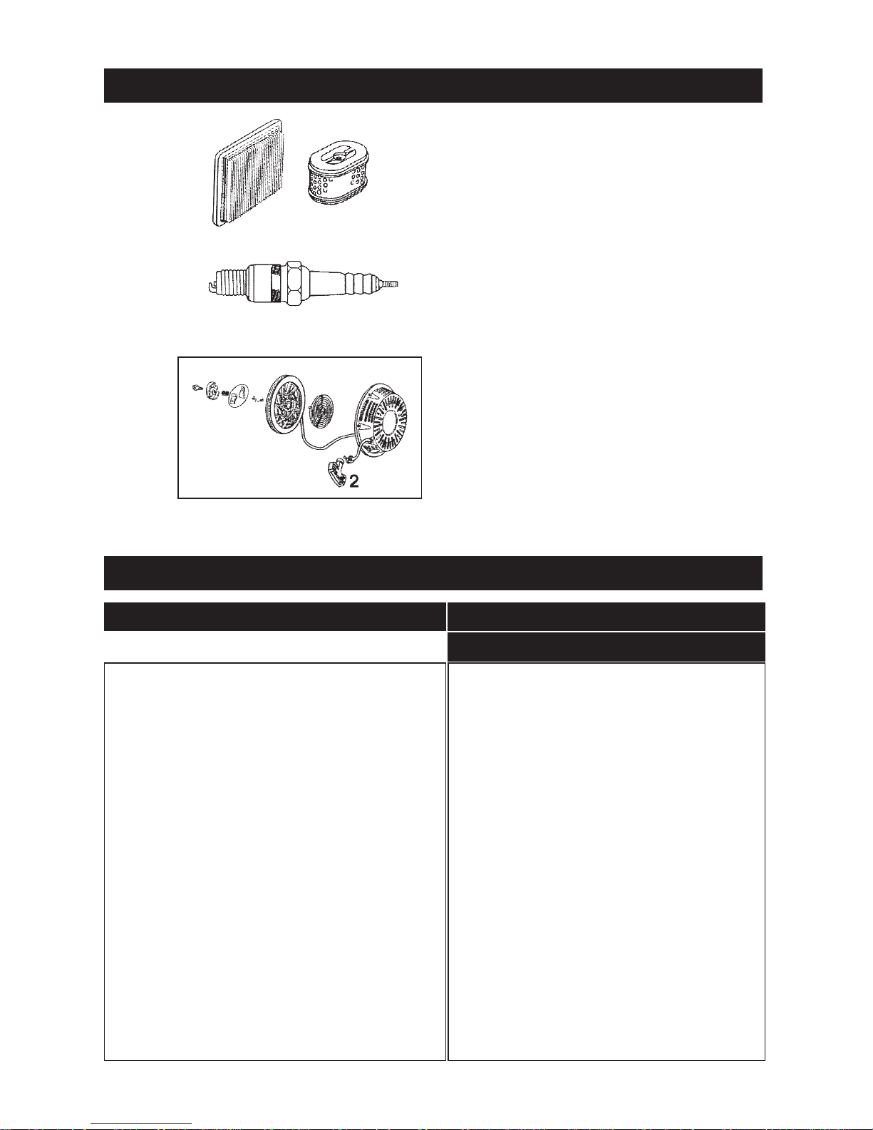
PARTS LIST - ENGINE
HS17211-ZL8-000
HS98079-56846
1.
1. HS28400-ZL8-013ZA
2. HS28462-ZL8003
RECEIVER AND ANCILLIARY PARTS
No. Description Part No.
CFP9ND
1 Pump MK 238 1370005
2 Engine Honda 5HP Contact Spares Department
4 Drain Cock 2000221
5 Bottom Entry Gauge 2000171
6 Safety Valve 2000192
7 Manifold 4-way FN011276000
8 Rubber Foot FN116011006
9 Regulator Assy FN347026000
10 Back Entry Gauge N/A
11 1/2” Load Genie N/A
12 15mm Wheel N/A
13 Wheel Retaining Clip N/A
14 Rubber Foot N/A
15 Mini Filter Regulator N/A
16 Manifold 3-way N/A
Page 18
Page 19

- 19 -
Page 20
 Loading...