

Page 1
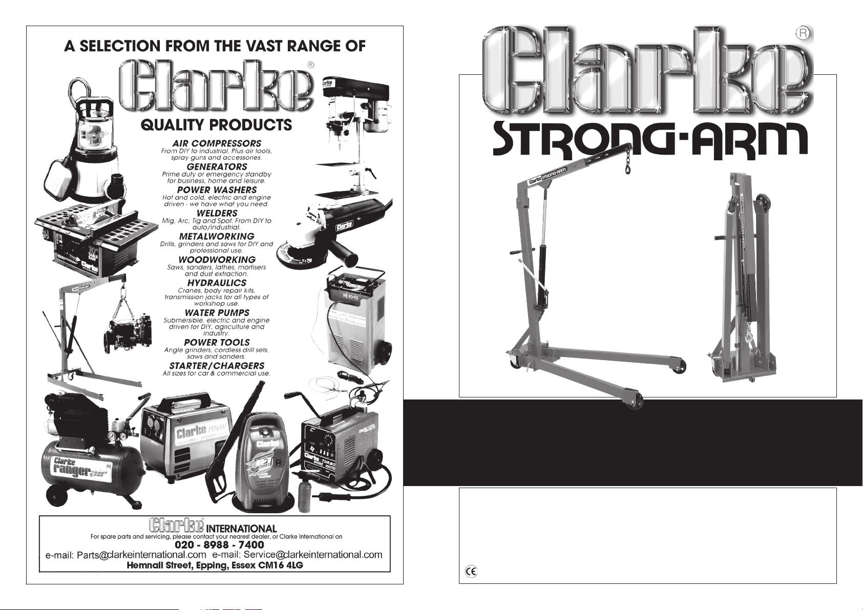
1 TON FOLDING CRANE
1 TON FOLDING CRANE
CFC1000
CFC1000
OPERATION &MAINTENANCE
INSTRUCTIONS
0706
Page 2
SPECIFICATIONS
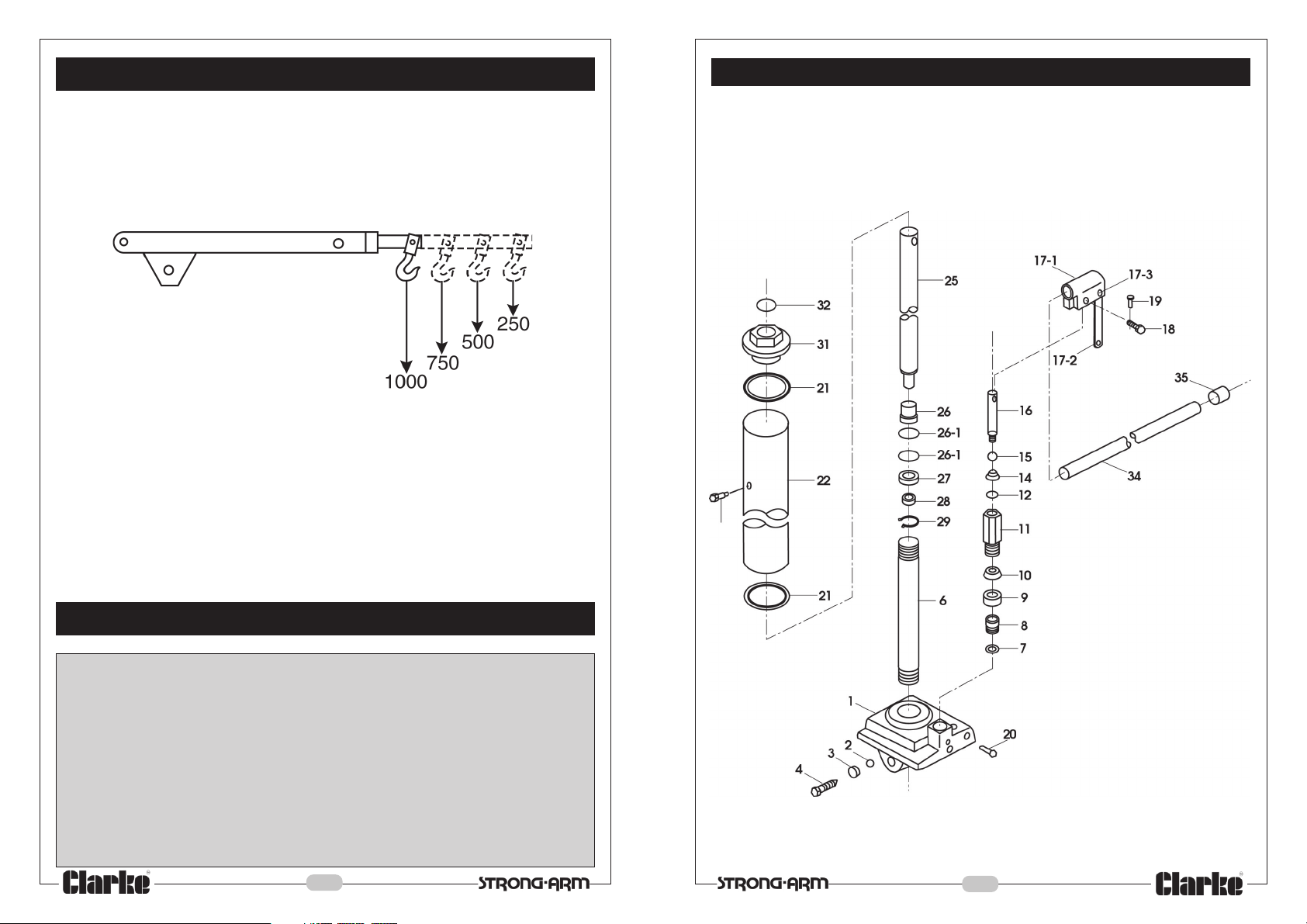
MAXIMUM SAFE WORKING LOADS (kg)
MAXIMUM LIFT HEIGHT - 1920mm
PARTS DIAGRAM - Hydraulic Pump
HYDRAULIC RAM OIL CAPACITY - 450CC
SPARE PARTS & SERVICE CONTACTS
For Spare Parts and Servicing, please contact your nearest dealer, or
CLARKE International, on one of the following numbers.
PARTS - 020 8558 6696 : SERVICE - 020 8556 4443
PARTS & SERVICE FAX - 020 8558 3622
PARTS E-MAIL - [email protected]
SERVICE E-MAIL - [email protected]
2
11
Page 3
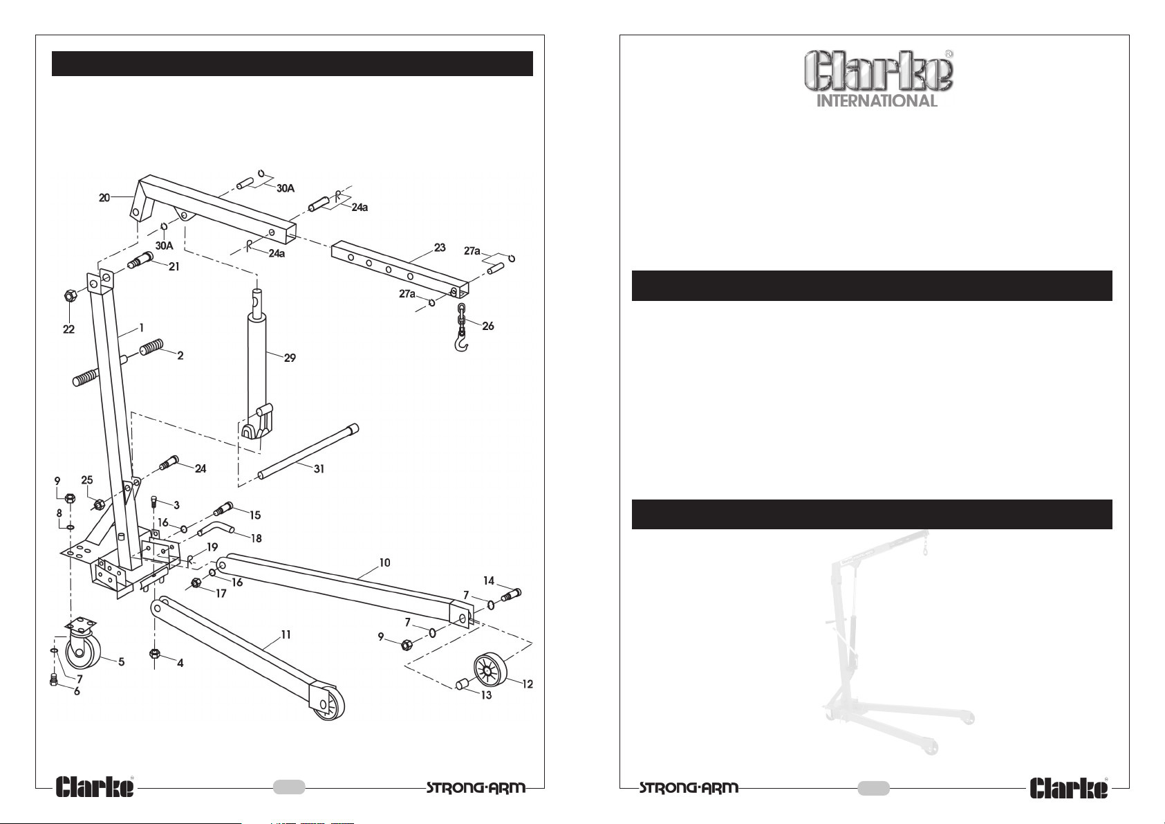
PARTS DIAGRAM - Main Frame
Thank you for purchasing this CLARKE Strong Arm Hydraulic Crane.
Before attempting to use the crane please read this leaflet thoroughly and follow
the instructions carefully, in doing so you will ensure the safety of yourself and that
of others around you, and you can look forward to the crane giving you long and
satisfactory service.
GUARANTEE
This CLARKE product is guaranteed against faulty manufacture for a period of 12
months from the date of purchase. Please keep your receipt which will be required
as proof of purchase.
This guarantee is invalid if the product is found to have been abused or tampered
with in any way, or not used for the purpose for which it was intended.
Faulty goods should be returned to their place of purchase, no product can be
returned to us without prior permission.
This guarantee does not effect your statutory rights.
CONTENTS Page
Specifications - Safe Working Loads ............................................ 2
Spare Parts & Servicing .................................................................. 2
Safety Precautions.......................................................................... 4
Preparation for Use ......................................................................... 5
Operation ........................................................................................ 6
Maintenance .................................................................................. 6
Specifications - Dimensions .......................................................... 8
Parts Lists .......................................................................................... 9
Parts Diagrams ...................................................................... 10 - 11
10
3
Page 4
SAFETY PRECAUTIONS
WARNING
Failure to comply with these rules and precautions, may result in loss of
load, damage to, or failure of the equipment, or even personal injury.
1. DO NOT exceed the load capacity for each jib position (as marked on the
jib). The capacities for each model are shown in tables on the inside front
cover.
IMPORTANT:
If the load capacity decal becomes worn or illegible, contact Clarke
International Spares Division, on 020 8558 6696 for replacement.
2. Ensure that the equipment is correctly assembled, and that all the bolts and
pins are in place and secure.
3. Only use chains, slings, hooks etc. with a rated capacity equal to, or greater
than that of the load. Check that they are secure and will not slip under load.
4. Only use the crane on a solid, flat, level surface which is capable of taking
the load. Avoid moving the crane over rough surfaces.
5. Lower the load as much as possible before moving the crane. Do not use the
crane to transport loads.
6. Do not stand under the load, or above the jib. Be aware that if the load slips
or falls, the jib may rise suddenly.
7. Use appropriate safety equipment, such as protective footwear, when using
this crane.
8. Ensure the crane operator is skilled and trained in both operation and safety
aspects.
9. Always inspect the crane before use to ensure it is in good condition, and
replace any damaged or worn parts.
10. When replacing parts, use only those supplied by Clarke International. Refer
to Parts List.
11. Ensure that the crane is properly maintained, and lubricated at all times, and
that no rust or other forms of corrosion is allowed to weaken any part of the
crane.
12. If the crane has been subjected to an abnormal load or shock, it should be
removed from service immediately and fully inspected by qualified personnel
4
PARTS LIST - MAIN FRAME
No. Description Part No. No. Description Part No.
Mast CFC10001
1
Grip CFC10002
2
Bolt M6x40 CFC10003
3
Nut M6 CFC10004
4
Caster CFC10005
5
Bolt 3/8”x1” CFC10006
6
Spring Washer CFC10007
7
Washer CFC10008
8
Nut 3/8” CFC10009
9
Left Leg CFC10010
10
Right Leg CFC10011
11
Front Wheel CFC10012
12
Bushing CFC10013
13
Bolt 3/8”x 2 3/4” CFC10014
14
Bolt M14x90 CFC10015
15
Washer CFC10016
16
17
Nut M14 CFC10017
18
Lock Pin CFC10018
19
‘R’ Clip CFC10019
20
Boom CFC10020
21
Bolt 3/4”x4 5/8” CFC10021
Nut 3/4” CFC10022
22
23
Boom Extension CFC10023
24a
Pin with 2x‘R’ Clips CFC10024a
25
Nut 5/8” CFC10025
26
Hook with Chain CFC10026
27a
Pin with 2xCirclips CFC10027a
3 Ton Hydraulic Pump CFC10029
29
30a
Pin with 2xCirclips CFC10030a
31
Jack Handle CFC10031
-
Seal Kit (not shown) CFC10032
PARTS LIST - HYDRAULIC PUMP
No. Description Part No. No. Description Part No.
Base CFC301
1
Ball CFC302
2
Seal CFC303
3
Release Valve CFC304
4
Cylinder CFC305
6
Washer CFC306
7
Check Valve Kit CFC307
8
Seal CFC308
9
Washer CFC309
10
Pump Cylinder CFC310
11
O-Ring CFC311
12
Cup Seal CFC312
14
Back-up Ring CFC313
15
Pump Plunger CFC314
16
Handle Sleeve Assy CFC315
17-1
Link CFC316
17-2
Rivet CFC317
17-3
9
18
Pin CFC318
19
Clip CFC319
20
Screw CFC320
Packing CFC321
21
22
Reservoir CFC322
25
Ram CFC323
26
Retainer CFC325
26-1
O-Ring CFC326
27
Cup Seal CFC329
Cup Washer CFC331
28
29
Circlip CFC332
31
Top Nut CFC333
32
O-Ring CFC334
33
Filler Plug CFC335
34
Handle CFC336
Grip CFC337
35
Page 5
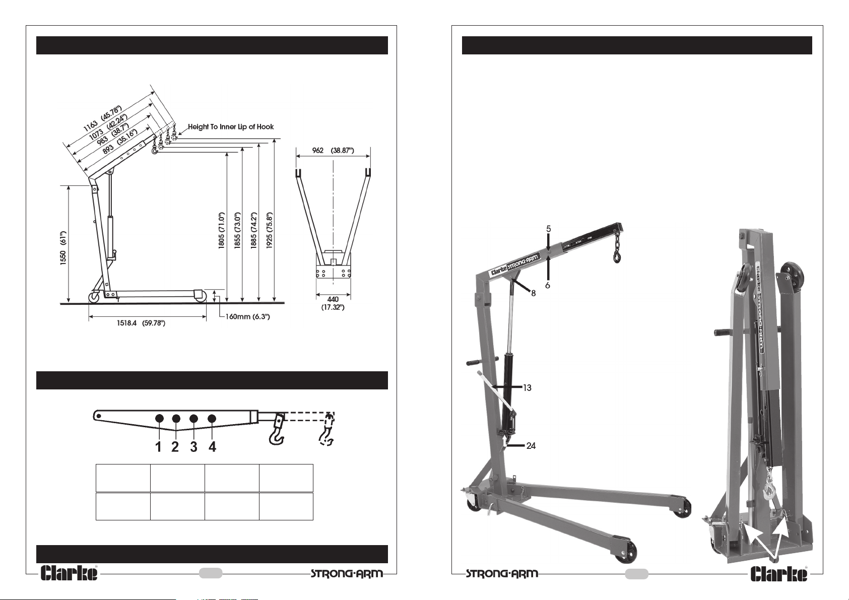
DIMENSIONS (mm)
PREPARATION FOR USE
Unpack the crane on to a clean flat area of hard standing, and visually inspect
components to ensure that no damage was suffered in transit. Should any damage
be apparent, please conrtact your Clarke dealer immediatrely.
The crane is fully assembled at the factory and packed in its ‘folded’ position. To
lower the legs, proceed as follows:
1. With an assistant taking the weight of the leg, pull out the ‘R’ clip, which secures
the leg locking pin, (arrowed in Fig.1a), then pull out the locking pin.
2. Lower the leg to the ground.
3. Replace the leg locking pin, through the hole provided in the frame, through
the leg and out through the bracket, so that the leg is locked in the downward
position, remembering to replace the ‘R’ clip.
The Hydraulic pump operating handle is housed in a bracket on the side of the
main mast.
MAXIMUM SAFE WORKING LOADS (kg)
1234
1000 750 500 250
Fig.1
Fig.1a
HYDRAULIC RAM OIL CAPACITY - 450CC
8
5
Page 6
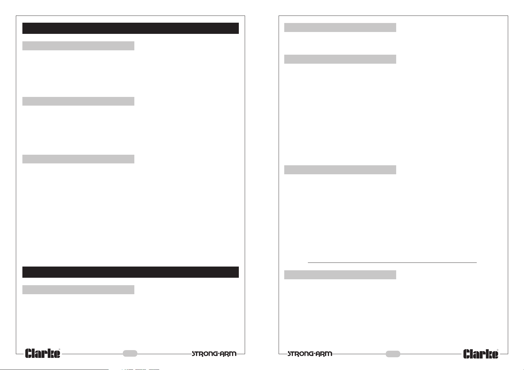
OPERATION (Numbers Refer to Fig.1)
A. Raising the jib
1. IMPORTANT: Ensure the hook is directly above the point of lift, and the point of
lift is directly above the centre of gravity of the load.
2. Close the valve (24) by turning it fully clockwise using the end of the pump
handle. Return the pump handle to the pump linkage and pump the handle
(13) to reach the desired height.
B. Lowering the jib
Turn the valve (24) VERY SLOWLY anticlockwise, using the end of the pump handle
and the jib will lower.
NOTE:
The more the valve knob is turned, the faster the rate of descent. Be extremely
careful when lowering heavy loads.
C. Jib Extension
B. Every Three Months
Pivot pins should be removed and inspected for wear, deformation, cracks. If any
deformation or cracks are apparent, the pin should be renewed.
C. Annually
The crane should be fully inspected annually by a competant person.
1. All pivot pins should be removed, inspected and greased before
reinsertion or replacement.
2. Check for cracks and deformation of components.
3. Check wheels and castors to ensure they move freely without undue wear to
their bores, and that the wheels are not cracked or damaged in any way.
4. Check the hydraulic ram operation and check oil level. (see below).
6. Remove completely, any rust or corrosion and repaint to prevent further
corrosion.
7. Ensure that all decals and warning notices are in place and perfectly
legible.
The jib is extended by first raising it to a horizontal position, then removing the ‘R’
clip (6), securing the locating pin (5), and withdrawing the pin.
Reposition the arm extension to the desired length, and replace the pin ensuring
the ‘R’ clip is firmly in place.
NOTES:
a. During transit or storage, it is possible that an air pocket may have developed
within the hydraulic ram, and the ram action may therefore appear to be
‘spongy’. As the ram is self bleeding, any air will be dispelled and the ram
action normalised by fully raising and lowering the jib a few times.
b. Should the jib not reach its full height, the oil level should be checked, as
described in the Maintenance section.
MAINTENANCE
A. Before Use
1. Always visually inspect the crane before use, to ensure that all parts are
correctly located and secure. Check for hydraulic leaks, signs of damage or
worn parts and check the wheels and castors for serviceability.
Do not use the crane unless it is perfectly serviceable.
2. A slight dampness on the ram is normal, but where leakage is apparent, the
ram seals must be renewed......Consult your Clarke dealer.
D. Periodically
It may be necessary from time to time to top up the Hydraulic oil level, as follows.
1. Lower the jib to its lowest position, and remove the Ram to Jib locating pin
(item 8, Fig1).
2. Rest the ram against the Mast whilst raising and propping the jib.
3. Remove the vent plug (Parts list item 69) from the ram, and using an oil can,
filled with hydraulic oil (see below), slowly top up the oil until it begins vent
plug.
We recommend that the hydraulic oil is changed after every 100 hours of
operation.
NOTE: Top up using Clarke hydraulic oil (part number 3050830).
E. General
1. After use, wherever possible, store the crane with the jib in its lowest position,
regardless of whetherr the legs are folded or not. This not only relieves the
hydraulic ram, but also prevents any possibility of corrosion to the ram.
2. Do not leave the crane in the open, exposed to the elements. Keep under
cover.
3. DO NOT remove the pump Pressure Relief Valve, or attempt to adjust the
pump settings.
6
7
 Loading...