

Page 1
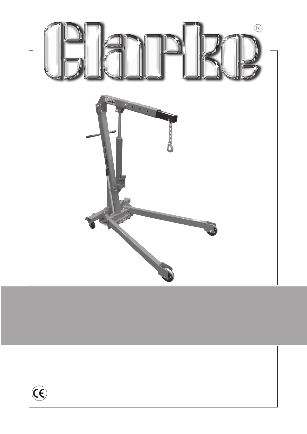
FOLDING CRANE
MODEL No: CFC100
Part No: 7611005
ASSEMBLY INSTRUCTIONS
LS0216
Page 2
INTRODUCTION
Thank you for purchasing this CLARKE folding crane.
Before using the crane, please read this instruction manual thoroughly and
carefully follow all directions given. This is for your own safety and for that of
others around you, and will also help you achieve long and trouble free service
from your crane.
GUARANTEE
• This product is guaranteed against faulty manufacture for a period of 12
months. Please keep your receipt as proof of purchase.
• This guarantee is invalid if the product is found to have been abused or
tampered with in any way, or not used for the purpose for which it was
intended.
• Faulty goods should be returned to their place of purchase, no product
can be returned to us without prior permission.
• This guarantee does not effect your statutory rights.
SPECIFICATION
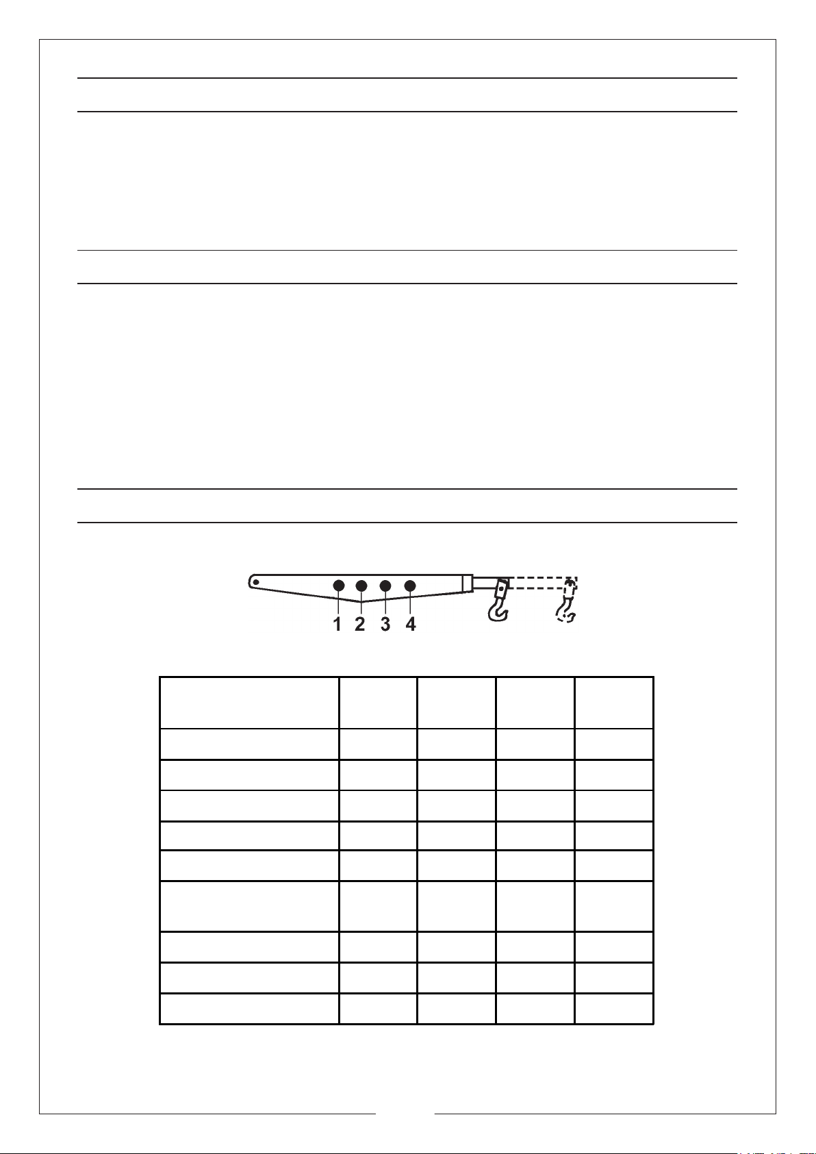
Lifting Capacity (kg) 1000 750 500 250
Max. Lift Height (mm) 1815 1880 1945 2010
Max.Jib Length (mm) 900 990 1080 1170
Overall Width (mm) 1030
Width Between Legs
(mm)
Position1Position2Position3Position
4
890
Height of Legs (mm) 150
Weight (kg) 74
Part Number 7611005
2
Page 3

SAFETY INFORMATION
WARNING FAILURE
RESULT IN LOSS OF LOAD, DAMAGE TO, OR FAILURE OF THE EQUIPMENT, OR
EVEN PERSONAL INJURY.
1. Always read instructions before setting up the equipment and before use
2. Always inspect the crane before use to ensure it is correctly assembled and in
good condition and replace any damaged or worn parts
3. When replacing parts, use only those supplied by Clarke International. Refer
to Parts List on pages 4-5.
4. Never exceed the safe working load capacities specified on the jib for each
position (as marked on the jib).
IMPORTANT: If the load capacity decal becomes worn or illegible, contact Clarke
Parts and service department, on 0208 988 7400 for replacement.
5. Only use chains, slings, hooks etc. with a rated capacity equal to, or greater
than that of the load. Check that they are secure and will not slip under load.
6. Always lock the jib and legs into position before lifting a load.
7. Only use the crane on a flat, solid, level surface that is capable of sustaining
the weight of the load.
8. Lower the load as much as possible before moving the crane. Do not use the
crane to transport loads.
TO COMPLY WITH THESE RULES AND PRECAUTIONS, MAY
9. Use appropriate safety equipment, such as protective footwear, when using
this crane.
10. Ensure the crane operator is skilled and trained in both operation and safety
aspects.
11. Do not allow the load to swing or drop suddenly whilst moving or lowering
12. If the crane has been subjected to an abnormal load or shock, it should be
removed from service immediately and fully inspected by qualified personnel
13. Ensure that the crane is properly maintained, and lubricated at all times, and
that no rust or other forms of corrosion are allowed to weaken any part of the
crane.
14. Do not use around children or untrained persons.
15. This is a heavy unit (74kg) take care when lifting.
16. Do not use this crane to lift people.
17. Do not work under any raised load.
STORAGE - VERY IMPORTANT
See separate section on page 9
3
Page 4
PARTS SUPPLIED
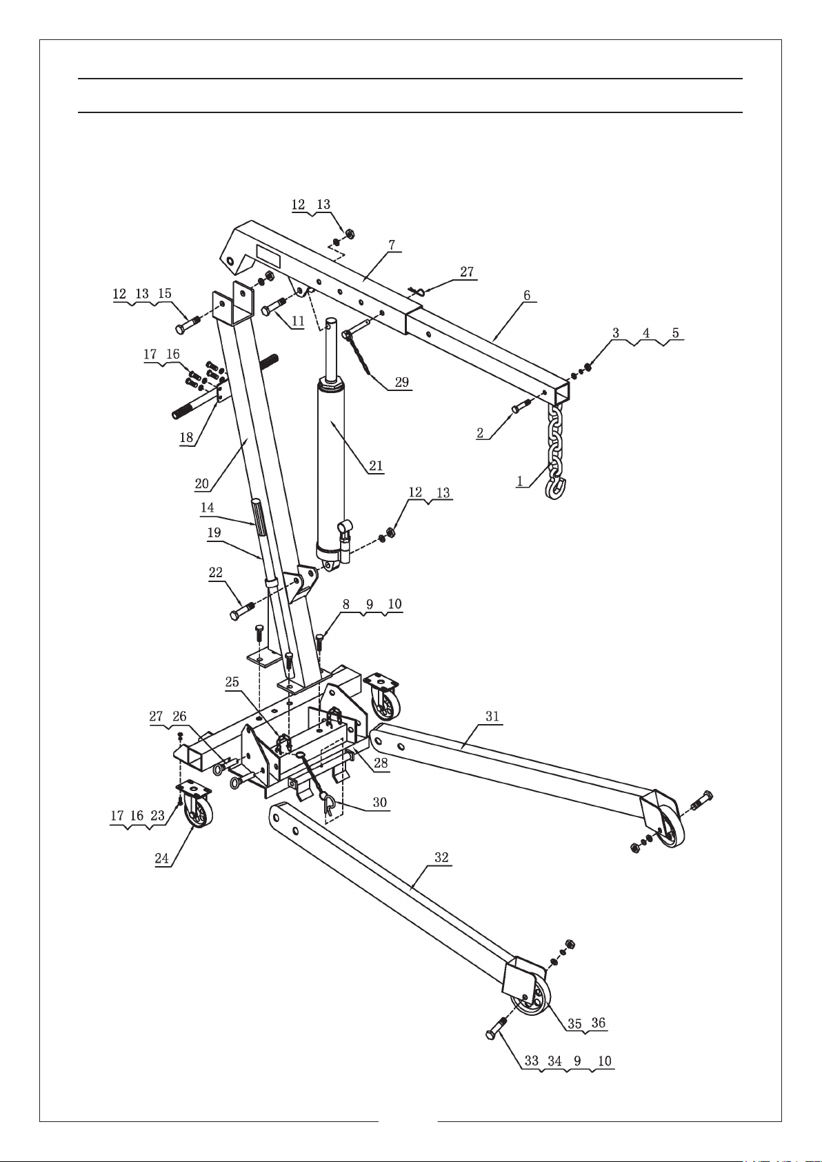
Unpack the crane on to a clean flat area of hard standing, and visually inspect
components to ensure that no damage was suffered in transit. Should any
damage be apparent, please contact your Clarke dealer immediately.
4
Page 5
PARTS SUPPLIED
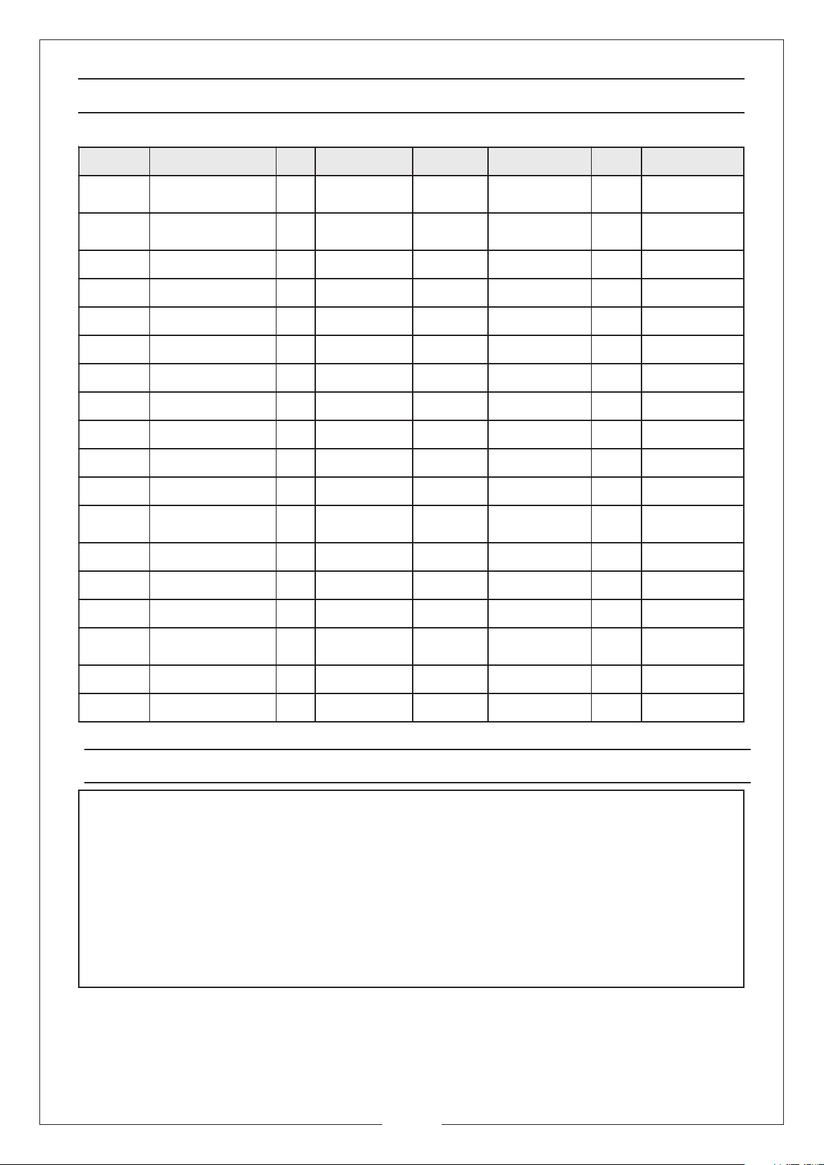
rebmuN noitpircseD .ytQ rebmuNtraP rebmuN noitpircseD .ytQ rebmuNtraP
1
208x21MtloB120001CFCNS02
321ØrehsaWtalF130001CFCNS12maR112001CFCNS
421ØrehsaWkcoL140001CFCNS2209x61MtloB122001CFCNS
521MtuN150001CFCNS328MtuN832001
6noisnetxEbiJ160001CFCNS42rotsaC"½3242001CFCNS
7biJ170001CFCNS52niahC252001CFCNS
8001x41MtloB580001CFCNS62niPkcoL462001
941ØrehsaWtalF790001CFCNS72pilCR572001CFCNS
0141MtuN701001CFCNS82esaB182001CFCNS
1107x61MtloB111001CFCNS92ylbmessAniP19
2161ØrehsaWtalF321001CFCNS03
3161MtuN331001CFCNS13geLtfeL113001CFCNS
41pirGe
ldnaH341001CFCNS23geLthgiR123001CFCNS
kooH&niahC
ylbmessA
110001CFCNS91eldnaHpmuP191001CFCNS
troppuSniaM
tsoP
RytuDyvaeH
niahC+pilC
102001CFC
103001CFCNS
NS
CFCNS
CFCNS
2001CFCNS
51011x61MtloB151001CFCNS3358x41MtloB233001CFCNS
6102x8MtloB2161001CFCNS43
718ØrehsaWkcoL2171001CFCNS53leehWnorI"5253001CFCNS
81eldnaH181001CFCNS63gnihsuB263001CFCNS
L
8Ø
rehsaWkco
243001CFCNS
SPARE PARTS AND SERVICING
Please contact your nearest dealer, or CLARKE International, on one of the following numbers.
PARTS & SERVICE TEL: 020 8988 7400
PARTS & SERVICE FAX 020 8558 3622
or e-mail as follows:
PARTS: [email protected]
SERVICE: [email protected]
5
Page 6
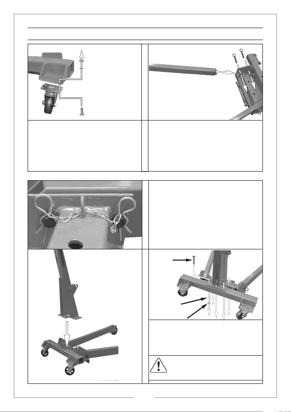
ASSEMBLY
1. Fit the castor (24) to the base (28)
using 4 bolts (16), lock washers
(17) and nuts (23).
2. Repeat for both castors.
3. Slide the right leg (32) into the
base (28) as shown, line up the
holes and insert two lock pins
(26).
4. Repeat the procedure for the left
leg (31).
5. Secure the pins using the R clips
(27) and small chains (25).
• Make sure the chain passes
through the loop shown on the
left.
6. Attach the main support post (20)
onto the base assembly (28) using
five bolts (8), five washers (9) and
five nuts (10).
CAUTION: PLEASE TAKE CARE AS
THE MAIN SUPPORT POST MAY
TOPPLE OVER .
6
Page 7
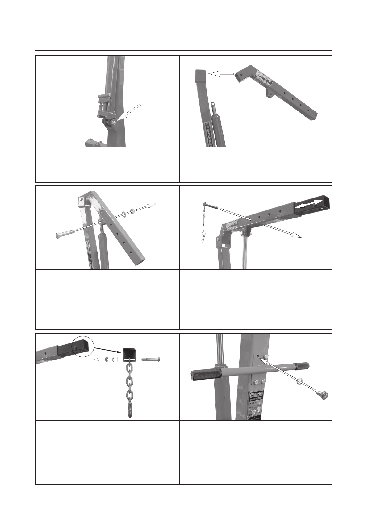
ASSEMBLY
7. Fix the ram (21) into position using
bolt (22), washer (12) and nut (13).
9. Connect the top of the ram (21) to
the jib (7) as shown using bolt (11),
washer (12) and nut (13).
Note: The ram may require extending
to facilitate assembly, see page 8
8. Attach the jib (7) to the top of the
main support post (20) using bolt
(15), washer (12) and nut (13).
10. Slide the jib extension (6) into the
jib (7), use the pin assembly (29) to
lock it into the required position.
The pin is secured by inserting the
attached R clip into the small hole at
the other end of the pin.
11. Pass the last link of the chain and
hook assembly (1) through the
hole on the bottom of the jib
extension (6). Secure the chain
using bolt (2), washer (3), lock
washer (4) and nut (5).
12. Connect the handle (18) to the
rear of the main support post (20)
using four bolts (16), and four lock
washers (17).
7
Page 8
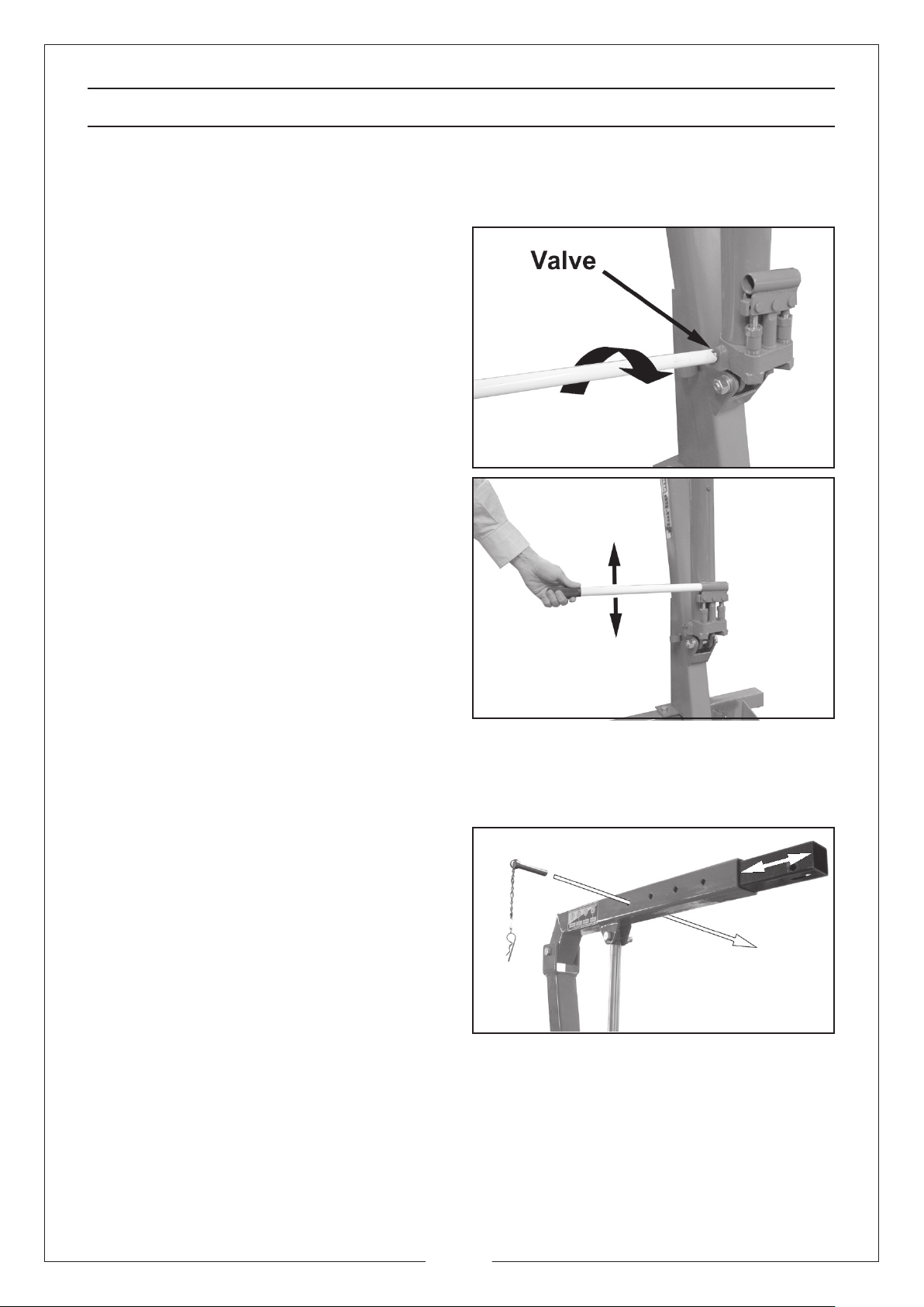
OPERATION
RAISING THE JIB
IMPORTANT: Make sure that the hook is directly above the point of lift, which in
turn is directly above the centre of
gravity of the load.
1. Use the end of the pump handle
(19) to close the valve by turning it
fully clockwise.
• It should be hand tight, do not
overtighten.
2. Return the pump handle (19) to the
pump linkage and pump the
handle until the crane reaches the
desired height.
LOWERING THE JIB
1. Use the end of the pump handle
(19) to turn the valve anticlockwise VERY SLOWLY.
• The speed of lowering the load is controlled by how much you turn the
valve.
EXTENDING THE JIB
1. Raise the jib to a horizontal position.
2. Remove the locating pin assembly
(29), and withdraw the pin.
3. Reposition the jib extension to the
desired length.
4. Replace the pin assembly (29)
ensuring the ‘R’ clip is firmly in place.
NOTES:
a. During transit or storage, it is possible that an air pocket may have
developed within the hydraulic ram, and the ram action may therefore
appear to be ‘spongy’. As the ram is self bleeding, any air will be dispelled
and the ram action normalised by fully raising and lowering the jib a few
times.
b. Should the jib not reach its full height, the oil level should be checked, as
described in the Maintenance section.
8
Page 9
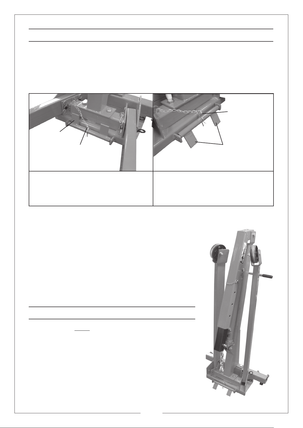
STORAGE
ALWAYS get adult assistance when folding the crane into its storage
configuration.
TO STORE THE CRANE.
1. When storing the crane, the stabiliser must be locked in the down position.
You may need to tilt the crane back slightly to position the stabiliser correctly.
R-Clip (30)
Stabiliser
R-Clip (30)
During use
The stabiliser should be placed in the
up position and locked in place using
the heavy duty R Clip (30)
2. With an assistant supporting the crane, pull out the ‘R’ clip (27), which secures
the front leg lock pin, then pull out the lock pin.
3. Raise the leg up to the storage position.
4. Replace the leg lock pin (26), through the hole
provided in the frame so that the leg is locked in
the up position,
5. Replace the ‘R’ clip to secure the locking pin.
6. The pump handle (19) is housed in a bracket on
the side of the main support post (20).
7. Once the crane is folded use extreme care when
moving it to the storage location.
The stabiliser should be placed in the
down position and locked in place
using the heavy duty R Clip (30)
During storage
Stabiliser
STORAGE WARNINGS
1. The crane MUST be firmly secured to a wall or fixed
location when not in use.
2. Use a strong strap or chain or suitable restraint to
prevent any accidental movement.
3. Test that the crane is firmly secured before leaving
it in its storage location.
Alternatively you can lay the crane down and store it
flat.
Always secure the jib in its lowest position.
9
Page 10
MAINTENANCE
GENERAL
1. Always, store the crane with the jib in its lowest position, This prevents any
possibility of corrosion to the ram.
2. Do not leave the crane in the open or exposed to the elements. Keep under
cover.
3. Do not attempt to adjust or tamper with the ram assembly, there are no
serviceable parts. Contact your Clarke service department for any servicing.
BEFORE USE
1. Always visually inspect the crane before use, to ensure that all parts are
correctly located and secure. Check for hydraulic leaks, signs of damage or
worn parts and check the wheels and castors for serviceability.
2. A slight dampness on the ram is normal, but where leakage is apparent, the
ram seals must be renewed. Consult your Clarke service department.
EVERY THREE MONTHS
1. Each pin and bolt should be removed and inspected for wear, deformation
or cracks. If any are apparent, the pin or bolt should be renewed.
2. Check the hydraulic ram operation and check the hydraulic oil level. (see
below).
ANNUALLY
The crane should be fully inspected annually by a competent person.
1. Check wheels and castors to ensure they move freely without undue wear to
their bores, and that the wheels are not cracked or damaged in any way.
2. Remove any rust or corrosion and repaint to prevent further corrosion.
3. Ensure that all decals and warning labels are in place and perfectly legible.
HYDRAULIC OIL
It may be necessary from time to time to top up the
Hydraulic oil level, as follows.
1. Lower the jib to its lowest position, and remove
the bolt that joins the ram (21) to the Jib (7).
2. Rest the ram against the main support post and
raise and prop up the jib (7). Use a cable or
similar ensure the ram does not drop.
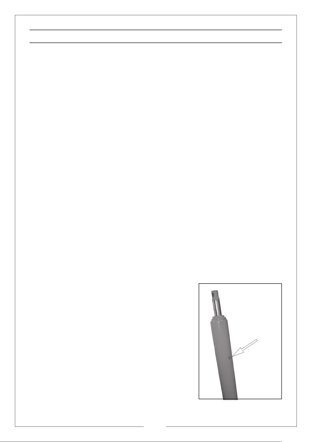
3. Remove the vent plug from the side of the ram.
Vent plug
4. Top up the oil until it is level with the hole. Then
replace the vent plug.
• We recommend that the hydraulic oil is
changed after every 100 hours of operation.
NOTE: Top up using Clarke hydraulic oil (part
number 3050830).
• Do not mix different types of oil.
10
Page 11
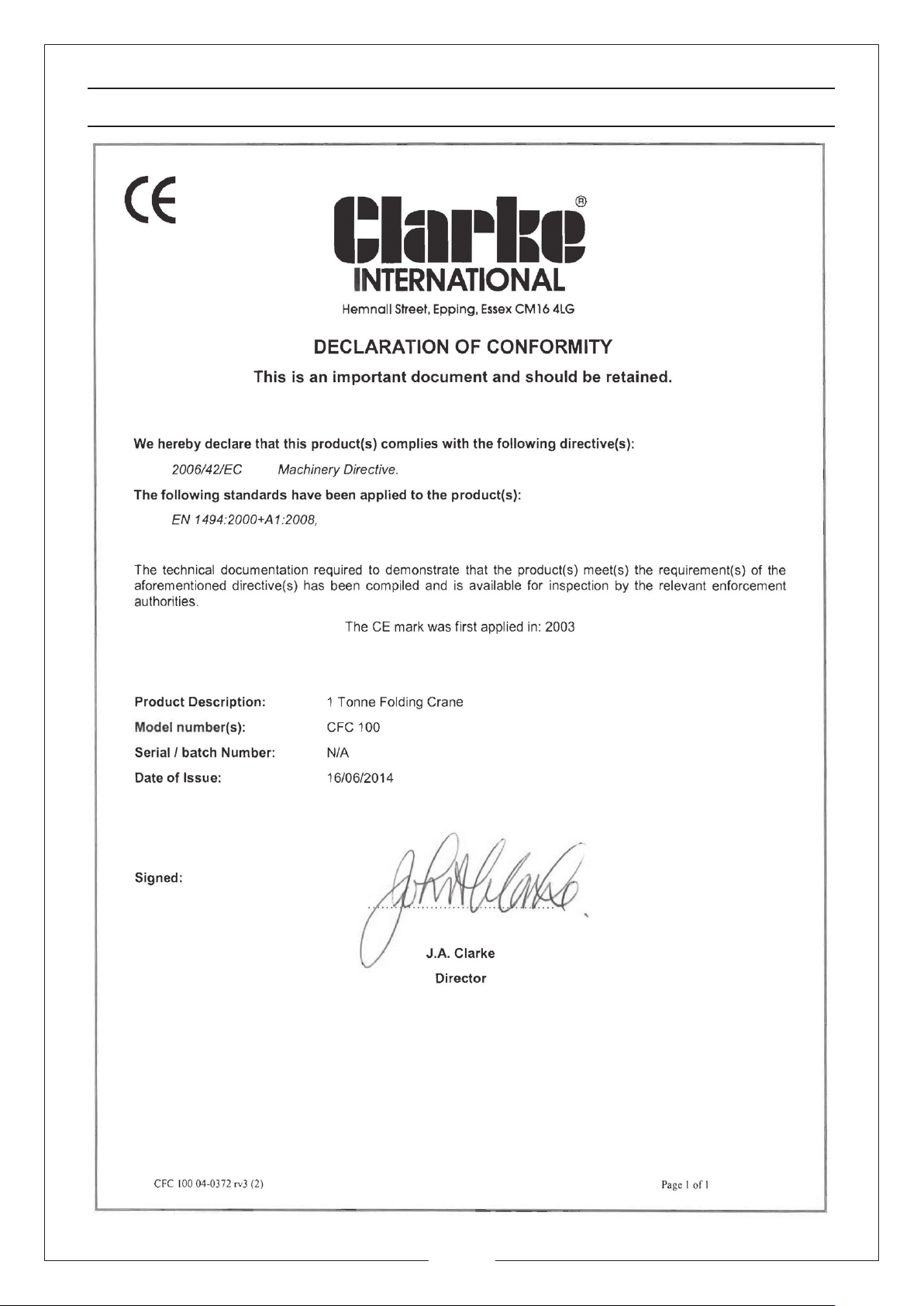
DECLARATION OF CONFORMITY
11
Page 12

12
 Loading...