


CONCRETE MIXER
Models CCM125C & CCM126
Part Nos: 3400840 & 3400842
ASSEMBLY & MAINTENANCE
INSTRUCTIONS
GC514

INTRODUCTION
Thank you for purchasing this CLARKE Concrete Mixer.
Before attempting to operate the machine, it is essential that you read this
manual thoroughly and carefully follow all instructions given. In doing so you
will ensure the safety of yourself and that of others around you, and you can
also look forward to the product giving you long and satisfactory service.
GUARANTEE
This CLARKE product is guaranteed against faulty manufacture for a period of
12 months from the date of purchase. Please keep your receipt as proof of
purchase.
This guarantee is invalid if the product is found to have been abused or
tampered with in any way, or not used for its intended purpose.
Faulty goods should be returned to their place of purchase, no product can
be returned to us without prior permission.
This guarantee does not effect your statutory rights.
ENVIRONMENTAL PROTECTION
Through purchase of this product, the customer is taking on the
obligation to deal with the WEEE in accordance with the WEEE
regulations in relation to the treatment, recycling & recovery and
environmentally sound disposal of the WEEE.
In effect, this means that this product must not be disposed of with general
household waste. It must be disposed of according to the laws governing
Waste Electrical and Electronic Equipment (WEEE) at a recognised disposal
facility.
2
CONTENTS
INTRODUCTION .................................................................................. 2
GUARANTEE ........................................................................................ 2
ENVIRONMENTAL PROTECTION ......................................................... 2
PARTS & SERVICE CONTACTS .............................................................2
TECHNICAL SPECIFICATION ...............................................................3
GENERAL SAFETY PRECAUTIONS .......................................................4
ELECTRICAL CONNECTIONS .............................................................. 5
UNPACKING & PRE-ASSEMBLY CHECK ..............................................6
ASSEMBLY ........................................................................................... 7
MAINTENANCE ...................................................................................12
COMPONENT PARTS LIST AND DIAGRAM ......................................... 13
DECLARATION OF CONFORMITY....................................................... 15
TECHNICAL SPECIFICATION
erutaeF C521MCC 621MCC
rebmuNtraP04800432480043
thgieWgk36gk36
mm)hxwxl(snoisnemiD0421x017x08110621x017x0221
rotoMesahp1,zh05,v0
gnitarrewoprotoMPH3/1PH3/1
tnerruCdaoLlluFspma46.1spma2.4
yticapacgnixiMsertil521sertil521
deepSmurDmpr13mpr13
levelrewopdnuoSAWLBd0.19AWLBd2.29
Please note that the details and specifications contained herein, are correct at the
time of going to print. However, CLARKE International reserve the right to change
specifications at any time without prior notice.
32esahp1,zh05,v011
3

GENERAL SAFETY PRECAUTIONS
1. ALWAYS Keep the work area clean and well lit. Floors should always be kept
clear. Cluttered or dark areas invite accidents.
2. ALWAYS keep children and bystanders away while operating a power tool.
Distractions can cause loss of control.
3. ALWAYS stay alert & do not use a machine while you are tired or under the
influence of medication or alcohol.
4. ALWAYS wear suitable protective clothing and eye protection including
industrial gloves, ear defenders & approved impact resistant safety glasses.
(Eye glasses are NOT safety glasses)
5. NEVER over-reach. Keep your proper footing and balance at all times to
enable better control of the machine in unexpected situations.
6. NEVER stand on the machine. Injury could occur from a fall.
7. ALWAYS store machines out of reach of children.
8. ALWAYS read and become familiar with the entire operating manual.
9. NEVER allow persons unfamiliar with this manual to operate this machine.
10. ALWAYS maintain the machine with care and keep it clean for best / safest
performance.
11. NEVER use this machine if any part is damaged. Have it inspected and
repaired by a competent technician.
12. NEVER modify this machine in any way. Use it ONLY for the purpose for which
it is designed.
13. ALWAYS keep guards in place when the machine is in operation.
14. ALWAYS ensure the electrical cable is fully protected and there is no danger
of damage from equipment or materials. Always Inspect the cable before
use and replace if any damage is apparent.
15. ALWAYS disconnect the machine from the power supply when not in use,
and before carrying out any maintenance.
16. NEVER leave the machine running unattended or leave machine until it
comes to a complete stop.
17. ALWAYS keep your hands well clear of the rotating drum at all times. NEVER
put your hands inside the drum when the machine is switched ON.
18. NEVER wear jewellery or loose clothing that could be snagged by any part
of the rotating drum.
19. NEVER load the drum when the machine is switched off. Always switch on
and ensure the drum is rotating.
20. ALWAYS have power tools serviced by your CLARKE dealer, using only identical
replacement parts. This will ensure the safety of the machine is maintained.
4

ELECTRICAL CONNECTIONS
CCM125C
Connect the power lead to a standard 230 Volt (50Hz) electrical supply
through an approved BS1363, 13amp plug or a suitably fused isolator switch.
CCM126
Connect the power lead to a suitable 110 Volt (50Hz) electrical supply
through an approved plug or a suitably fused isolator switch. If using a
portable 110 Volt transformer make sure it has a rated capacity sufficient to
take the load of the motor - See Data Plate.
Both models:
We recommend that this machine is connected to the mains supply through
a Residual Current Device (RCD).
WARNING! THIS APPLIANCE MUST BE EARTHED
IMPORTANT: The wires in the mains lead are coloured in accordance with the
following code:
Green & Yellow - Earth
Blue - Neutral
Brown - Live
As the colours of the flexible cord of this appliance may not correspond with
the coloured markings identifying terminals in your plug proceed as follows:
• Connect GREEN & YELLOW wire to terminal marked with a letter “E” or
Earth symbol “ ” or coloured GREEN or GREEN & YELLOW.
• Connect BROWN wire to terminal marked with a letter ‘L’ or coloured RED.
• Connect BLUE wire to terminal marked with a letter ’N’ or coloured BLACK.
CCM125C
If this appliance is fitted with a plug which is moulded onto the electric cable (i.e.
non- rewirable) please note:
1. The plug must be thrown away if cut from the electric cable. There is a
danger of electric shock if it is subsequently inserted into a socket.
2. Never use the plug without the fuse cover fitted.
3. Should you wish to replace a detachable fuse carrier, ensure that the
correct replacement is used (as indicated by marking or colour code).
Replacement fuse covers can be obtained from your local dealer or most
electrical stockists.
4. The fuse in the plug must be replaced with one of the same rating
(13amps) and this replacement must be ASTA approved to BS1362.
If in doubt, consult a qualified electrician....DO NOT attempt repairs yourself.
5

UNPACKING & PRE-ASSEMBLY CHECK
Remove all components from the packing case and lay them out neatly so
that they can be identified and checked for any possible damage during
transit. Should any component be found to be damaged, please contact
your CLARKE dealer immediately.
Check the components against the following list, referring to Fig 1.
A. Rubber Sealing Ring
B. Upper Drum
C. Lower Drum Assembly
D. Locking Plate
E. Axle Assembly
F. Motor Support Plate
G. Drum Collar (2 pcs)
H. Clamp Plate
I. Spacer Plate
J. Fixings Pack(nuts,bolts washers)
ACD
K. Pulley Alignment Rod
L. Front Leg
M. Wheels (pair)
N. Mixing Blades (2 pcs)
O. Hand Wheel
P. Frame
Q. Drive Pulley
R. Drive Belt
S. Inner Motor Cover
T. Motor c/w End Cove
r
Fig. 1
E
M
B
F
G H I J K L
N
O P
Q
RST
6

ASSEMBLY
N
otes:1. The letters in brackets refer to Fig.1
2. Unless otherwise stated, all nuts, bolts, washers and fixings are
supplied in the fixings pack (J). This also contains the Clamp
Plate (H) and Spacer Plate (I).
3. Tools required will include a X-headed screwdriver and
spanners / sockets of 6,10,12,13,14 & 17mm sizes.
IMPORTANT
F
or maximum safety and to ensure the adjustments are carried out correctly,
assistance should be employed during the assembly operation.
THE STAND
1. With the frame (P) lying on its
side, attach the axle assembly (E)
as shown in fig 2, using two M8 x
60 bolts, together with nut, spring
and flat washers.
2. Turn the frame over and attach
the front leg (L) as shown.
3. Stand the assembly upright and
slide a wheel on to each stub
axle, followed by a large flat
washer and secure them using
the split pins.
Fig. 2
THE LOWER DRUM
1. With the help of an assistant if
required, lower the lower drum
assembly (C), onto the side
supports of the stand as shown in
fig 3, so that the bearing blocks at
each end, slot into the channels
provided by the side supports.
• The larger diameter shaft should
be at the Leg end of the stand.
2. Use an M8 x 60 bolt with flat
washer at each fixing position,
and secure using a nut and spring
washer.
Fig 3
7

3. Slide the circular locking plate (D), over
the large diameter shaft, at the leg end of
the frame, with the rim facing inwards, as
shown in Fig.4. (Note that the centre hole
in the plate is cut away to allow the plate
to pass over the circlip on the shaft).
Secure with two M8 x 25 bolts, each with a
nut, flat washer and spring washer.
THE HANDWHEEL
1. Insert the spring into its holder in the centre
of the wheel spar. Hold it in place, and
slide the handwheel over the shaft so that
the shaft retains the spring, and the holes
in the bracket Y, (Fig 4), line up with the
drilled hole in the shaft.
2. Insert the M10 x 65mm bolt with flat
washer at the bolt head, and screw on
two nuts. Screw the first nut up against the bracket firmly, but not so tightly
so as to prevent the handwheel from pivoting about the bolt. Lock the
nut in this position by screwing up the second nut tightly.
Fig. 4
NOTE: The handwheel must be allowed to pivot about the bolt so that
the lugs on the bracket (Y) can be engaged or disengaged from
the slots in the locking plate.
THE MIXING BLADES
1. Bolt the mixing blades in place loosely as
shown in Fig 5.
• Two holes are provided at the base of
the drum into which an M8 x 20 bolt may
be inserted from the inside the drum.
These bolts are supplied attached to the
blades and are provided with a flat and
leather washer. The leather washer
should contact the drum.
2. A spring washer and a nut should be
threaded on loosely onto the bolt from
the outside. Do not tighten these yet.
Fig. 5
THE UPPER DRUM
1. Position the rubber sealing ring on to the rim of the lower drum, ensuring
the holes in the seal and those of the drum line up.
2. Push an M6 x 16 cross headed screw through the rim from below and twist
through the corresponding hole in the sealing ring.
• The screws will hold the sealing ring loosely in position and not drop out.
8

3. With assistance if required, rest the upper drum so that it sits on the rim of
the lower drum. Rotate it so that the screws enter the fixing holes from
below. Look to see that the holes for the upper mountings of the mixing
blades also line up with those in the upper drum.
4. When all fixings are correctly lined up, use the screws, nuts and flat
washers to gently pull the upper and lower drum halves together, gripping
the seal between them. Look inside the drum to check that the seal is
sitting correctly in position.
NOTE: It is desirable practice for the screws to be fitted from above,
therefore, remove them one at a time and re-fit the correct way,
adding a spring washer at each position.
5. Finally, tighten all the fastenings progressively.
6. Secure the mixing blades to the upper drum by inserting the dome
headed coachbolt, through the hole in the drum from the outside,
ensuring the square portion of the bolt seats in the square hole in the
drum. The leather washer should bear against the drum.
7. Secure the mixing blade on the inside using a flat washer, spring washer
and nut.
8. Finally, ensure top and bottom mixing blade mountings are tight.
THE MOTOR COVER, MOTOR SUPPORT & DRIVE PULLEY
Note: To restrain it in transit, the
motor will be found bolted
to the inner cover with
suitable packing materials.
Remove the bolts which are
used for this.
1. Bolt the inner motor cover (S) to
the bearing block using two M8 x
25mm bolts with flat washers at
the bolt heads, from within the
inner cover, and spring washers
with nuts to the rear of the
bearing block. Leave the nuts
loose at this stage.
2. Attach the motor support plate
(F), as shown in Fig. 6, by inserting
four M6 x 65mm bolts, through
the holes in the support plate (F),
the slotted holes in the inner
cover (S), and the spacer, which
is inserted between the back of
the inner cover, and the frame
(see fig 6).
9
Fig. 6

The bolts extend through the securing plate which locates behind the
frame, each bolt being secured using a spring washer and nut. The nuts
should be left loose at this stage.
NOTE: The spacer and securing plate are of similar construction,
however, the LARGER of the two should be used as the SPACER.
3. When all four bolts are fitted, centralise the inner cover (S) on the support,
then fully tighten the two bolts securing it to the bearing block.
4. Remove any adhesive tape used to secure the key to the drive shaft
during transit and slide the drive pulley (Q) on to the shaft, having lined up
the key and keyway. Ensure the grub screw in the hub of the pulley faces
outwards (see Fig 7).
• If the fit is unduly tight, check that the hole in the pulley is smooth and
clear of any excess paint and clean up if necessary using a round file. It
may be necessary to drive the pulley on to the shaft using a soft faced
hammer, until the central boss is roughly flush with the end of the shaft.
Lock the pulley in this position by tightening the grub screw.
THE DRIVE BELT & MOTOR
1. Wrap the drive belt around the drive pulley, seating it into the groove.
2. Place the motor on the support plate with the motor pulley resting on the
drive belt. Fit four M8 x 25mm bolts through the slotted holes in the motor
mounting bracket and through those in the motor support plate, ensuring
flat washers are in place against the bolt head. Fit a flat washer, followed
by a spring washer and nut to each of the bolts from below, leaving the
nuts loose at this stage.
NOTE: During this operation, take care not to
strain the power cable which is
attached to the motor cover.
3. Slide the motor support plate (F) upwards
until the motor and support plate are sitting
level and secure in this position temporarily,
by nipping up two of the four nuts securing
the support plate to the frame, (do not fully
tighten them). The motor, belt and support
plate should be as shown in Fig 7.
4. Hold the steel guide rod so that it rests
across the face of the upper pulley as
shown in Fig 7, as near to the centre of the
pulley as possible. Gently adjust the position
of the motor and motor support plate until
the back of the motor pulley just comes into
contact with the rod.
5. Check the distance between the back of
the motor mounting bracket and the back
10
Fig. 7

edge of the motor support plate as
shown in fig 8, to ensure the motor is
square to the support and frame. Secure
Fig. 8
the motor in this position by fully
tightening the four mounting bolt/nuts.
• This adjustment ensures that the two
pulleys are in alignment and it is
important that time is taken to ensure it is
correct, otherwise premature failure of
the drive belt could occur.
6. Slacken the two nuts, previously nipped
up, which secure the motor mounting
plate to the frame, then push down on the motor so that tension is applied
to the belt. The tension is correct when there is approximately ½"
movement at the centre of the belt when using moderate thumb
pressure. When satisfied, secure the motor support plate by evenly
tightening the nuts behind the securing plate.
NOTE: It is important that the belt tension and pulley alignment are
correct, to ensure satisfactory operation of the machine and to
prevent excessive wear and premature failure of the drive belt.
7. To attach the outer cover to the inner cover it is first necessary to attach
the support chain, using the cross headed screws attached with washers
and nuts, to the holes provided in the inner and outer cover. The outer
cover is then secured to the inner cover using similar cross headed screws
with nuts and washers.
NOTE: The chain is a safety feature to prevent undue strain on the power
cable when the outer cover is removed, and it is important that it
is attached at all times.
DRUM COLLAR
NOTE: The drum collar is a safety feature, and must ALWAYS be in place.
DO NOT operate the machine with the collar removed.
1. Before the collar is attached, it is recommended that a layer of grease
(not supplied) is applied to the drive teeth under of the rim of the drum.
2. Attach the drum collar as shown in Fig 9. The two halves must bolted
together using three M6 x 20mm
bolts with a flat washer, spring
washer and nut, and each half is
secured to a bracket at either
side with a single M6 x 10mm
bolt with a flat and spring
washer. (Bolts may be supplied
already fitted to the collar).
11
Fig. 9

CARE AND MAINTENANCE
STARTING WORK
Inspect the power cable and ensure it is completely free from damage and
is not in danger of being damaged by vehicles, equipment or other
operations taking place on the work site.
Important: Do not load the drum when the machine is switched off. Always
set the machine running before filling.
AFTER USE
It is essential that the machine is hosed down thoroughly with clean water,
being sure to remove all traces of cement mix especially from around the
mixing blades, Take care to prevent water from entering the motor housing
and if necessary, wrap a polythene sheet or bag over it during cleaning.
PERIODICALLY
It is recommended that the collar occasionally be removed and grease
smeared on the drive teeth underside of the lower rim. Ensure the collar is
replaced correctly.
After extensive use, inspect the paintwork and remove any rust that may be
apparent before touching up where necessary with a rust resistant paint.
It may be benificial to inject a few drops of light oil into the lubrication points
located on top of the bearing blocks and rotate the drum to ensure
distribution of oil around the bearing surface.
STORAGE
By removing the higher of the two
bolts connecting the legs to the frame,
the leg/axle assemblies can be
hinged, so as to collapse the machine
to low level as shown in Fig 10. The
lower bolts will need to be slackened
off for this.
The wheels can still be used for
mobility in this position. Always replace
the bolts loosely in their normal
positions during storage.
CAUTION; OWING TO THE WEIGHT OF THE MACHINE, TWO PEOPLE WILL
BE REQUIRED TO UNBOLT THE SUPPORTING COMPONENTS AND SAFELY
LOWER THE MIXER TO THIS POSITION.
Fig 10
12

COMPONENT PARTS DIAGRAM
13

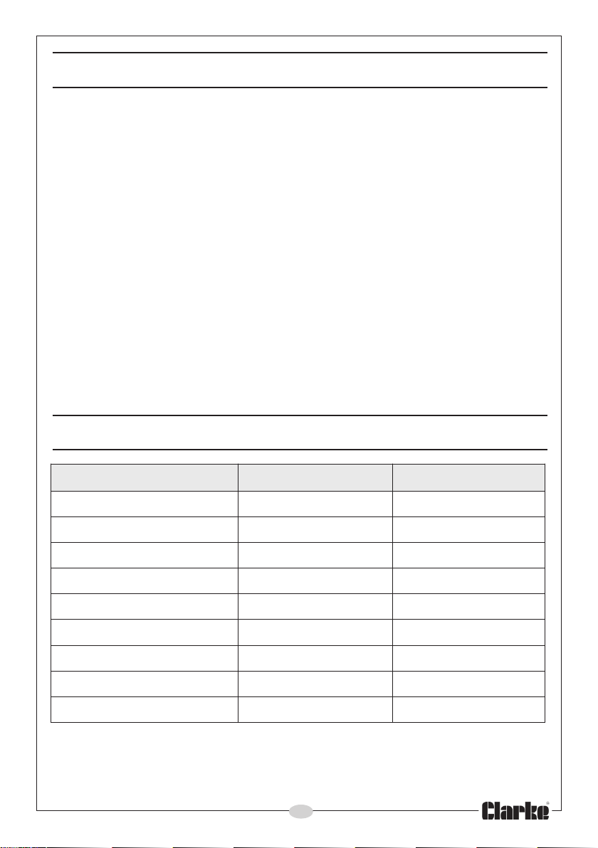
COMPONENT PARTS LIST
No. Description Qty Part No.
1 Frame 1 SD0001
2 Axle Assembly 1 SD0002
3 Leg 1 SD0003
4 Wheel 4 SD0004
5 Large Washer 2 SD0005
6 Split Pin 2 SD0006
7 Motor Support Plate 1 SD0007
8 Spacer/Plate 6mm 2 SD0008
9 Motor Assy - 230V 1 SD0009
9 Motor Assy - 110V 1 SD0009A
10 Motor Pulley 1 SD0010
11 Key 1 SD0010
12 Switch Assembly 1 SD0012
13 Outer Cover 1 SD0013
14 Cable Grommet 1 SD0014
15 Drive Pulley 1 SD0015
16 Grub Screw 1 SD0016
17 Inner Cover 1 SD0017
18 Circlip 4 SD0018
19 Flat Bearing Washer 4 SD0019
20 Bearing Block 2 SD0020
21 Drive Shaft 1 SD0021
The following items are the nuts, bolts, and washers packed separately and which
may be locally procured from any hardware or DIY store, or from your CLARKE
dealer quoting the part numbers given.
No. Description Qty Part No.
22 Parallel Key 1 SD0022
23 Circlip 1 SD0023
24 End Cap 1 SD0024
25 Bearing Set 1 SD0025
26 Pinion 1 SD0026
27 Yoke Assembly 1 SD0027
28 Lower Bearing Plate 1 SD0028
29 Bearing Set 1 SD0029
30 Bearing Plate Upper 1 SD0030
31
Locking Plate 1 SD0031
32 Hand Wheel 1 SD0032
33 Spring 1 SD0033
34 Lower Drum 1 SD0034
35 Sealing Ring 1 SD0035
36 Upper Drum 1 SD0036
37 Collar Assembly 1 SD0037
38 Drive Belt 1 SD0038
39 Mushroom Head Bolt 2 SD0039
40 Leather Washer 4 SD0040
41 Mixing Blade 2 SD0041
42 Support Chain 1 SD0042
43 Steel Guide Rod 1 SD0043
a. M5 x 10 Slot Rd Hd 4 3044701
b. M6 x 20 Hex Bolt 6 3044501
c. M6 x 16 Cross Hd 6 3044705
d. M6 x 65 Hex Bolt 4 3044702
e. M8 x 25 Hex Bolt 8 7101107
f. M8 x 60 Hex Bolt 6 3044703
g. M10 x 65 Hex Bolt 1 3044704
h. M5 Nut 4 3040608
i. M6 Nut 16 3040600
j. M8 Nut 14 3040601
k. M10 Nut 1 3040602
l. 5mm Flat Washer 4 3040574
m. 6mm Flat Washer 24 3040575
n. 8mm Flat Washer 18 3040576
o. 10mm Flat Washer 1 3044577
p. 5mm Spr. Washer 4 3040595
q. 6mm Spr. Washer 22 3040581
r. 8mm Spr. Washer 14 3040582
14

DECLARATION OF CONFORMITY
15

 Loading...