

Page 1
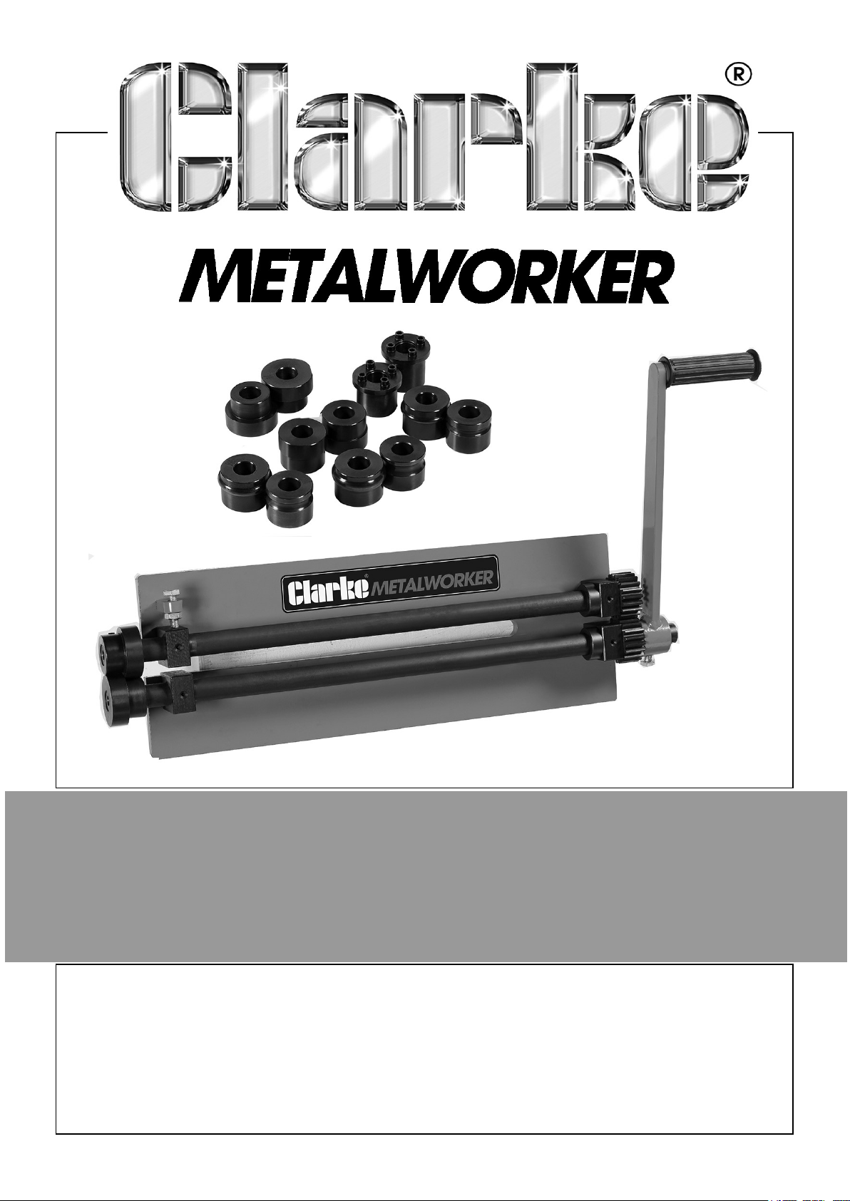
BEAD ROLLER
MODEL NO: CBRM1
PART NO: 7627907
USER INSTRUCTIONS
ORIGINAL INSTRUCTIONS GC 0724
Page 2
INTRODUCTION
Thank you for purchasing this CLARKE Bead Roller.
The bead roller is excellent for producing strengthening ribs in panels used in creating
replacement floor pans, bulkhead panels, inner wing panels etc. The gear-driven
design of the steel bead roller machine delivers maximum forming power while
requiring minimal handle force for the greatest accuracy.
The sheet metal roller comes with 6 sets of dies in total, as listed in the specification
below.
Before attempting to use the bead roller it is essential that you read this manual
thoroughly and carefully follow all instructions given. In doing so you will ensure the
safety of yourself and that of others around you and you can also look forward to the
product giving you long and satisfactory service.
SPECIFICATIONS
Capacity Bead & Flange 1.2mm (1/8”)
(mm/gauge) Shear 1.2mm (1/8”)
Bead mandrel sizes (mm//in) 6.35mm (1/4”), 9mm(3/8”), 12.7mm (1/2”)
Flange mandrels sizes 1.6mm (1/16”), 3mm (1/8”), 6.35mm (1/4”)
SAFETY PRECAUTIONS
• ALWAYS operate on a suitably strong bench with adequate light.
• ALWAYS check for signs of cracked welds or any other structural damage before
starting work. DO NOT operate if any of these conditions exist. Have repairs made
only by a CLARKE service centre.
• The components of this bead roller are designed to withstand the rated capacity. DO
NOT substitute any other components or exceed the rated capacity.
• ALWAYS ensure the workpiece is secure before applying pressure.
• DO NOT allow anyone who is unfamiliar with this tool to use the bead roller unless
they are under direct supervision.
• ALWAYS ensure the work piece is properly positioned.
• ALWAYS keep hands and fingers away from parts that may pinch or shift.
• NEVER use extension tubes to increase the length of the handle. Excessive effort
can cause damage and/or accidents.
2
Parts & Service: 020 8988 7400 / E-mail: [email protected] or [email protected]
Page 3
UNPACKING & ASSEMBLY
Ensure the product suffered no damage during transit and that all items are present.
Should any loss or damage become apparent, please contact your CLARKE dealer
immediately.
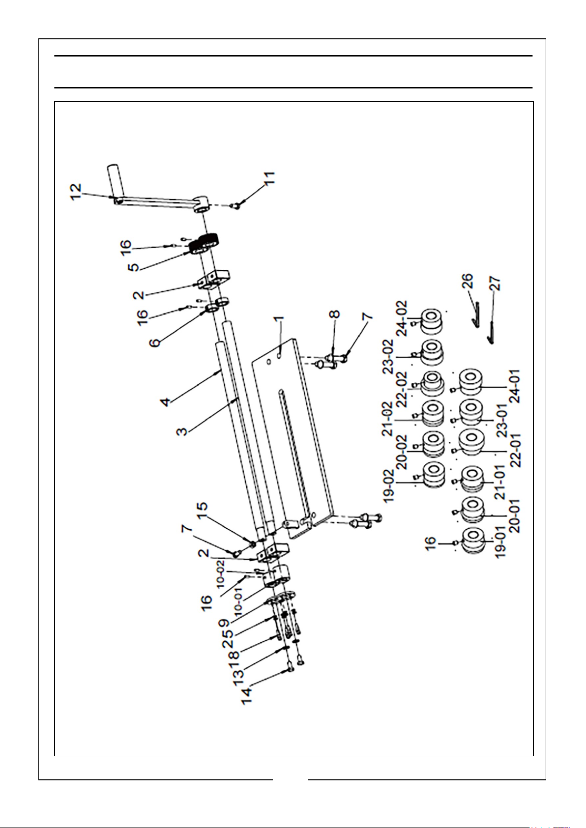
The numbers in the diagrams refer to the component parts on pages 7 & 8.
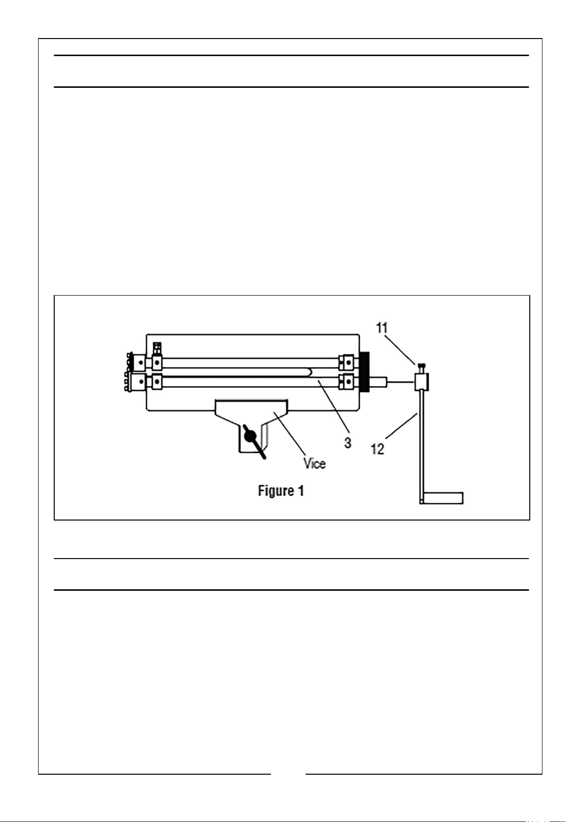
1. Place the Bead Roller in a vice as shown in Figure 1 and tighten securely to hold
the machine.
2. Slide the handle (12) onto the Driving Shaft (3).
3. Using an open ended wrench, tighten the bolt (11) securely. Ensure the bolt is
positioned over the flat surface on the Driving Shaft (3).
OPERATION
ALIGNMENT
The Bead Roller usually needs no alignment by the operator. However, poor alignment
will affect the quality of metal forming and the ability of the machine to cut sheet
metal.
If you experience either of these problems, perform the following alignment steps.
1. Set up the Bead Roller with Cutting Dies (10-01,10-02) and Cutting Plates (9) as
shown in Figure 2.
3
Parts & Service: 020 8988 7400 / E-mail: [email protected] or [email protected]
Page 4
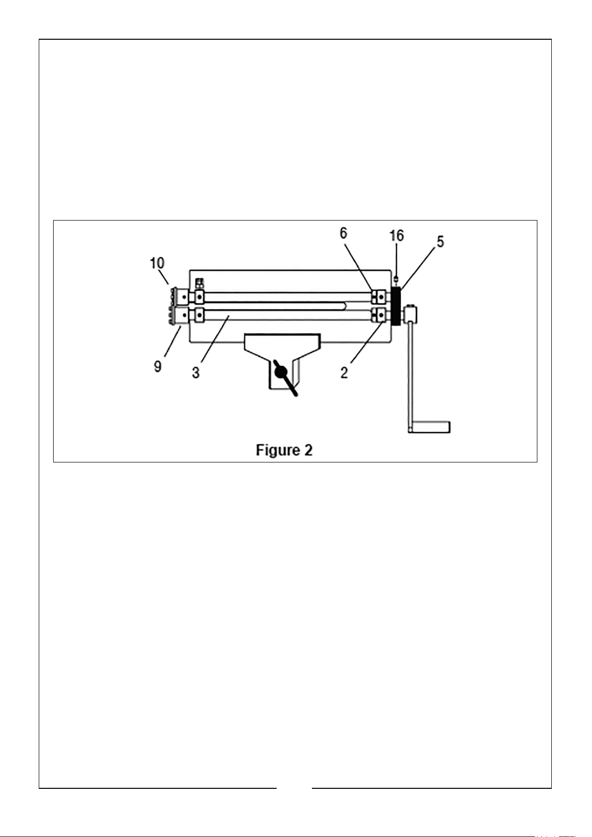
2. Inspect the Cutting Plates (9) as shown in Figure 2. When the Bead Roller is
properly aligned, the edges of the Cutting Plates (9) should be touching (or almost
touching). If they are not, perform the following steps.
NOTE: If the edges are touching and the machine does not cut material
properly, adjust the roller tension as discussed in the section titled:
Adjusting Roller Tension.
3. Using the Hex Key (27), loosen the screws (16) that secure the Gear (5) and
Collar (6) to the Driving Shaft (3).
4. Slide the Driving Shaft (3) until the edges of the Cutting Plates (9) are touching.
5. By hand, move the Collar (6) on the Driving Shaft (3), so its edge is touching the
Roller Block (2) and tighten it’s screws (16).
6. Move the gear (5) so it’s side is touching the Collar (6) on the Driving Shaft (3)
and tighten it’s screws (16).
CHANGING ROLLERS
The Bead Roller Kit comes with a variety of bead and flange dies, as well as the
cutting dies & plates that are assembled to the machine before shipping. Use the
following instructions when you change dies.
1. Using a wrench, loosen the bolt (15). See Figure 3.
2. Using a hex wrench, remove the eight screws (18) and spring washers (25),
securing the Cutting Plates (9) to the Cutting Dies (10-01,10-02). See Figure 3.
3. Remove the Cutting Plates (9).
4
Parts & Service: 020 8988 7400 / E-mail: [email protected] or [email protected]
Page 5
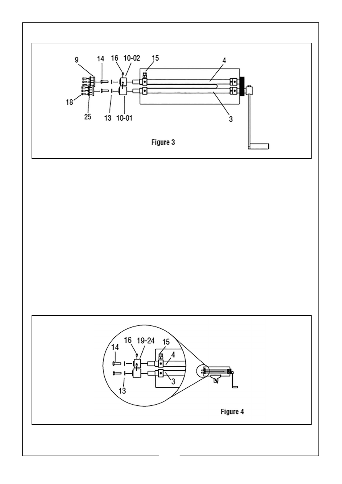
4. Using a wrench, remove the two bolts (14) securing the Cutting Dies (10-01 and
10-02) to the Driving Shaft (3) and Driving Shaft (4). Remove the washers (13).
5. Using a hex key (27), loosen the screws (16) that lock the Cutting Dies (10-01 and
10-02) onto the rollers. See Figure 3.
6. Remove the Cutting Dies (10-01 and 10-02).
INSTALLING BEAD AND FLANGE DIES
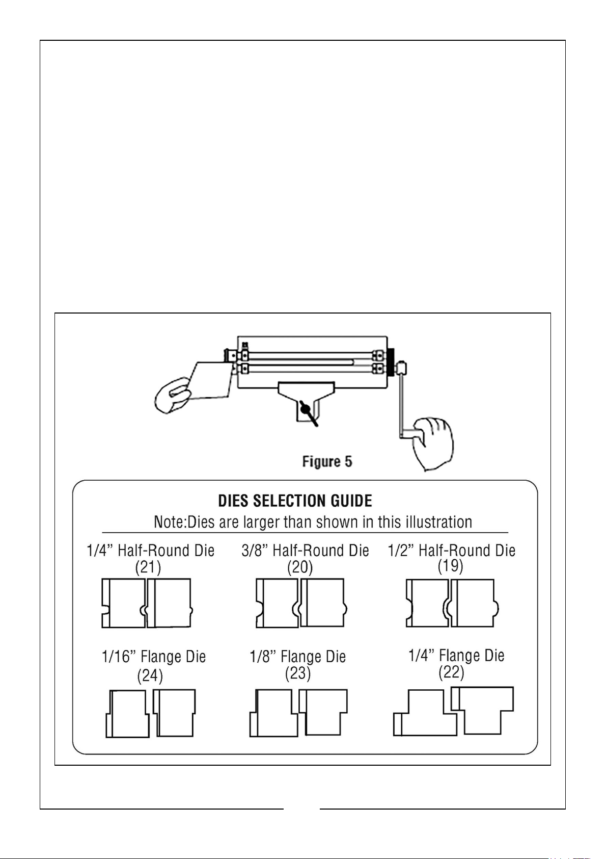
1. Select the correct bead or flange dies for the job you are going to do.
2. Slide both dies onto the Driving Shaft (3) and Driving Shaft (4) at the same time
(see Figure 4). Ensure that the screws (16) are positioned over the flat surface on
the Driving Shaft (3) and Driving Shaft (4).
3. By hand, install the two bolts (14) and washers (13). Tighten the bolts (14) with a
wrench.
4. Tighten the two screws (16).
5
Parts & Service: 020 8988 7400 / E-mail: [email protected] or [email protected]
Page 6
ADJUSTING ROLLER TENSION
1. Adjust the bolt (15) finger tight.
2. Using a wrench, tighten 1 to 3 turns, depending on desired results.
IN USE
It may be helpful if two people operate the Bead Roller depending on the size of the
workpiece. One person should guide the metal along the roller while a second person
cranks the handle.
Metal forming is an art requires good communication between the person cranking
and the one guiding the metal, particularly on corners.
1. Mark your rib, flange pattern, or cut-line on the material.
2. Insert and guide the metal through the dies while cranking the handle (see Figure
5).
6
Parts & Service: 020 8988 7400 / E-mail: [email protected] or [email protected]
Page 7
Page 8
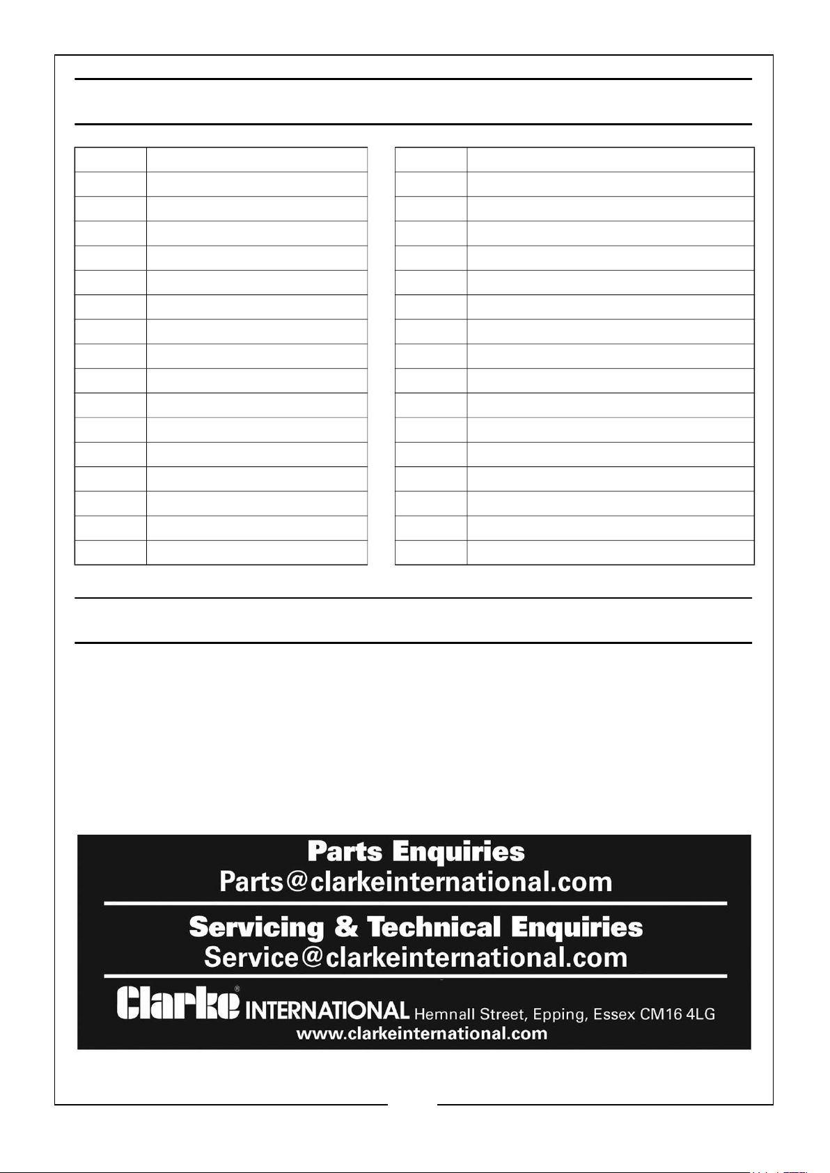
COMPONENT PARTS LIST
1 Base 17 Nut M10
2 Roller block 18 Screw M6 x 16
3 Driving shaft 19-1 1/2” Half Round Die (Convex)
4 Driving shaft 19-2 1/2” Half Round Die (Concave)
5 Gear 20-1 3/8” Half Round Die (Convex)
6 Collar 20-2 3/8” Half Round Die (Concave)
7 Bolt M14 x 30 21-1 1/4” Half Round Die (Convex)
8 Washer 14mm 21-2 1/4” Half Round Die (Concave)
9 Cutting plate 22-1 1/4” Flange Die
10-1 Long cutting die 22-2 1/4” Flange Die
10-2 Short cutting die 23-1 1/8” Flange Die
11 Bolt M10 x 20 23-2 1/8” Flange Die
12 Handle 24-1 1/16” Flange Die
13 Washer 10mm 24-2 1/16” Flange Die
14 Bolt M10 x 20 25 Spring washer 6mm
15 Bolt M10 x 35 26 Hex key 5mm
16 Screw M8 x 10 27 Hex key 4mm
GUARANTEE
This CLARKE product is guaranteed against faulty manufacture for a period of 12
months from the date of purchase. Please keep your receipt as proof of purchase.
This guarantee is invalid if the product is found to have been abused or tampered
with in any way, or not used for the purpose for which it was intended. Faulty goods
should be returned to their place of purchase, no product can be returned to us
without prior permission. This guarantee does not effect your statutory rights.
.
8
Parts & Service: 020 8988 7400 / E-mail: [email protected] or [email protected]
 Loading...