

Page 1
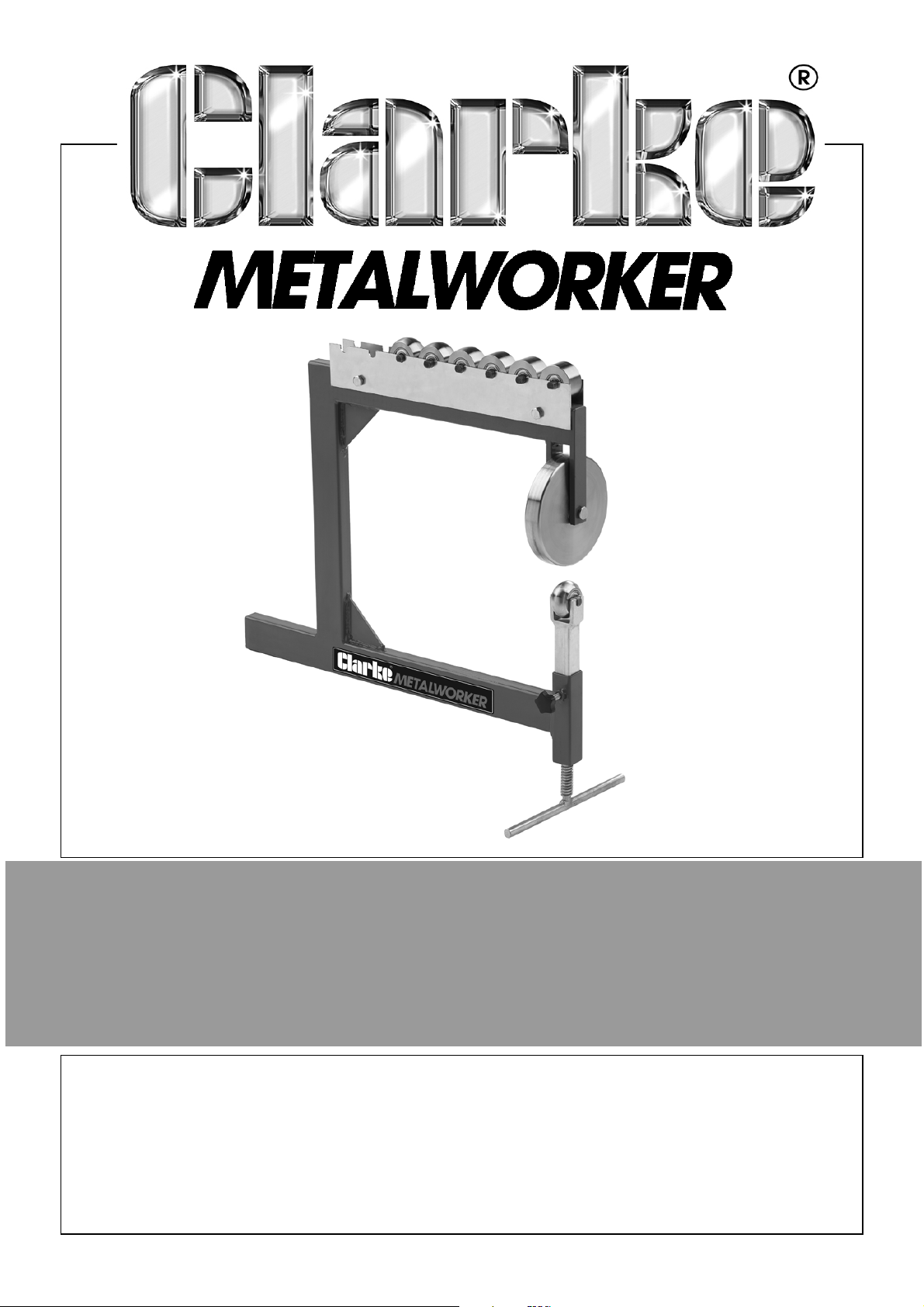
BENCH MOUNTED ENGLISH WHEEL
MODEL NO: CBMEW1
PART NO: 7627901
OPERATION
INSTRUCTIONS
ORIGINAL INSTRUCTIONS DL0321 ISS1
Page 2

INTRODUCTION
Thank you for purchasing this CLARKE English Wheel.
The CBMEW1 is suitable for forming and shaping light gauge steel and
aluminium panels and for removing dents, smoothing hammer marks,
flattening welds etc. Pressure is applied by adjusting the lower anvil roller.
Standard anvil rollers are supplied as listed in the specification.
Before attempting to use this product, please read this manual thoroughly and
follow the instructions carefully. In doing so you will ensure the safety of yourself
and that of others around you and you can look forward to your purchase
giving you long and satisfactory service.
GUARANTEE
This product is guaranteed against faulty manufacture for a period of 12
months from the date of purchase. Please keep your receipt which will be
required as proof of purchase.
This guarantee is invalid if the product is found to have been abused or
tampered with in any way, or not used for the purpose for which it was
intended.
Faulty goods should be returned to their place of purchase, no product can
be returned to us without prior permission.
This guarantee does not effect your statutory rights.
2
Page 3
SAFETY PRECAUTIONS
WARNING: THE USER MUST FOLLOW ALL INSTRUCTIONS WITHIN THIS
INSTRUCTION BOOKLET
To protect against serious injury, use common sense and observe the following
precautions when using this product. CLARKE International is not responsible
for misuse of the equipment.
•ALWAYS study these instructions before operating and pay close
attention to all warnings.
•ALWAYS keep the work area clean and well lit. Cluttered and dark
areas invite accidents.
• ALWAYS secure the English Wheel to a bench before use.
• ALWAYS keep the work area free of obstructions.
• Stay alert, watch what you are doing and use common sense when
you are using this equipment. DO NOT operate this tool when you
are tired, ill or under the influence of alcohol, drugs or medication.
• Safety equipment such as gloves and non-skid shoes/boots used for
appropriate conditions will reduce personal injuries.For best footing,
wear rubber soled footwear. Keep floor clear of oil, scrap wood etc.
• DO NOT overreach. Keep your proper footing and balance at all
times.
• Concentrate on the job in hand, no matter how trivial it may seem.
Be aware that accidents can be caused by carelessness due to
familiarity.
• DO NOT wear loose clothing or jewellery which may get caught in
moving parts. Wear protective hair covering to contain long hair.
• Keep equipment clean for the best and safest performance. Check
for misalignment or binding of moving parts, broken parts, or any
condition that may affect the tools operation. If damaged, have the
tool repaired before use.
• ALWAYS hold the workpiece securely. Large work pieces should
always be well supported to avoid loss of control.
• Sheet metal may have sharp edges. ALWAYS wear gloves when
handling sheet metal and use caution when bending and cutting.
• Rollers are heavy, take care when handling and keep hands away
from contact areas.
3
Page 4
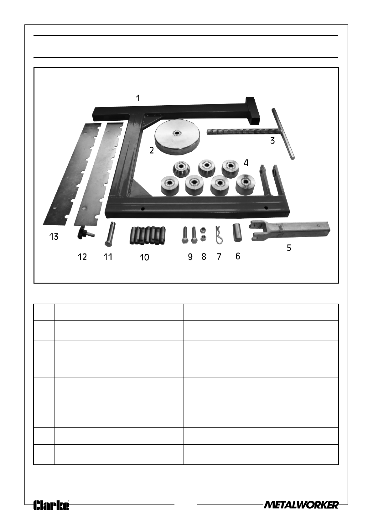
INVENTORY
NO DESCRIPTION NO DESCRIPTION
1Frame 8
2 Upper Wheel: 146mm 9
Hex Nuts
Hex Bolts
1
/4”-20
1
/4”-20 x 1 1/4”
3 Lower Wheel Adjustment Screw 10 Lower Wheel Axle Rods
4
Lower Wheels:
1
2
/2”, 5”, 9” and Flat
1
/2”,1”,1 1/2”,
11 Upper Wheel Clevis Pin
5 Lower Wheel Bracket 12 Locking Knob
6 Bracket Spacer Rod 13 Wheel Storage Rack
7
Hairpin Cotter Pin
3
/8” x 17/8”
4
Page 5
SPECIFICATION
Model CBMEW1
Dimensions
Length (mm) 700
Width (mm) 146
Height (mm) 630
Throat (mm) 400
Frame Thickness (mm) 3.2
Weight (kg) 12.15
Capacity
Mild Steel 16 Gauge, 1.5mm
Aluminium 14 Gauge, 1.8mm
Copper 14 Gauge, 1.8mm
WORKBENCH MOUNTING
• The forces exerted on the English Wheel during operation are
substantial. The English Wheel must be firmly secured in a vice (not
supplied) that is firmly secured to a workbench or table that will
support the weight and dynamic pressures of the operation.
• Make sure that you have a workbench and vice setup for the English
Wheel before performing the assembly instructions.
NOTE: Use pieces of cardboard or wood between the vice jaws and
the frame to prevent frame damage.
5
Page 6
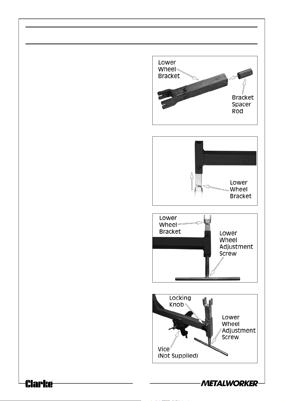
ASSEMBLY
1. Insert the bracket spacer rod into the
bottom of the lower wheel bracket,
as shown.
2. Turn the frame upside down and
insert the lower wheel bracket into
the frame, as shown.
• Inserting the wheel bracket into
the frame when it is upside down
will keep the spacer rod inside the
bracket.
3. Lay the frame down flat and thread
the lower wheel adjustment screw
into the frame opposite the wheel
bracket.
4. Secure the assembly in a bench
mounted vice (not supplied), as
described on page 5. Screw the
locking knob in the threaded hole, as
shown.
NOTE: Make sure the adjustment
screw handle has enough
clearance from the bench to
fully rotate.
6
Page 7
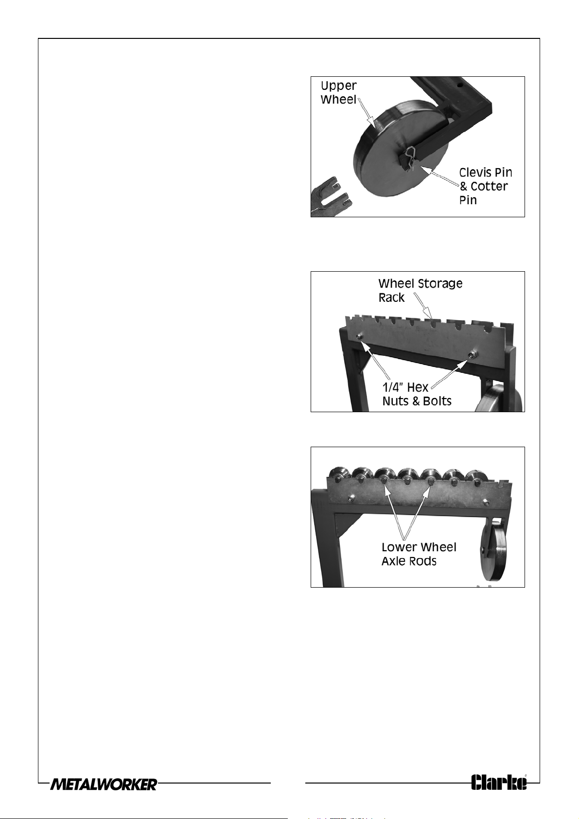
5. Position the upper wheel between
the frame arms. Insert the upper
wheel clevis pin through the arms
and wheel and secure with the
hairpin cotter pin.
NOTE: If the cotter pin does not easily
slide into the clevis pin hole,
insert it as far as you can and
use a small hammer to tap it the rest of the way.
6. Attach the lower wheel storage
1
racks to the frame top with 2 x
1
x 1
/4” hex bolts and 2 x 1/4”-20 hex
/4”-20
nuts.
7. Insert a lower wheel axle rod into
each lower wheel, then place the
assemblies on the wheel storage
rack.
7
Page 8
BEFORE STARTING WORK
WARNING: METAL EDGES CAN BE VERY SHARP. AVOID INJURIES BY
WEARING APPROVED SAFETY GLOVES.
Check that all component parts are secure and that the rollers turn freely.
Practice on some scrap metal before attempting work on the actual stock workpiece. Using an English Wheel successfully requires a considerable degree of
acquired skill and experience.
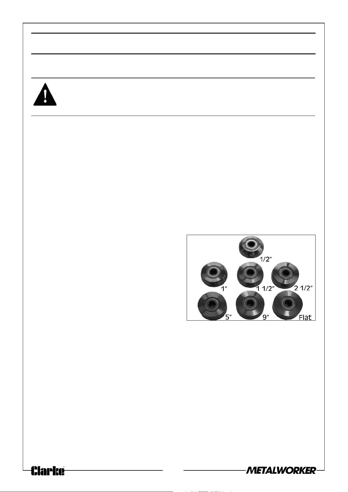
The English Wheel can be used with rollers of various radii in order to suit the task
to be carried out. These various radii allow different curves to be formed in the
workpiece.
SELECTING THE LOWER WHEEL
1. Select the appropriate lower wheel
from the storage rack and place it
on the wheel bracket. When
selecting the wheel, consider the
type and hardness of the metal
being formed as well as the desired
curvature of the metal.
• All the rollers have the same
diameter (50mm) and the same
width (25mm), but the working
surface radii are different. Note that these are always expressed in
imperial units.
• The flat wheel is used for smoothing as against forming curved
profiles.
• Smaller radius wheels produce a tighter curve on the workpiece
than the larger radius wheels. It is also common practice to change
wheels during operation in order to achieve a specific profile.
8
Page 9
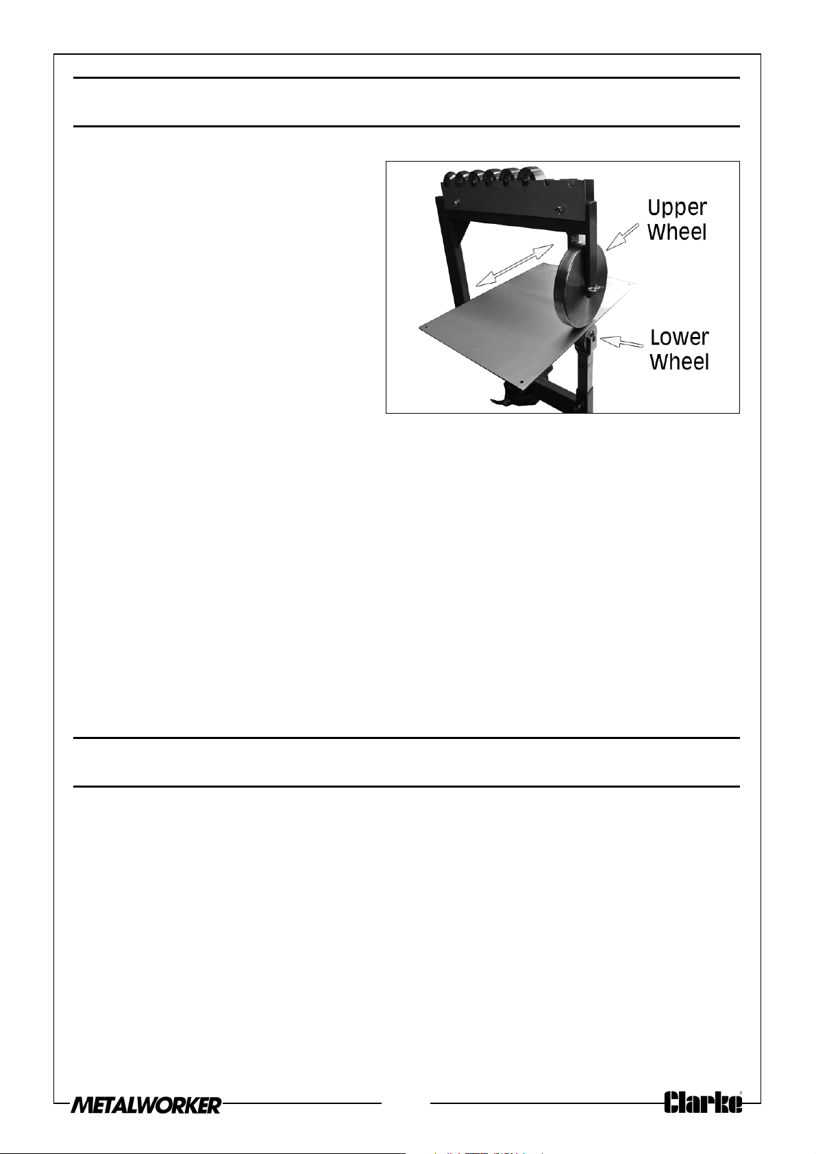
OPERATION
1. Insert the sheet metal
workpiece between the upper
and lower wheels.
2. Turn the lower wheel
adjustment screw handle to
raise the lower wheel and
gently pinch the workpiece.
• Minor adjustments to the
gap between the wheels
can be made by raising of
lowering the screw handle.
• Pinching it tightly will make it
harder to pass the metal through the wheels and may cause
unwanted creasing.
• Pinching it loosely makes work easier and therefore more accurate.
However, it may take more passes to form the required shape.
3. Before working, turn the locking knob clockwise until tight.
4. Begin forming the metal by pushing and pulling it through the wheels.
NOTE: If wheels form too high a crown in the workpiece, then use a
lower wheel with a larger flat area.
NOTE: If wheels form too low a crown in workpiece, then use a lower
wheel with a smaller flat area.
MAINTENANCE
Always inspect the wheels before use and ensure they are in top condition.
Check that all moving parts move smoothly and freely.
After use, keep the rollers clean and occasionally lubricate moving parts with
a light oil. This will also inhibit any corrosion of the metal components.
For any technical problems contact you CLARKE International Service
Department on 020-8988-7400.
9
Page 10
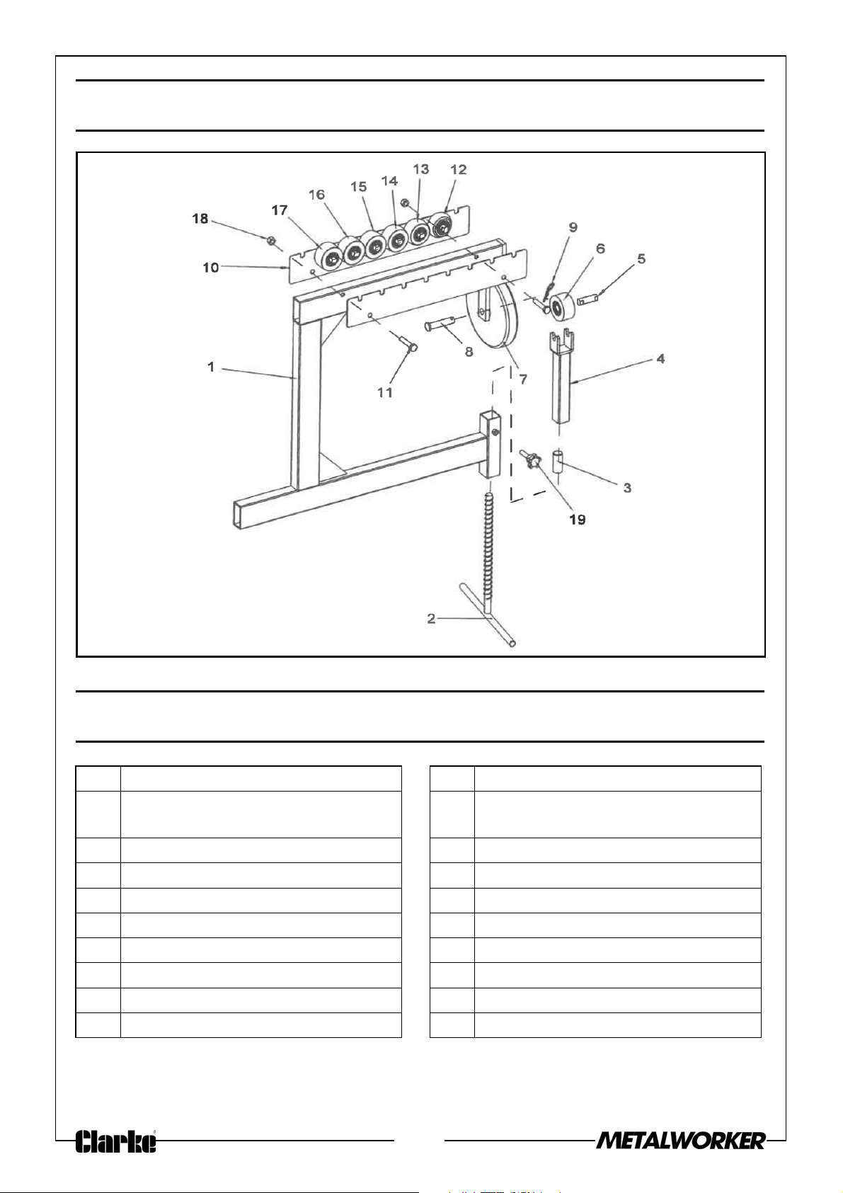
EXPLODED DIAGRAM
PARTS LIST
1 Frame 11 Hex Bolt 1/4”-20 x 1 1/4”
2 Lower Wheel Adjustment
Screw
3 Bracket Spacer Rod 13 Lower Wheel 1” Radius
4 Lower Wheel Bracket 14 Lower Wheel 1 1/2” Radius
5 Lower Wheel Axle Rod 15 Lower Wheel 2 1/2” Radius
6 Lower Wheel Flat 16 Lower Wheel 5” Radius
7 Upper Wheel 17 Lower Wheel 9” Radius
8 Upper Wheel Clevis Pin 18 Hex Nut 1/4”-20
9 Hairpin Cotter Pin 3/8” x 1 7/8” 19 Locking Knob
10 Wheel Storage Rack
12 Lower Wheel 1/2” Radius
10
Page 11
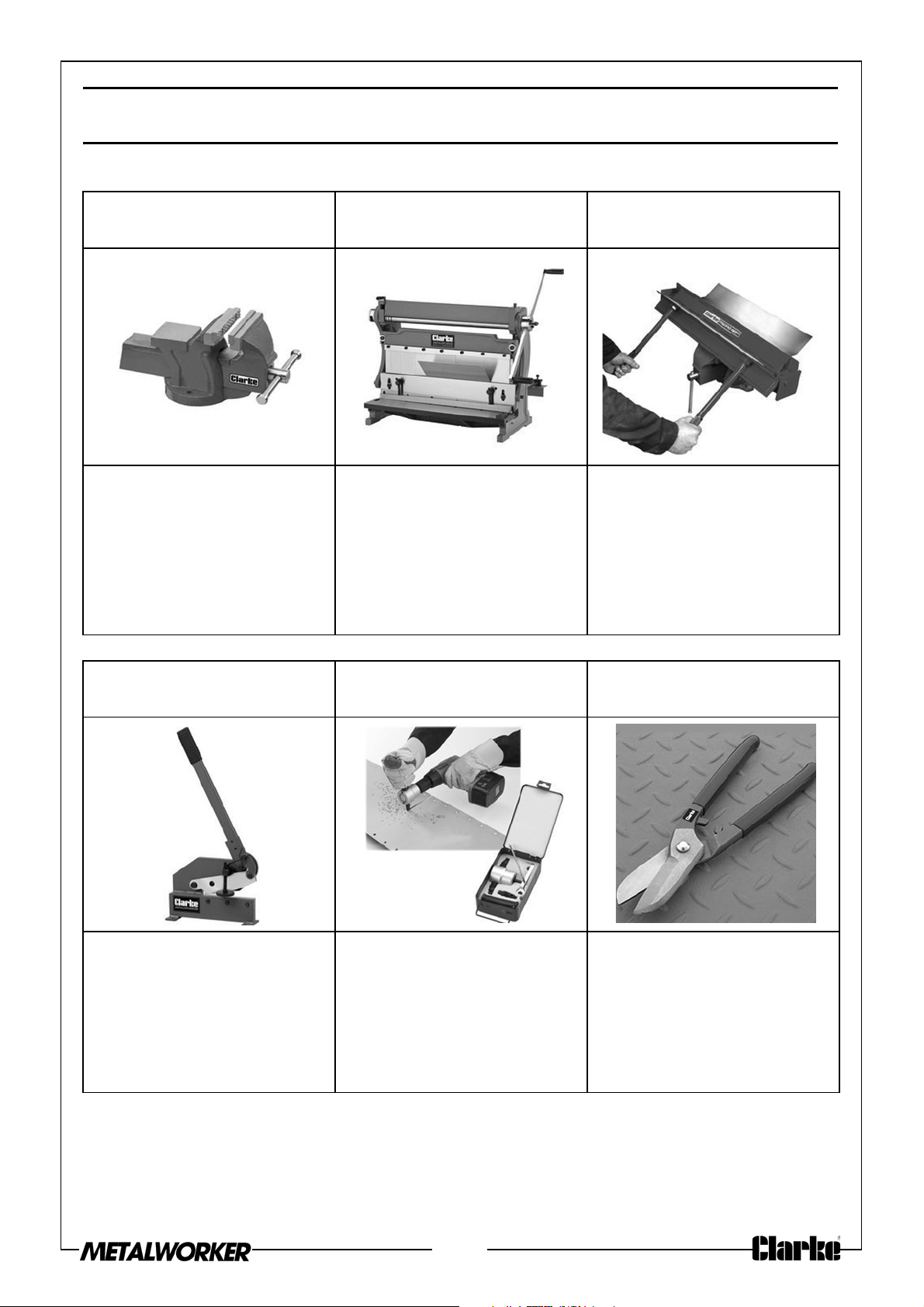
ASSOCIATED PRODUCTS
Bench Vice - CL CV3RB 3 in 1 Sheet Metal
Machine - SBR610
•75mm Jaw Width
•75mm Jaw Opening
•46mm Jaw Depth
•Part No. 6504001
•Bends, Slip Rolls &
Shears Sheet
Metal:1mm
•Minimum Rolling Dia.:
39mm
•Part No. 6560005
Sheet Metal Folder -
CMF24B
•Max Sheet Steel
Capacity:22 swg
(0.71mm)
•Max. Width Capacity:
600mm
•Part No. 7630067
150mm Sheet Metal
Shears - CPS150B
•Sheet Cutting
Capacity: 5mm
•Bar Cutting Capacity:
8mm Dia.
•Part No. 1700261
Double Headed Metal
Nibbler- DHC-2
•Max Cutting Cap.:
Steel Plate - 1.8mm,
Stainless Steel - 1.2mm,
Copper - 2mm, Plastic
- 2mm
•Part No. 6500233
10” Tin Snips - CHT308
•Max Cut: Rolled Sheet
Steel: 0.8mm
•Part No. 1801308
11
Page 12
 Loading...