

Page 1
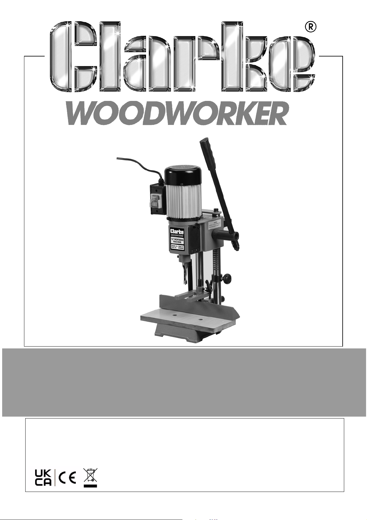
BENCH MORTISER
MODEL NO: CBM1-C
PART NO: 6500008
OPERATING & MAINTENANCE
INSTRUCTIONS
ORIGINAL INSTRUCTIONS DL0822 - ISS 1
Page 2
INTRODUCTION
Thank you for purchasing this CLARKE Bench Mortiser.
Before attempting to use this product, please read this manual thoroughly and
follow the instructions carefully. In doing so you will ensure the safety of yourself
and that of others around you, and you can look forward to your purchase
giving you long and satisfactory service.
GUARANTEE
This product is guaranteed against faulty manufacture for a period of 12
months from the date of purchase. Please keep your receipt which will be
required as proof of purchase.
This guarantee is invalid if the product is found to have been abused or
tampered with in any way, or not used for the purpose for which it was
intended.
Faulty goods should be returned to their place of purchase, no product can
be returned to us without prior permission.
This guarantee does not effect your statutory rights.
ENVIRONMENTAL RECYCLING POLICY
Through purchase of this product, the customer is taking on the
obligation to deal with the WEEE in accordance with the WEEE
regulations in relation to the treatment, recycling & recovery and
environmentally sound disposal of the WEEE.
In effect, this means that this product must not be disposed of with general
household waste. It must be disposed of according to the laws governing
Waste Electrical and Electronic Equipment (WEEE) at a recognised disposal
facility.
PARTS & SERVICE
This product has been designed to give long and trouble free service. If,
however, having followed the instructions in this booklet carefully, you
encounter problems, refer to your local CLARKE dealer.
2
Parts & Service: 020 8988 7400 / E-mail: [email protected] or [email protected]
Page 3
SPECIFICATIONS
Model Number CBM1C
Dimensions (L x W x H) 337 x 340 x 646 mm (780mm Handle Up)
Weight 27 kg
Power Supply 230V @50Hz 1ph, Class B
Rated Input Power Rating 370 Watts
Speed 1400 rpm
Spindle to Fence (Max.) 90 mm
Chisel to Table (Max.) 125 mm
Chisel Capacity 6 - 12 mm
Drill Chuck Capacity 1 - 13 mm
Chisel Shank Size 19.05 mm
Max. Workpiece Depth 125 mm
Max. mortise Depth 76 mm
Table Size 340 x 150 mm
Please note that the details and specifications contained herein are correct
at the time of going to print. However CLARKE International reserve the right to
change specifications at any time without prior notice.
SAFETY LABELS
Read instruction
manual before
use
Wear ear defenders
Wear safety
glasses
3
Parts & Service: 020 8988 7400 / E-mail: [email protected] or [email protected]
Wear a mask.
Page 4

SAFETY WARNINGS
WARNING: READ ALL SAFETY WARNINGS AND ALL INSTRUCTIONS.
FAILURE TO FOLLOW THE WARNINGS AND INSTRUCTIONS CAN RESULT IN
ELECTRIC SHOCK, FIRE AND/OR INJURY.
Save all warnings and instructions for future reference.
The term “power tool” in the warnings refers to your mains-operated electric
bench mortiser.
WORK AREA SAFETY
1. Keep work area clean and well lit. Cluttered or dark areas invite accidents.
2. DO NOT operate power tools in explosive atmospheres, such as in the
presence of flammable liquids, gases or dust. Power tools create sparks
which can ignite the dust or fumes.
3. Keep children and bystanders away while operating a power tool.
Distractions can cause you to lose control.
ELECTRICAL SAFETY
1. Power tool plugs must match the outlet. DO NOT modify the plug in any
way. DO NOT use any adapter plugs with earthed (grounded) power tools.
Unmodified plugs and matching outlets will reduce risk of electric shock.
2. AV OI D body contact with earthed or grounded surfaces, such as pipes,
radiators, ranges and refrigerators. There is an increased risk of electric
shock if your body is earthed or grounded.
3. DO NOT expose power tools to rain or wet conditions. Water entering a
power tool will increase the risk of electric shock.
4. DO NOT abuse the cable. DO NOT use the cable for carrying, pulling or
unplugging the power tool. Keep cable away from heat, oil, sharp edges
or moving parts. Damaged or entangled cables increase the risk of electric
shock.
5. When operating a power tool outdoors, use an extension cable suitable for
outdoor use. Use of a cable suitable for outdoor use reduces the risk of
electric shock.
6. If operating a power tool in a damp location is unavoidable, use a residual
current device (RCD) protected supply. Use of an RCD reduces the risk of
electric shock.
4
Parts & Service: 020 8988 7400 / E-mail: [email protected] or [email protected]
Page 5

PERSONAL SAFETY
1. Stay alert, watch what you are doing and use common sense when
operating a power tool. DO NOT use a power tool while you are tired or
under the influence of drugs, alcohol or medication. A moment of
inattention while operating power tools can result in personal injury.
2. Use personal protective equipment. ALWAYS wear eye and ear protection.
Protective equipment such as dust mask, non-skid safety shoes or hearing
protection used for appropriate conditions will reduce personal injuries. This
machine develops considerable noise when in use.
3. Prevent unintentional starting. Ensure the switch is in the OFF position before
connecting to power source.
4. Remove any adjusting key or wrench before turning the power tool on. A
wrench or a key left attached to a rotating part of the power tool can
result in personal injury.
5. DO NOT overreach. Keep proper footing and balance at all times. This
enables better control of the power tool in unexpected situations.
6. Dress correctly. DO NOT wear loose clothing or jewellery. Keep your hair,
and clothing away from moving parts. Loose clothes, jewellery or long hair
can be caught in moving parts.
POWER TOOL USE AND CARE
1. DO NOT force the power tool. Use the correct power tool for your
application. The correct power tool will do the job better and safer at the
rate for which it was designed.
2. DO NOT use the power tool if the switch does not turn it on and off. Any
power tool that cannot be controlled with the switch is dangerous and
must be repaired.
3. Disconnect the plug from the power source before making any
adjustments, changing accessories, or storing power tools. Such preventive
safety measures reduce the risk of starting the power tool accidentally.
4. Store idle power tools out of the reach of children and DO NOT let persons
unfamiliar with the power tool or these instructions to operate the power
tool. Power tools are dangerous in the hands of untrained users.
5. Maintain power tools. Check for misalignment or binding of moving parts,
breakage of parts and any other condition that can affect the power
tool's operation. If damaged, have the power tool repaired before use.
Many accidents are caused by poorly maintained power tools.
6. Keep cutting tools sharp and clean. Sharp cutting edges are less likely to
bind and are easier to control.
5
Parts & Service: 020 8988 7400 / E-mail: [email protected] or [email protected]
Page 6

7. Use the power tool, accessories and tool bits etc. in accordance with these
instructions, taking into account the working conditions and the work to be
performed. Use of the power tool for operations different from those
intended could result in a hazardous situation.
ADDITIONAL SAFETY INSTRUCTIONS FOR MORTICING MACHINES
1. DO NOT use until unit is completely assembled and installed according to
these instructions.
2. If you are not thoroughly familiar with the operation of morticing machines,
obtain advice from a qualified person.
3. Ensure the machine is secured to a workbench to prevent it from tipping
over during operation, see page 10.
4. NEVER turn the morticing machine on before clearing the table of all
objects (tools, scrap pieces, etc.).
5. ALWAYS keep hands, fingers and hair well away from the rotating bit.
6. DO NOT attempt to mortise materials that DO NOT have a flat surface,
unless a suitable support is used.
7. ALWAYS use the ‘Hold Down’ to prevent work from lifting when withdrawing
the chisel.
8. ALWAYS support the workpiece securely against fence to prevent rotation.
9. ALWAYS ensure chisel and bit is sharp, undamaged and properly secured.
10. ALWAYS ensure the chuck key is removed before starting.
11. NEVER start the machine with the drill bit or chisel pressed against the
workpiece.
12. NEVER perform layout, assembly, or set-up work on the machine with the
cutting tool rotating.
13. ALWAYS adjust the depth stop to avoid drilling into the table.
14. ALWAYS stop the machine before removing scrap pieces from the table.
15. ALWAYS shut off the power, remove the drill bit and chisel and clean the
table before leaving the machine.
16. NEVER place your fingers in a position where the drill or cutting tool could
contact them if the workpiece should shift unexpectedly.
6
Parts & Service: 020 8988 7400 / E-mail: [email protected] or [email protected]
Page 7
ELECTRICAL CONNECTIONS
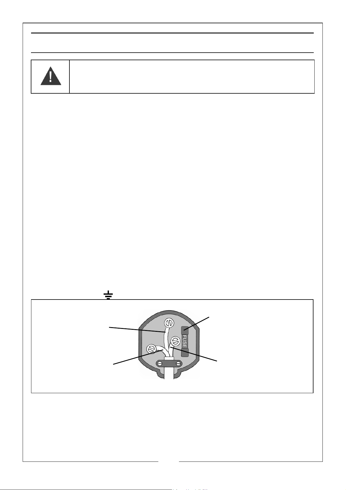
Plug must be BS1363/A approved.
Always fit a 5 Amp fuse.
Ensure that the outer sheath of the cable is firmly held by the clamp
Neutral
(Blue)
Live
(Brown)
Earth
(Green and Yellow)
WARNING! READ THESE ELECTRICAL SAFETY INSTRUCTIONS
THOROUGHLY BEFORE CONNECTING THE PRODUCT TO THE
MAINS SUPPLY.
Before switching the product on, make sure that the voltage of your electricity
supply is the same as that indicated on the rating plate. This product is
designed to operate on 230VAC 50Hz. Connecting it to any other power
source may cause damage.
This product may be fitted with a non-rewireable plug. If it is necessary to
change the fuse in the plug, the fuse cover must be refitted. If the fuse cover
becomes lost or damaged, the plug must not be used until a suitable
replacement is obtained.
If the plug has to be changed because it is not suitable for your socket, or due
to damage, it should be cut off and a replacement fitted, following the wiring
instructions shown below. The old plug must be disposed of safely, as insertion
into a mains socket could cause an electrical hazard.
If the colours of the wires in the power cable of this product do not correspond
with the markings on the terminals of your plug, proceed as follows.
•The Blue wire must be connected to the terminal marked N or
coloured Black.
•The Brown wire must be connected to the terminal marked L or
coloured Red.
•The Yellow and Green wire must be connected to the terminal
marked E or or coloured Green.
We strongly recommend that this machine is connected to the mains supply
via a Residual Current Device (RCD). If in any doubt, consult a qualified
electrician. DO NOT attempt any repairs yourself.
Parts & Service: 020 8988 7400 / E-mail: [email protected] or [email protected]
7
Page 8
Page 9
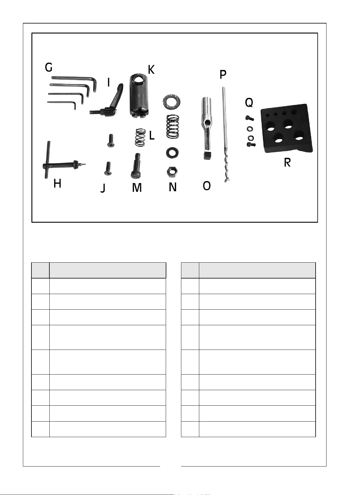
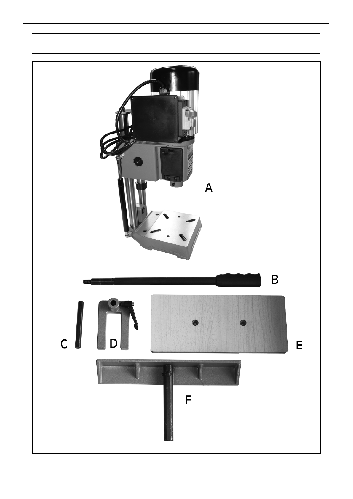
When unpacking please check contents and advise your dealer immediately
if any parts are missing. The essential components are as follows.
NO DESCRIPTION NO DESCRIPTION
A Motor, Head & Stand Unit
B Raise/Lower Handle
CHold Down Bar
DHold Down Clamp & Lock
Handle
ETable
FFence
G 4 x Hex Keys
H Chuck Key
I Fence Lock Handle
J 2 x Counter Sunk Bolts for Table
KHandle Lever Assembly
LHandle Lever Spring
MHandle Lever Bolt
NHandle Nut, Spring &
2 x Washers
OChisel
P Drill Bit
Q 2 x Tool Holder Bolt & Washer
R Tool & Chisel Holder
9
Parts & Service: 020 8988 7400 / E-mail: [email protected] or [email protected]
Page 10
ASSEMBLY
WARNING: FOR YOUR OWN SAFETY, DO NOT CONNECT THE MORTICING
MACHINE TO A POWER SOURCE UNTIL IT IS FULLY ASSEMBLED, AND YOU
HAVE READ AND UNDERSTOOD ALL SAFETY AND OPERATIONAL
INSTRUCTIONS.
INSTALLATION
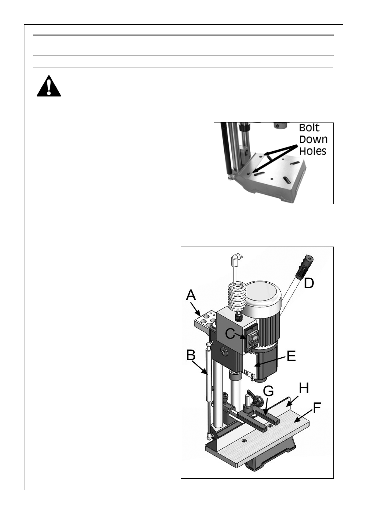
IMPORTANT: Before using the machine, it
must be bolted down to a firm and stable
workbench to prevent it from tipping during
operation. Two holes are supplied in the base
for this purpose.
Additionally, the chisel and bit must be
installed and various adjustments made
before the machine can be used. These procedures are described on the fol-
lowing pages.
KNOW YOUR MORTISER
A: Tool Storage Rack
B: Gas Spring
C: On/Off Switch
D: Handle Lever
E: Chuck Access Cover
F: Table
G: Hold Down
H: Fence
10
Parts & Service: 020 8988 7400 / E-mail: [email protected] or [email protected]
Page 11
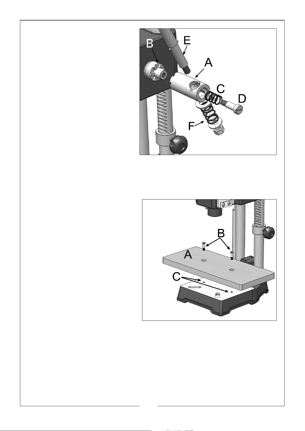
INSTALLING THE HANDLE LEVER.
1. Place the hub of the handle
lever assembly (A) to the end
of the pinion shaft (B) and
fasten handle to pinion shaft
using special screw (D) and
spring (C).
2. Fasten the handle (E) using
the nut, washers and spring
(F) into the hub of the handle
(A).
3. Raise the mortising machine
head to the up position by
turning the handle (E)
clockwise.
NOTE: Handle (E) is spring loaded and can be repositioned by pulling out
the handle to the right and repositioning it on the pinion shaft (B).
INSTALLING THE TABLE
1. Screw the table (A) to the
base using the two flat head
screws (B).
2. Thread the two screws (B) into
the two holes (C) in the table
base.
3. The table (A) can be moved in
or out by loosening the two
screws (B) and repositioning
the table, and then tightening
the screws (B).
11
Parts & Service: 020 8988 7400 / E-mail: [email protected] or [email protected]
Page 12
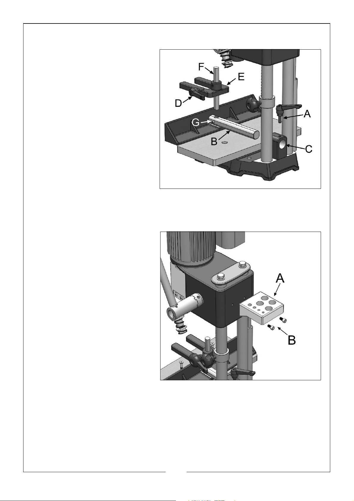
INSTALLING THE FENCE AND HOLD DOWN
1. Insert the fence bar (B) into
the hole (C) and fasten by
the lock handle (A).
2. Insert the hold down (E) onto
the hold down bar (F) and
fasten with the lock handle
(D).
3. Place the hold down bar (F)
into the fence bar (B)mortise
and fasten using the screw
(G).
INSTALLING THE TOOL AND CHISEL HOLDER
1. Place the tool and chisel
holder (A) to the rear of the
machine and screw into
place using the two bolts (B)
as shown.
NOTE: The holder will hold the
chuck key, wrench,
chisels and bits when
not in use.
12
Parts & Service: 020 8988 7400 / E-mail: [email protected] or [email protected]
Page 13
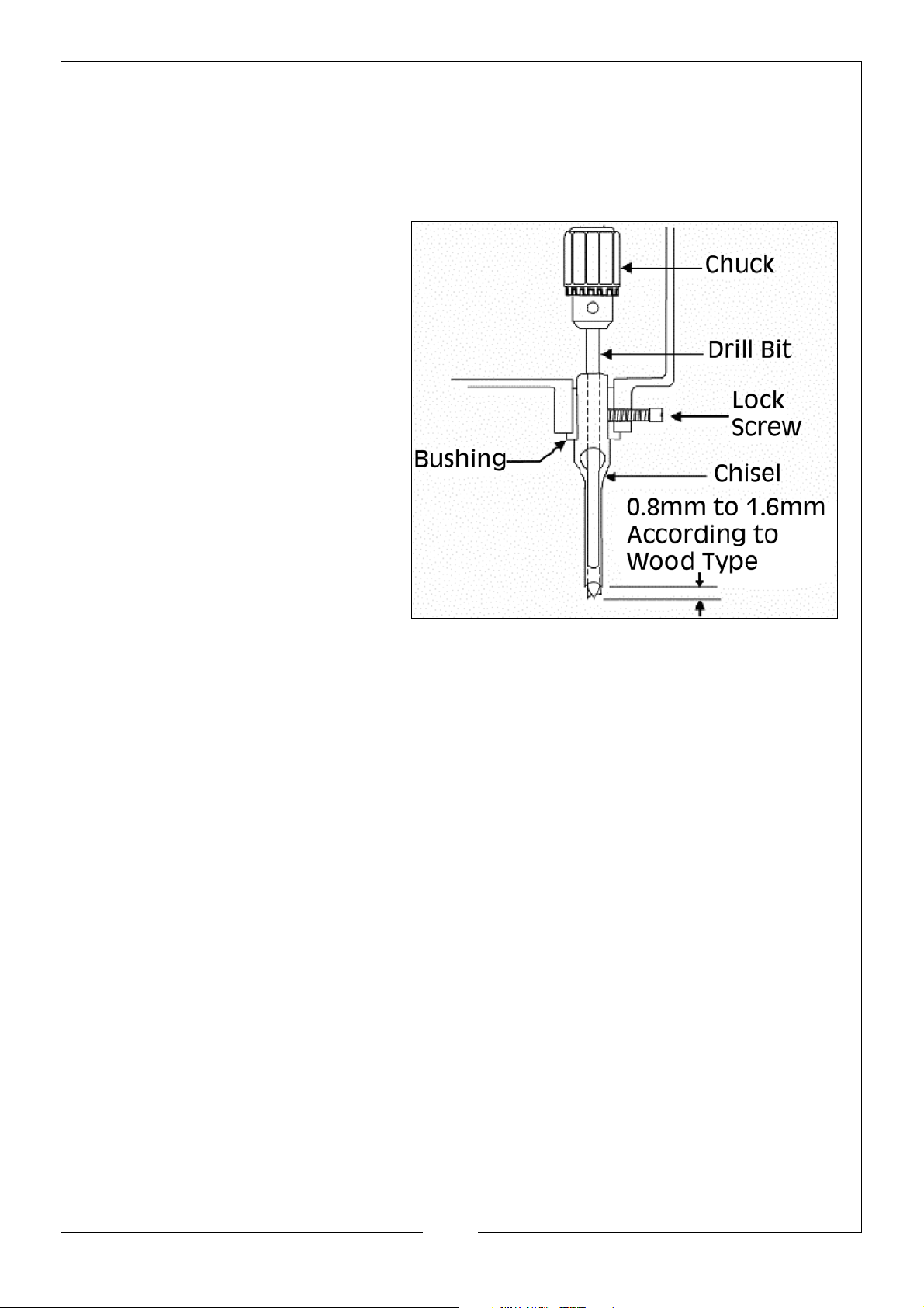
INSTALLING THE CHISEL AND BIT
CAUTION: THE CHISEL AND DRILL BIT ARE EXTREMELY SHARP...TAKE CARE WHEN
HANDLING!
Installing the Chisel
1. Loosen the lock screw.
2. Insert the chisel bushing (with
the hole facing the screw
hole in the head) into the
head. Tighten the screw just
enough to hold the chisel in
place.
NOTE: Set the slot in the side of
the chisel to the left or
right, NOT to the front
or back. This will allow
chips to escape when
cutting.
3. Push the chisel up as far as
possible into the head. Then
lower the chisel
approximately 0.8mm to 1.6mm, depending on the type of wood being
worked. Tighten the screw to hold the chisel in place.
Installing the Bit
1. Open the chuck access cover at either side of the head, by unscrewing
the single securing screw then pulling down on the plastic catch to expose
the chuck.
2. Push the bit up through the chisel opening as far as it will go. Lock the drill
bit in place with the chuck key.
3. Loosen screw and push chisel up against the bushing, then tighten screw.
This should provide the proper distance between the points of the chisel
and the bit.
13
Parts & Service: 020 8988 7400 / E-mail: [email protected] or [email protected]
Page 14
PREPARING FOR USE
WARNING: MAKE SURE THE MACHINE IS DISCONNECTED FROM THE
MAINS SUPPLY BEFORE PERFORMING CHECKS, ADJUSTMENTS, OR SETUP
PROCEDURES.
Note is important that the drill bit bottoms out on the CHISEL and NOT the
chuck, before setting the 1/16” (2mm) clearance.
I f the bit does bottom out in the chuck first, slacken off the grub screw securing
the chisel and lower it approx. 1/16” (2mm) and try again.
• Alternatively, grind off a portion of the drill shank.
This adjustment is IMPORTANT to ensure a proper clearance is provided
between the cutting tips of the bit and the points of the chisel.
For certain types of wood, it may be necessary to increase this distance up to
a maximum of 3/16” (5mm). This will become obvious when cutting
commences and chips are not being ejected satisfactorily.
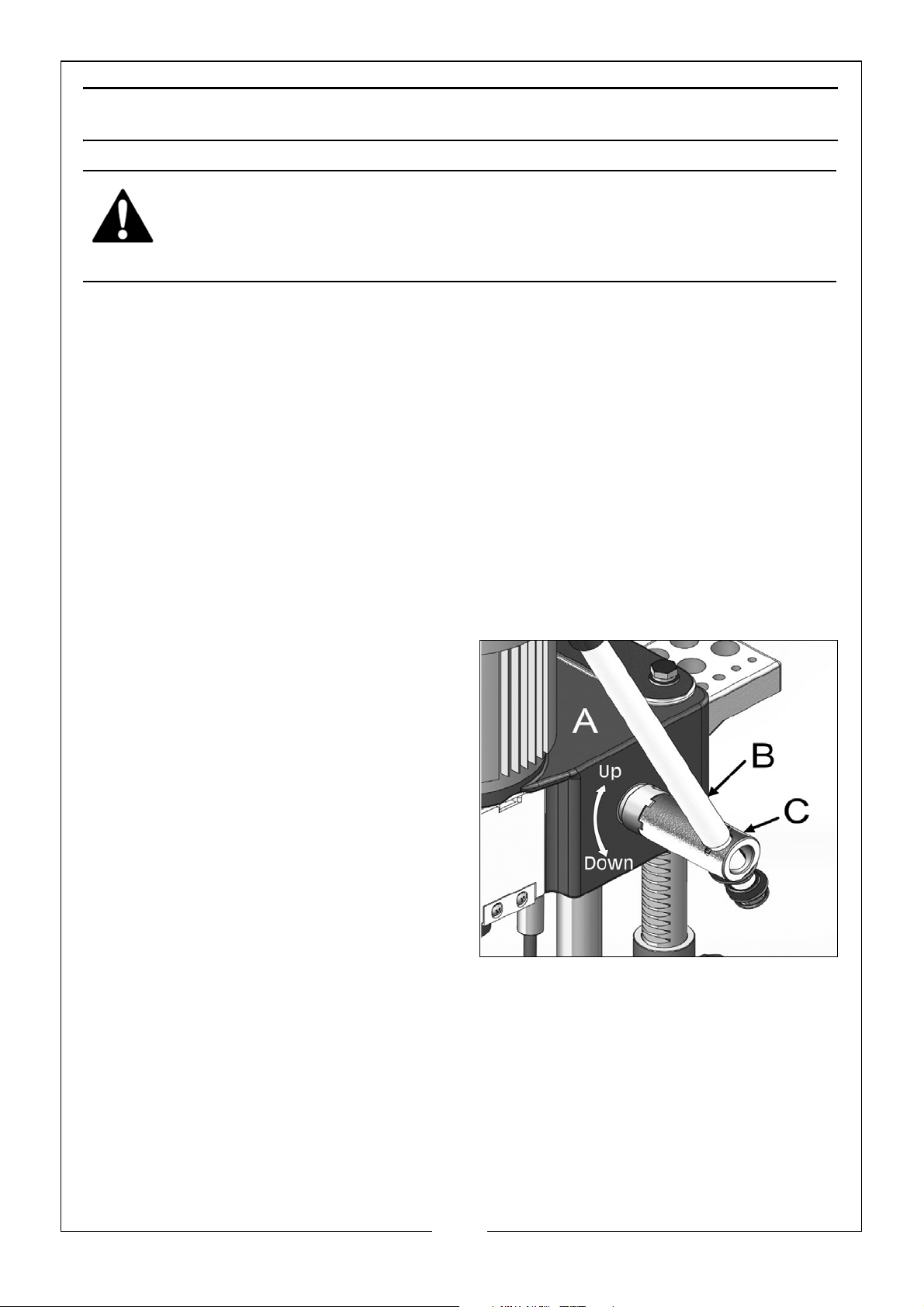
RAISING & LOWERING THE HEAD
The head (A) is raised and lowered by
means of the lever (B). For maximum
leverage during morticing, the lever (B)
can be repositioned by pulling out the
hub (C) of the lever assembly and
repositioning the hub on the pinion
shaft.
14
Parts & Service: 020 8988 7400 / E-mail: [email protected] or [email protected]
Page 15
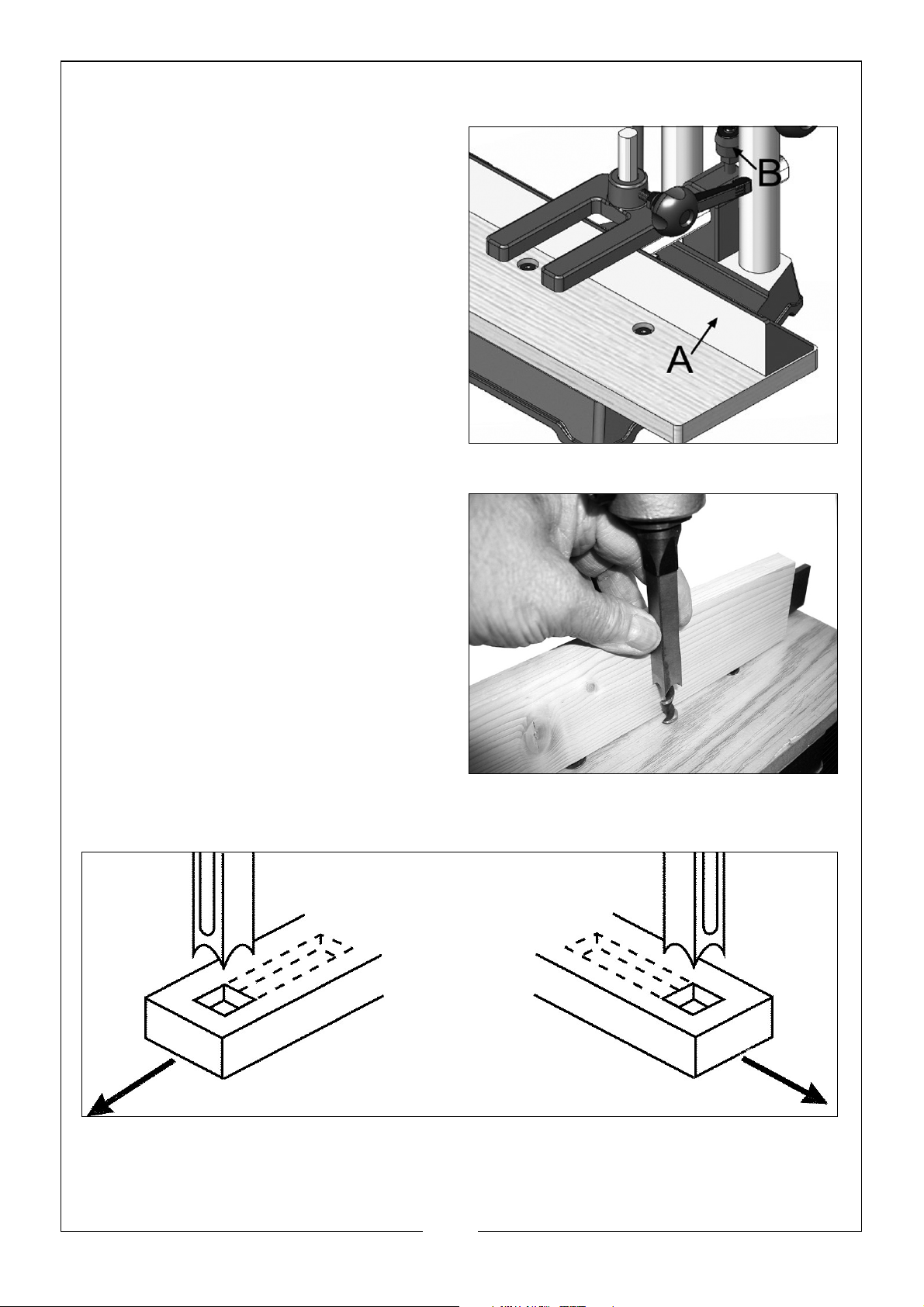
ADJUSTING THE FENCE
4. The fence (A) can be moved in or
out by slackening the locking lever
(B), sliding the fence to the desired
position and re-tightening the
locking lever.
NOTE: The lever (B) is spring loaded
and can be repositioned by
pulling up on the lever and
repositioning it on the
serrated nut located
underneath the lever.
ADJUSTING CHISEL PARALLEL TO WORKPIECE
It is important that the chisel is square
to the workpiece. To achieve this,
slacken the chisel securing screw and
rotating the chisel until the back
surface is flat against the workpiece,
or a piece of wood with parallel sides,
resting against the fence, then
retighten the screw, ensuring a
distance of at least 1/16” (2mm) is
maintained between the chisel and
the end of the drill bit.
It is also IMPORTANT to remember that
the slot in the side of the chisel should always face TOWARDS THE DIRECTION
OF MOVEMENT OF THE WORKPIECE (see diagram below).
15
Parts & Service: 020 8988 7400 / E-mail: [email protected] or [email protected]
Page 16
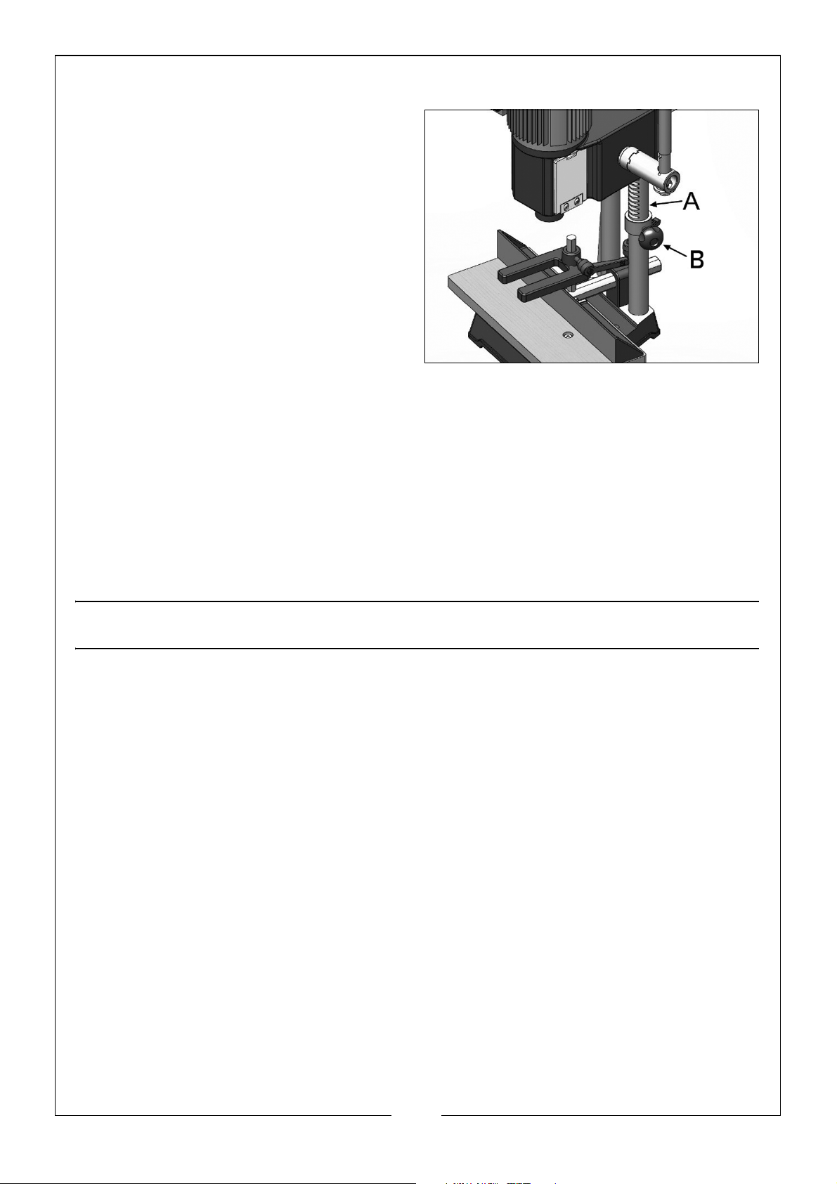
ADJUSTING THE DEPTH STOP
A depth stop is provided which can
be used to limit the depth of the chisel
cut.
To adjust the depth stop guide (A),
loosen the securing knob (B) so that
the stop is capable of being moved,
but will not drop under its own weight,
then raise the stop so that it contacts
the underside of the head.
Lower the head to the desired depth,
then tighten the securing knob (B).
ADJUSTING THE HOLD DOWN
The purpose of the ‘Hold Down’ in to prevent the workpiece from lifting as the
chisel is raised up, out of the hole.
The hold down should be adjusted so it just touches the top of the workpiece
and allows the workpiece to slide left or right. Packing pieces may be used if
necessary.
OPERATION
1. Set the fence to suit the position of the mortise on the workpiece. Make
sure the fence and chisel are square to each other (see p15), and tighten
in place.
2. Make any fine adjustments to the fence to move the workpiece in or out
by using the adjuster at the rear of the fence (see p15).
3. Set the Depth Stop to the required depth of cut as described above.
4. Ensure the Hold Down rests gently on the surface of the workpiece, but not
so tight as it prevents the workpiece from moving, and lock into position as
described above. If necessary, use packing pieces between the
workpiece and the hold down.
• If working on long workpieces, support the timber along its length.
5. Ensure the workpiece is held firmly against the fence.
16
Parts & Service: 020 8988 7400 / E-mail: [email protected] or [email protected]
Page 17

SWITCHING ON AND OFF
1. The ON-OFF switch is located on
the left hand side of the motor.
Push the GREEN (I) button to switch
the machine ON.
2. Push the RED (O) button to switch
the machine OFF.
NOTE: The switch is a No Volt
Release type. If the supply is
interrupted, the ON/OFF
switch will automatically
revert to the OFF position. This is a safety device to prevent the
machine from starting again, should the supply be restored.
3. With the machine running, feed the chisel and bit steadily into the
workpiece by pulling down on the operating handle.
NOTES
• It is recommended that you check the position and depth of cut, on
a piece of scrap before cutting your workpiece.
• The rate of penetration of the chisel must be fast enough to prevent
burning at the tip of the drill bit, but not so fast as to cause the
machine to slow or stall. With experience you will find suitable feed
rates to suit various types of timber.
• You may encounter smoke from the bit or material once the chisel
has engaged the material. The smoke created is a natural operating
occurrence in hollow chisel morticing and is caused by material
chip friction and the resins in the stock being burned off. Blueing of
the chisel after initial use is not indicative of a dull chisel, but a
combination of friction and resin buildup on the cutting faces of the
chisel.
• A dull chisel can be detected by the amount of excess force
required to complete a cut.
• After the first cut, the workpiece must be moved along in the correct
direction relative to the slot in the chisel, to allow chips to clear
freely. Move the workpiece so that the chisel slot is releasing chips
into the already cut part of the mortise.
• DO NOT have the slot against the blind end of the mortise, as the
chips will not be able to clear from the chisel. This will cause
overheating and possible breakage to the chisel or bit.
• When cutting deep mortises, make the cut in several stages of
approximately 25mm each, to allow chips to clear.
17
Parts & Service: 020 8988 7400 / E-mail: [email protected] or [email protected]
Page 18
• When performing a through mortise, a piece of wood should be
placed between the workpiece and the table. This prevents the
wood from splintering when breaking through the bottom of the
mortise and also prevents damage to the table.
• ALWAYS switch the morticing machine off after use. NEVER leave the
machine running unattended.
MAINTENANCE
WARNING: FOR YOUR OWN SAFETY, TURN OFF POWER AND DISCONNECT
TOOL FROM POWER SOURCE BEFORE PERFORMING ANY MAINTENANCE.
The machine is maintenance free except for periodically cleaning away any
dust accumulation and the application a light coat of oil to all non- painted
surfaces, particularly the two columns.
All of the bearings are packed with grease at the factory and require no
further lubrication.
SHARPENING THE DRILL BIT & CHISEL
For best performance the chisel and bit need to be kept sharp. Blunt cutting
edges will give untidy and inaccurate mortises, and can cause overheating
and breaking of the chisel and bit.Chisels and bits will need replacing when
they become badly worn and difficult to sharpen.
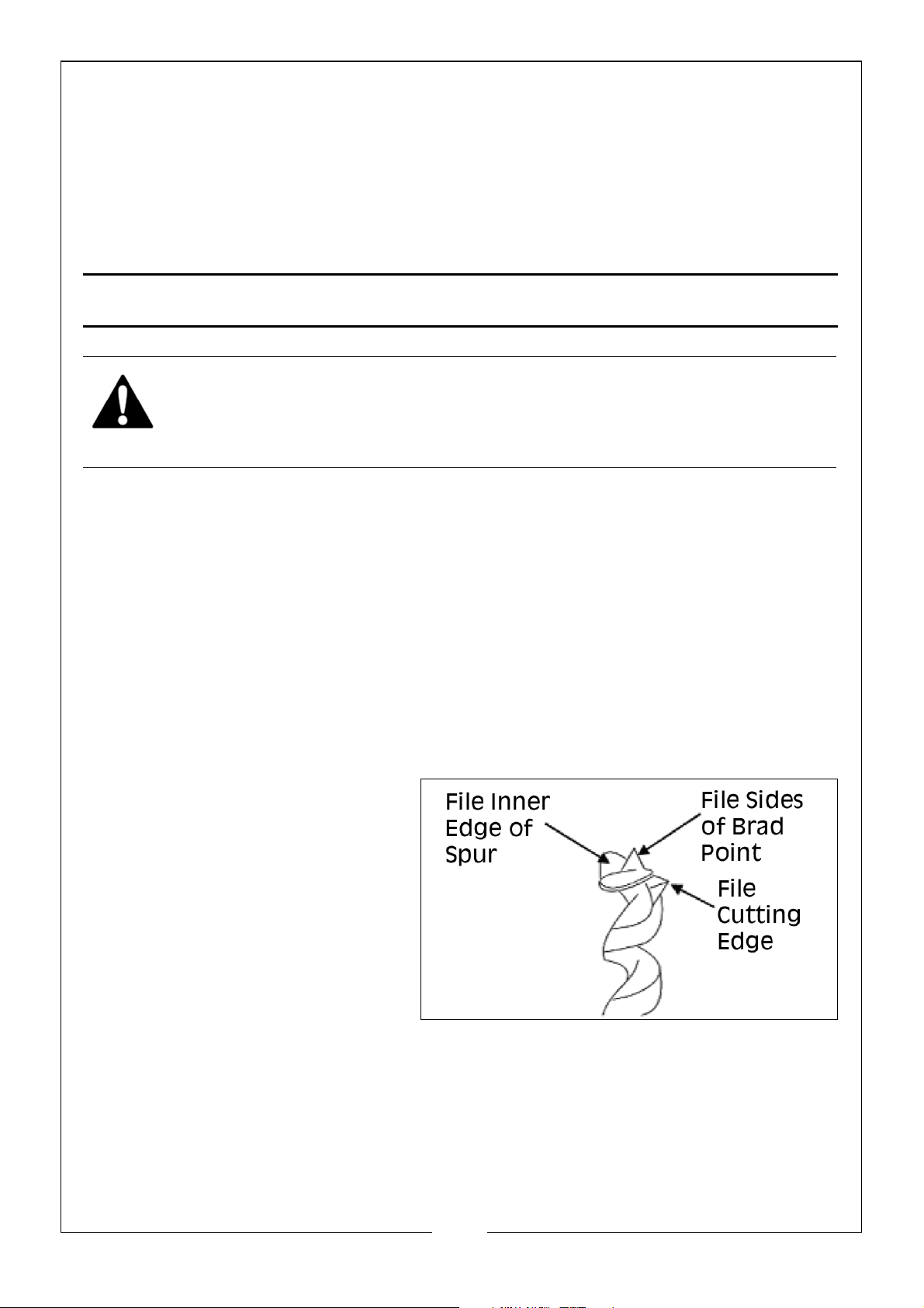
1. Sharpen the bit by using a
small smooth file, following
the original shape of the bit.
File the inside edge of the
spur, the sides of the brad
point, and the cutting edge
inwards towards the flutes of
the bit to restore sharpness.
DO NOT file the outside edge
of the spur as this will affect
the diameter of the bit.
18
Parts & Service: 020 8988 7400 / E-mail: [email protected] or [email protected]
Page 19
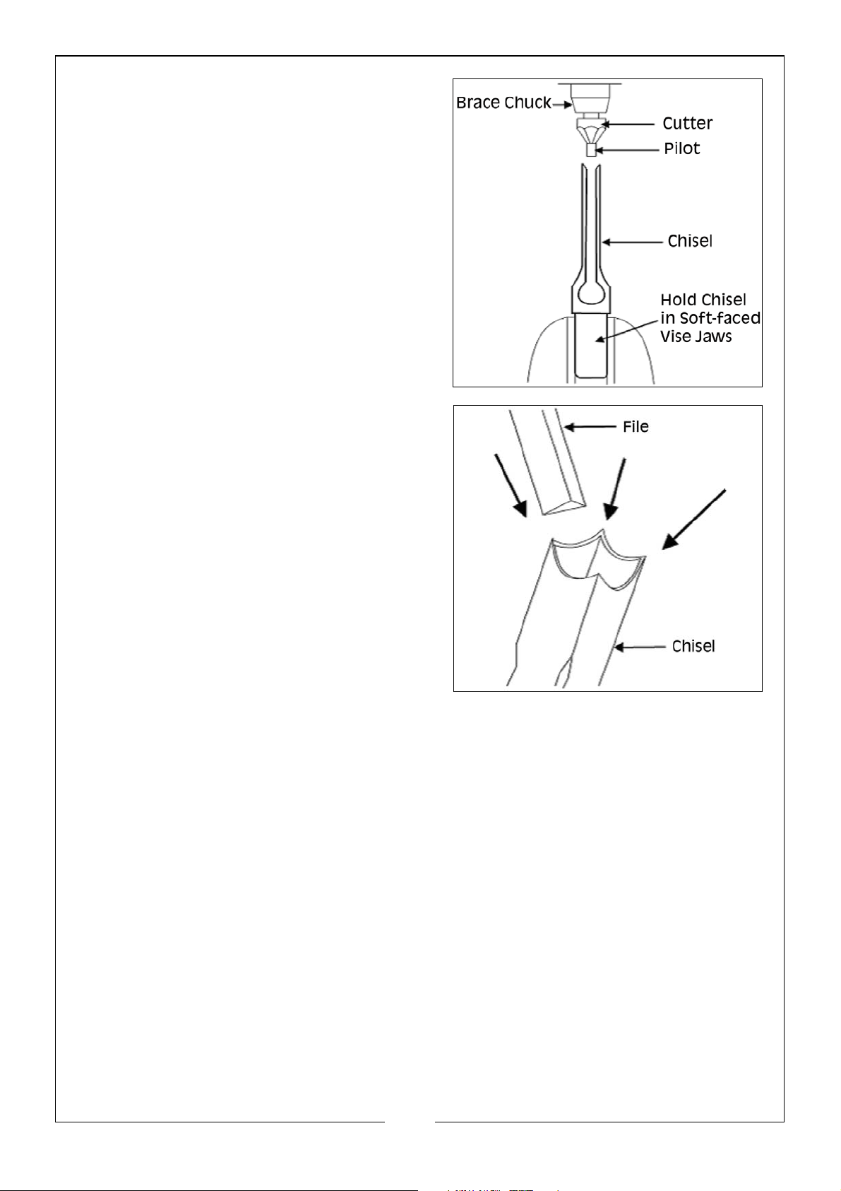
2. Use a mortise chisel cutter with the
correct size pilot to sharpen the chisel
(pilot size will differ depending on the
size of the chisel). Two or three turns of
the cutter in a carpenters hand brace
should be enough to sharpen the
chisel.
3. Use a small, triangular, smooth file to
relieve the inner corners of the chisel.
Remove any burrs from the outside of
the chisel with a fine oil-stone.
The following replacement mortise chisels can be obtained from your local
Clarke dealership
• 1/4” Mortise Chisel, Part Number: 6500025
• 3/8” Mortise Chisel, Part Number: 6500026
• 1/2” Mortise Chisel, Part Number: 6500027
• 5/8” Mortise Chisel, Part Number: 6500028
19
Parts & Service: 020 8988 7400 / E-mail: [email protected] or [email protected]
Page 20
Page 21

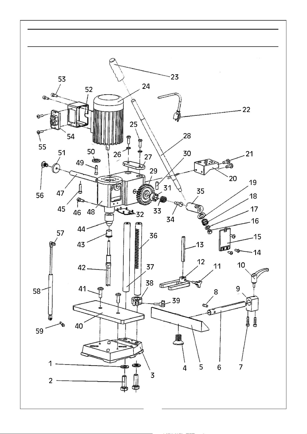
COMPONENT PARTS
No Description No Description
1 Lock Washer 31 Connecting Bend A
2 Bolt 32 Cover
3 Base 33 Spring
4Screw 34Screw
5 Fence 35 Connecting Bend B
6Guide Column 36Gear Column
7 Screw 37 Guide Column
8 Screw 38 Depth Set Guide
9 Guide Bracket 39 Lock Handle
10 Lock Handle 40 Wood Table
11 Knob 41 Screw
12 Hold-Down Clamp 42 Chisel
13 Guide Column 43 Chisel Bushing
14 Screw 44 Chuck
15 Cover 45 Screw
16 Nut 46 Screw
17 Washer 47 Gear Shaft
18 Spring 48 Gear Casing
19 Washer 49 Screw
20 Tool Rack 50 Lock Washer
21 Screw 51 Cover
22 Power Cable 52 Switch Box
23 Handle Grip 53 Screw
24 Motor 54 On/Off Switch
25 Bolt 55 Screw
26 Lock Washer 56 Screw
27 Step Plate 57 Screw
28 Handle 58 Gas Spring
29 Gear 59 Screw
30 Pin
21
Parts & Service: 020 8988 7400 / E-mail: [email protected] or [email protected]
Page 22

DECLARATION OF CONFORMITY - UKCA
22
Parts & Service: 020 8988 7400 / E-mail: [email protected] or [email protected]
Page 23

DECLARATION OF CONFORMITY - CE
23
Parts & Service: 020 8988 7400 / E-mail: [email protected] or [email protected]
Page 24

 Loading...