

Page 1
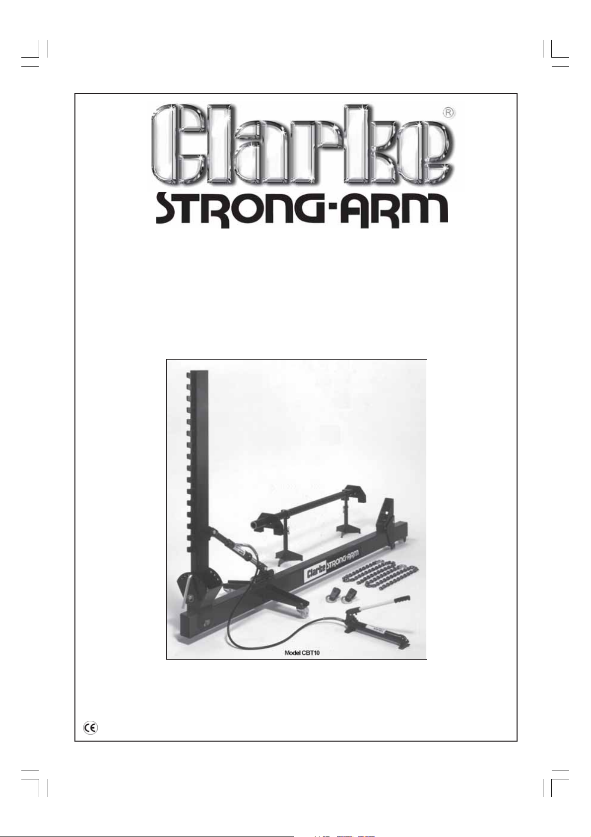
TON BODY
10
CB10 & CBT10
STRAIGHTENER
Model Nos.
OPERATING & MAINTENANCE
INSTRUCTIONS
1
0201
Page 2
Thank you for purchasing this CLARKE STRONGARM 10Ton Body Straightener, which is designed for
use by the home mechanic and professionals alike.
Before use, please read this leaflet thoroughly and follow the instructions carefully, in doing so you will
ensure the safety of yourself and that of others around you, and you can look forward to the
product giving you long and satisfactory service.
GUARANTEE
This CLARKE product is guaranteed against faulty manufacture for a period of 12 months from the
date of purchase. Please keep your receipt as proof of purchase. This guarantee is invalid if the
product is found to have been abused or tampered with in any way, or not used for the purpose for
which it was intended.
Faulty goods should be returned to their place of purchase, no product can be returned to us without
prior permission. This guarantee does not effect your statutory rights.
CONTENTS Page
General Safety Precautions .................................................................. 2
Features & Specifications ...................................................................... 3
How to identify the type of damage ................................................... 4
How to measure the extent of damage .............................................. 5
How to repair chassis damage ............................................................. 5
How to repair unitised bodies ............................................................... 7
Parts list & diagrams ........................................................................... 10 -11
GENERAL SAFETY PRECAUTIONS
As with all machinery, there are certain hazards involved with their operation and use. Exercising
respect and caution will considerably lessen the risk of personal injury. Ho wever, if normal saf ety
precautions are overlooked or ignored, personal injury to the operator or damage to property may
result.
1. READ AND BECOME FAMILIAR with the entire manual. Learn the MACHINES’ applications and
limitations as well as the specific potential hazards peculiar to it.
2. CHECK DAMAGED PARTS before using the machine. Any damaged component, should be
checked to ensure it will operate properly and perform its intended function correctly. Check for
breakage of parts, mountings, and any other condition that may affect its operation.
A damaged part should be properly repaired or replaced.
3. KEEP WORK AREA CLEAN. Cluttered areas invite accidents.
4. DON’T FORCE MACHINE. It will do a better and safer job at the rate for which it was designed.
5. KEEP VISITORS AWAY. All visitors, particularly children, should be kept a safe distance from the
work area, especially whilst operating the unit.
6. Before working on a vehicle, and before making any attachments, ensure the vehicle is well
supported and COMPLETELY STABLE.
REMEMBER, that when pulling, there is always the possibility of a fixture slipping, or a body part
failing, which could cause the vehicle to jolt suddenly. If the vehicle is not adequately supported
it could fall with possible serious consequences.
7. Do not modify the machine in any way.
8. Never use anextension handle to operate the pump.
2
Page 3
FEATURES and SPECIFICATIONS
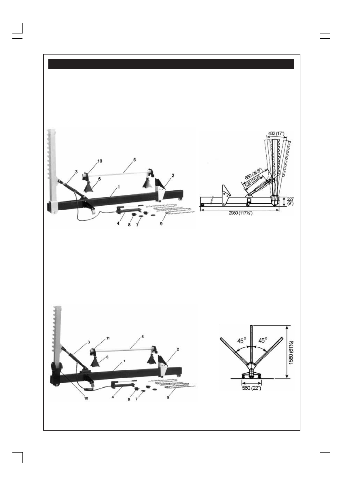
Model CB10 comprises the following:
1. Main Frame Assy
2. Multi-position Anchor Post
3. 6” Stroke Hydraulic Ram (10 Ton capacity)
4. Manual Pump
5. Cross Tube
Weight - 179kg (480lbs)
Part No. 7616025
6. 2 pcs Support Stand
7. 2 pcs Pull Ring
8. 2 pcs Pull Clamp
9. 6Ft Chain with 3/8” Hook
10. 2 pcs Under Body Support Clamp
Model CB10T comprises the following:
1. Main Frame Assy
2. Multi-position Anchor Post
3. 6” Stroke Hydraulic Ram (10 Ton capacity)
4. Manual Pump
5. Cross Tube
Shipping weight -191kg (420lbs)
Part No. 7616030
The Tilting post gives the machine far greater flexibility, in that pulls can be exerted at a variety of
angles, without necessarily adjusting the anchor points
6. 2 pcs Support Stand
7. 2 pcs Pull Ring
8. 2 pcs Pull Clamp
9. 6Ft Chain with 3/8” Hook
10. Tilting Support
11. 2 pcs Under Body Support Clamp
3
Page 4
HOW TO IDENTIFY THE TYPE OF THE DAMAGE
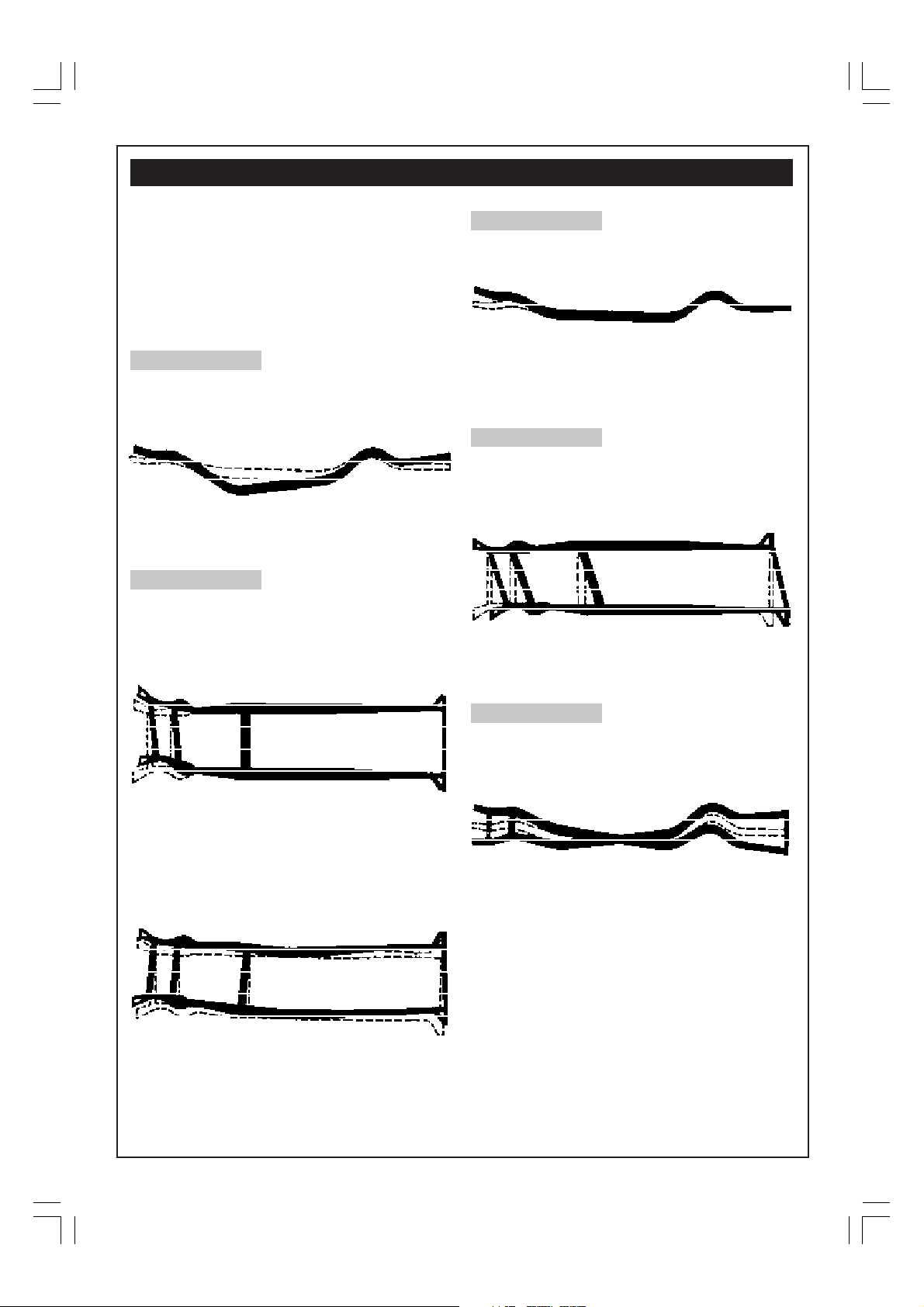
Chassis damage can usually be grouped into five
basic types of damage, described as SAG, SWAY,
KICK-UP, DIAMOND and TWIST,
Even though chassis are made in many ways
(such as ladder, offset, X-type etc.), collision
impact will distort the chassis, or parts of it,
regardless of construction.
I. SAG
When hit from the front or rear, the chassis can
sag like a hammock and then look like this:
Side view of sag
2. SWAY
Often when hit from the side, either in the middle
or at one end, the chassis may develop sway
looking like this:
3. KICK-UP
Quite often with direct front or rear end damage,
only a part of the chassis will kick-up like this:
Side View of Kick-up
Kick-up on Unitized Bodies is more like SAG. There
is generally only only one major bend in the floor
pan.
4. DIAMOND
Chassis’ built with two parallel side rails may get
pushed out of square when hit on one corner.
Then they become diamond shaped and look
like this:
Top view of Diamond
Hour glass, Unitised, or X-type chassis seldom “go
diamond”
Top View of Sway
Or like this:
Top View of Sway
Sway in Unitised Bodies doesn’t bend the entire
body. Instead only one part of the body will be
moved out of line.
5. TWIST
Sometimes the chassis will twist when the car goes
into a ditch, over a curb, etc., and will took like
this:
Side view of twist
These are the five classifications of chassis
damage. But remember, you will often find two
or more in the same job such as SAG and KICKUP. In some cases with front end damage the front
cross member or engine mounting will roll under
in addition to other types of chassis damage.
NOW that we know the types of chassis damage,
how do you determine if the chassis is bent? First,
if the car looks as if it has had a hefty jolt, get
underneath and LOOK AT THE CHASSIS. Are there
any places where the metal is torn? Are there
any places where the metals wrinkled? Does the
chassis look out of shape or bent? lf the answer
to ANY or ALL of these questions is yes, the
chances are that the chassis is bent.
4
Page 5
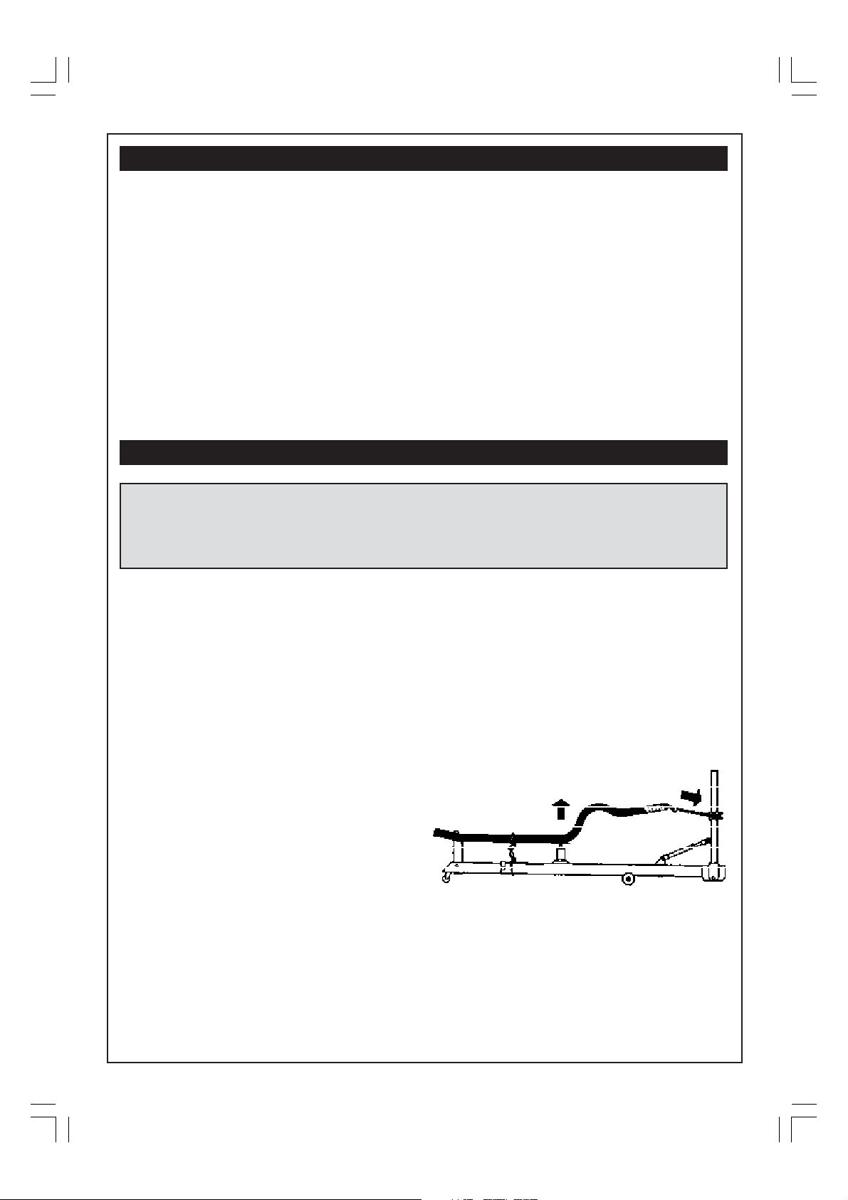
HOW TO MEASURE THE EXTENT OF THE DAMAGE
Before you begin work with your Body
Straightener, it is vital that you determine how
extensive the damage is.
To do this, get the car up off the ground, lie under
the structure and thoroughly inspect.
Measurements should be taken to see how far
the damaged sections are out of alignment.
These measurements can be made with a
Trammel Gauge, or a tape measure.
A simple method is to drop a plumb bob from
identical points from either side of the chassis,
marking them, in chalk, on the floor below.
Measure various points diagonally.
A perfect chasis will produce identical readings,
whereas a difference in measurement indicates
HOW TO REPAIR CHASSIS DAMAGE
CAUTION!
USE ONLY THE HYDRAULIC SET SUPPLIED WITH YOUR BODY STRAIGHTENER.
Use of different Hydraulic Set or handle may damage unit.
In such cases warranty claims will be void.
The idea of straightening chassis damage is to
exert a force in the reverse direction to that of
the collision impact.
the body/chassis has moved in some way.
From these measurements, determine where and
how the distortion has occurred.
Remember, it is your job to restore the damaged
sections back to the original factory
specifications. Therefore, it is important to work
from chassis dimension charts, so that you know
exactly what the original dimensions were. There
is no point in making a pull if you do not know
how far you can pull and when to stop. Take time
to examine the damage, note the direction of
the impact, and then plan your pull. Proper
planning will save you time when it comes to
actual pulling.
method is to weld a plate to the chassis from
which pulls can be made. The plate may later
be removed.
Your work will be made much easier by taking off
any interfering parts (wheels, bumpers grills, etc.),
so that you can see as well as get at the damage.
In cases where parts are unrepairable and must
be replaced, they should be removed first! In front
end damage it may become necessary to
remove upper or lower control arms, anti-roll bars,
etc. to eliminate excessive spring back.
Where major body damage occurs, rough out
the body metal first. DON’T REMOVE BODY BOLTS
unless absolutely necessary. Do as much body
roughing out as you can whilst working on the
chassis.
If possible, correct any body damage in unison
with chassis straightening. This will save time and
effort and will make it easier to align the body
with the chassis.
The chassis and body should always be
overcorrected to allow for spring-back.
Hammering or heating the metal will help relieve
the stress and help eliminate excessive
springback.
When there is no clearance between the chassis
and the body, the floor may be pried up to allow
anchoring of the chain or an opening in the floor
made that can later be welded shut. A prefered
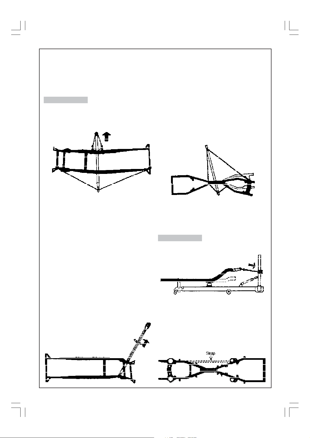
SAG
To repair SAG put the main beam of the Body
Straightener under the car and chain the chassis
to the beam. Place a Hand Jack between the
beam and the chassis at the center of the SAG
area and jack upward whilst also pulling as shown
in the sketch below:
Always use a combination of push AND pull when
correcting sag. If you do not, you may end up
with one chassis rail shorter than the other. It both
rails are sagged, straighten one at a time, then
check with gauges to see that the chassis is back
in line. If it isn’t repeat this process.
Keep the hold-down chains on the chassis as far
apart from the jack as you can. This will make
straightening easier. Where there are bad
buckles, heat the chassis.
5
Page 6
Use a steel plate between the jack and the
chassis to spread the load, otherwise the jack may
collapse the chassis. Blocks may be inserted inside
the channel-type chassis to help prevent the
bottom flange from being crushed. To keep the
jacks stable place a block of wood under the
base when jacking from the main beam.
SWAY
To correct SWAY damage, hook up the Body
Straightener as shown in the diagram below. Side
anchoring from the Anchor Post at either side of
the damage is required in center-sway
straightening.
chassis as a temporary support. When you have
finished pulling, cut off the plate.
Occasionally on SWAY pulls you may find that the
Body Straightener lifts off the floor. Put a block of
wood between the beam and the chassis to hold
the Body Straightener in position.
Rear end SWAY can be pulled out in the same
way.
One of the SWAY corrections which may seem
puzzling at first is that of the X or “hourglass’’
chassis. Almost always, these are bent only on
one end and the center box tube remains
aligned with the other end, as shown in the
diagram below. These may be corrected with a
hookup similar to the one shown here:
In cars with low door sills, it may be necessary to
put a block of wood between the chain and floor
panel to protect the body metal.
Here is a good time to remember several notes
of caution concerning the use of chains.
• Do not pull chains around sharp edges.
• Do not heat chains with the torch.
• Do not bolt links together.
• To be on the safe side, place an old tarpaulin
or cover over the chain when pulling, so that
if a link does let go, the snap back will be
smothered
Keep a continuous check as you proceed. You
should pull a little beyond center to allow for
spring back in the metal. Make a final check after
tension has been released.
For front end SWAY, hook up the Body Straightener
in the manner shown below.
Wedge the Anchor Post of the Body
Straightener against the chassis. If
you can’t find anything to anchor
against, wrap chain around the
chassis and the post, or weld a
piece of steel plate to the
If the car is raised high enough, the chains will
slant down and clear the body panels - bumper,
valance etc. The drawing shows only one
hookup, however, variations of this may be made
to suit the particular conditions of damage.
KICK-UP
To repair KICK-UP, or ROLL-UNDER, hook up the
Body Straightener as shown below:
Don’t forget to measure when you have finished
pulling to ensure that the rails have returned to
their proper dimension.
When pulling from front to rear as shown in the
sketch below, weld a strap on the chassis to keep
from stretching one side of the chassis longer than
the other. (This applies to the “hourglass type”
chassis).
6
Page 7
DIAMOND
Diamond chassis’ can be straightened by using
the same general hook up as for front end sway,
except that due to the extra length (pulling
diagonally), a chain is connected to the anchor
post as shown below.
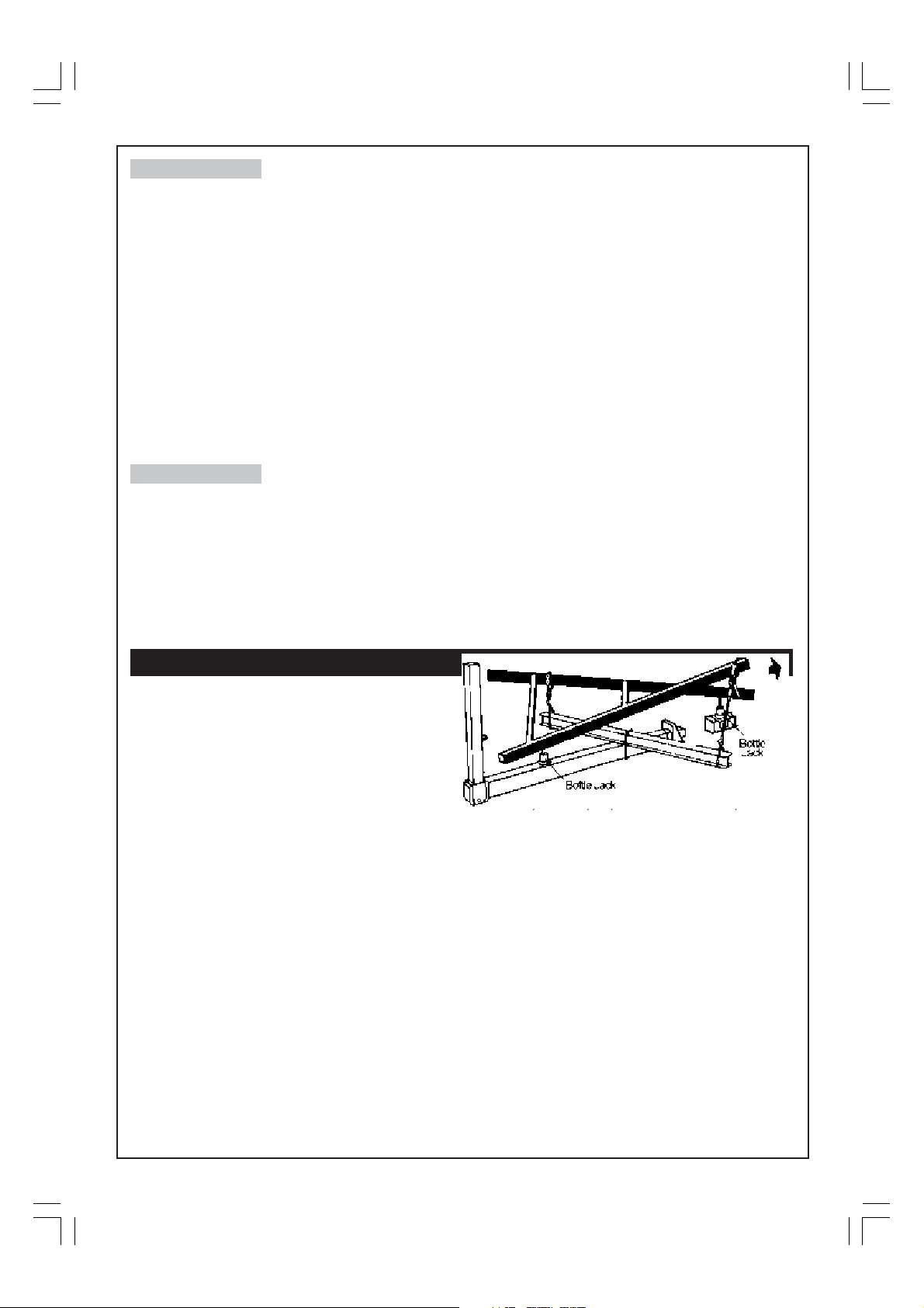
TWIST
Always remove twist after all other chassis
damage is corrected.
Place the machine diagonally under the car, with
an 8ft section of heavy I-beam balanced on top
of the frame, forming a ‘cross’ below the car.
Chain the I-beam to the frame to prevent it from
lifting and sllipping.
Chain the high points of the chassis to the I-beam
and place bottle jacks as shown in the diagram
below.
Now proceed to jack up the bottle jacks...first
one, then the other. DO NOT push the whole way
on one rail as you may cause it to SAG. If the
damage is simple twist, there should not be any
buckles.
HOW TO REPAIR UNITISED BODIES
IT IS IMPORTANT TO USE THE PROPER TECHNIQUE.
The repair of unitised bodies follows basic body
repair methods and a knowledge of metal
working is absolutely essential. A combination of
methods is always needed in these repairs, since
the,”heat-’n-beat” method alone will not always
succeed.
The techniques used are a combination of:
I. Heavy external pulling
2. Use of Hydraulic Rams (such as Clarke’s 10Ton
Hydraulic Body Repair Kit - CS10TK - see your
Clarke dealer)
3. Use of heat
4. Use of hammer and dolly block
5. Cutting out buckled sections or reinforcing
members
Heavy external pulls are a must for all severe
unitised body damage, because THE IMPACT
WILL HAVE COMPRESSED THE BODY METAL - NOW
IT HAS TO BE PULLED BACK INTO PLACE.
Clarke Body Straighteners are designed as a
pulling machine for this reason.
Since there is no chassis, the whole job is
essentially a body repair. There is no separation
of work Into chassis repair followed by body repair.
The complete job is planned as one.
Large stationary machines which are ramp or pit
mounted do not offer easy access to the body.
A Clarke Body Straightener, with its practical
method of mounting the car on low stands, allows
easy access to all sections.
When pulling sheet metal, DO NOT APPLY ALL THE
FORCE IN ONE PLACE, AT ONE TIME.
Spread the restoring forces, pull at one place and
then, without shifting the setup, merely change
the attachment point and pull at another.
Hook-ups are fast simple and easy with the Body
Straightener as you can easily maneuvre the
equipment around the job.
7
Page 8
ROUGH OUT THE WORK
By this we mean the restoring of panels to
APPROXIMATE shape and dimension EVEN
THOUGH THEY MAY LATER BE REPLACED.
Panels should be roughed out before any cutting
is done, otherwise adjacent structures to which
the panel is welded may retain their damaged
contours after cutting. If this occurs, the
replacement panels will not fit and it is a losing
battle trying to obtain a proper joint.
To illustrate:
When a wing is badly buckled, the wheel arch
generally is also damaged. If the wing is cut loose
from the wheel arch before a pull is exerted on it,
the wheel arch will remain buckled and distorted.
It will then be extremely difficult to straighten this
area so that the replacement panel can be
welded or bolted to it. Therefore, work the
damaged panels back into shape and dimension
before attempting any cutting or unbolting
operations
CHECK THE WORK
As repairs proceed, keep track of your progress
by continually checking dimensions, window and
door openings, etc.
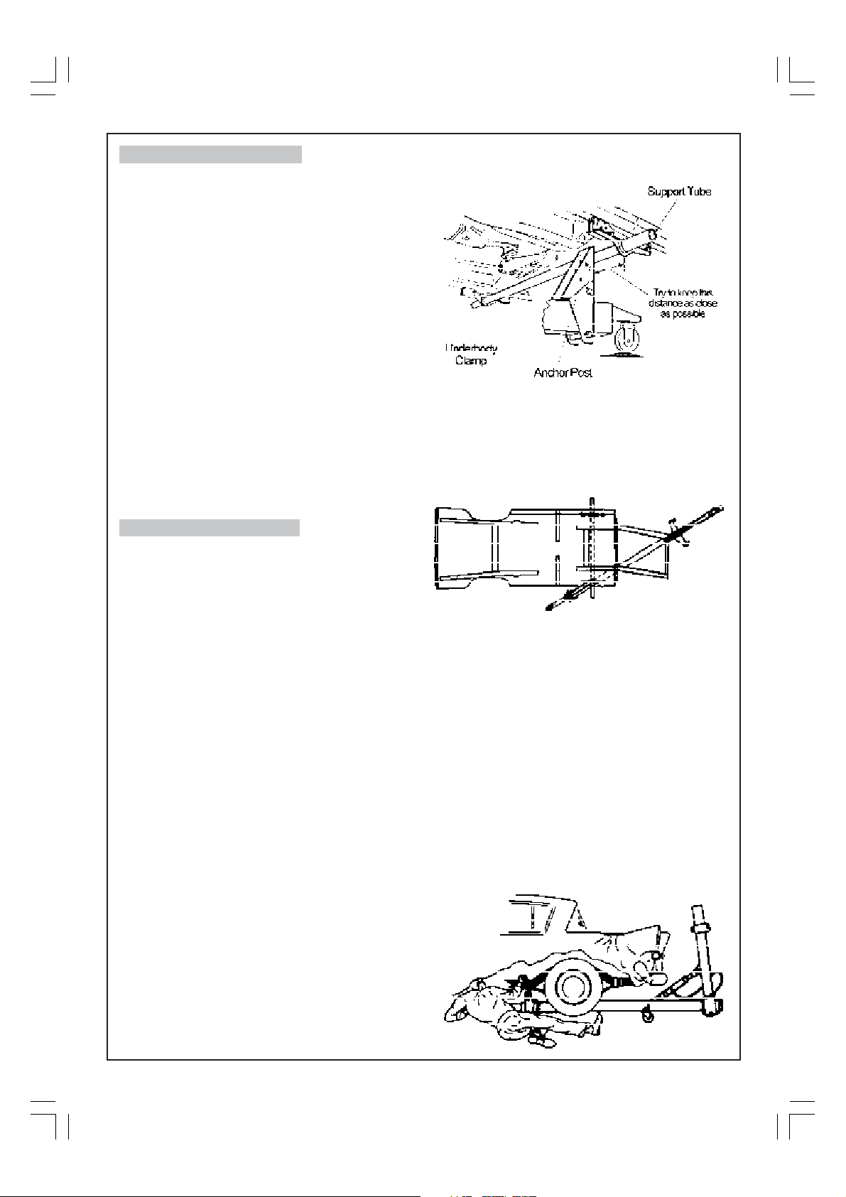
The Anchor Post can push against the Underbody
Clamp and tube, as shown...
The tube will help stabilise the underbody clamp and avoid
twisting the welded seam
...or a Chain can be used around the tube to
attach to the Anchor Post as shown below.
With a unitised body, it is sometimes necessary to
overcorrect because of the stiffness of the
construction, and a degree of ‘spring back’, but
it is important not to go too far as this can cause
further damage.
One of the difficulties often presented in the repair
of unitised bodies is that of anchoring the
machine to the body. Since there is no longer a
heavy chassis against which to anchor or pull,
this can be a problem. However, the use of the
Underbody Clamps will provide a firm base and
will cope with many of the situations generally
found.
This Clamp fastens to the under body seam which
runs the length of most modern cars, and the
cars’ jacking points are usually to be found here.
The clamp should be fastened In the area of the
door pillar. It may be moved forward or backward
as required.
One clamp may be used, although greater
holding power may be obtained by using one
clamp on each side of the body and placing the
Support Tube between them as shown in the
following diagram.
The following illustrations are examples of typical
Body Straightener Hook-ups for repairing
damaged unitised vehicles.
With all unitised body construction, special
attention must be given to certain load-bearing
or structural members such as chassis side
members, inner wheel arch panels, cross
members, the floor pans that form a part of the
cross members or box sections. These must be
brought back to the equivalent of their original
condition, which means returned to original
shape without wrinkles or excess thinning of the
metal.
The first step in making any hook-up is to anchor
the Body Straightener securely to the chassis....
8
Page 9
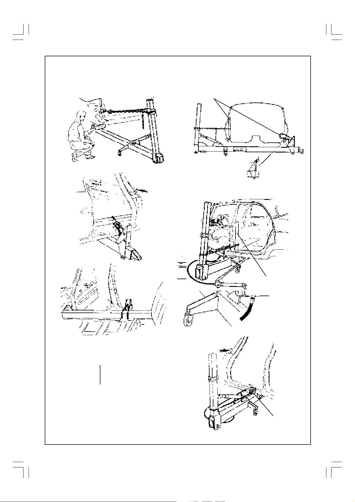
....or to the body using Underbody Clamps as
previously shown.
Other typical ‘hook ups’ are illustrated below.
Next, a pulling attachment is secured to the
damaged part as shown below.
Blocks of wood to spread load
and avoid unnecessary
damage.
Flap, cut in door sill so that chain or insert
may be entered. The insert is connected
to the mast and a pull exerted.
Block of wood to spread
load and avoid
unnecessary damage.
Wood can be shaped to
contour of work where
necessary.
Pull Clamp
attached to door sill
9
Page 10
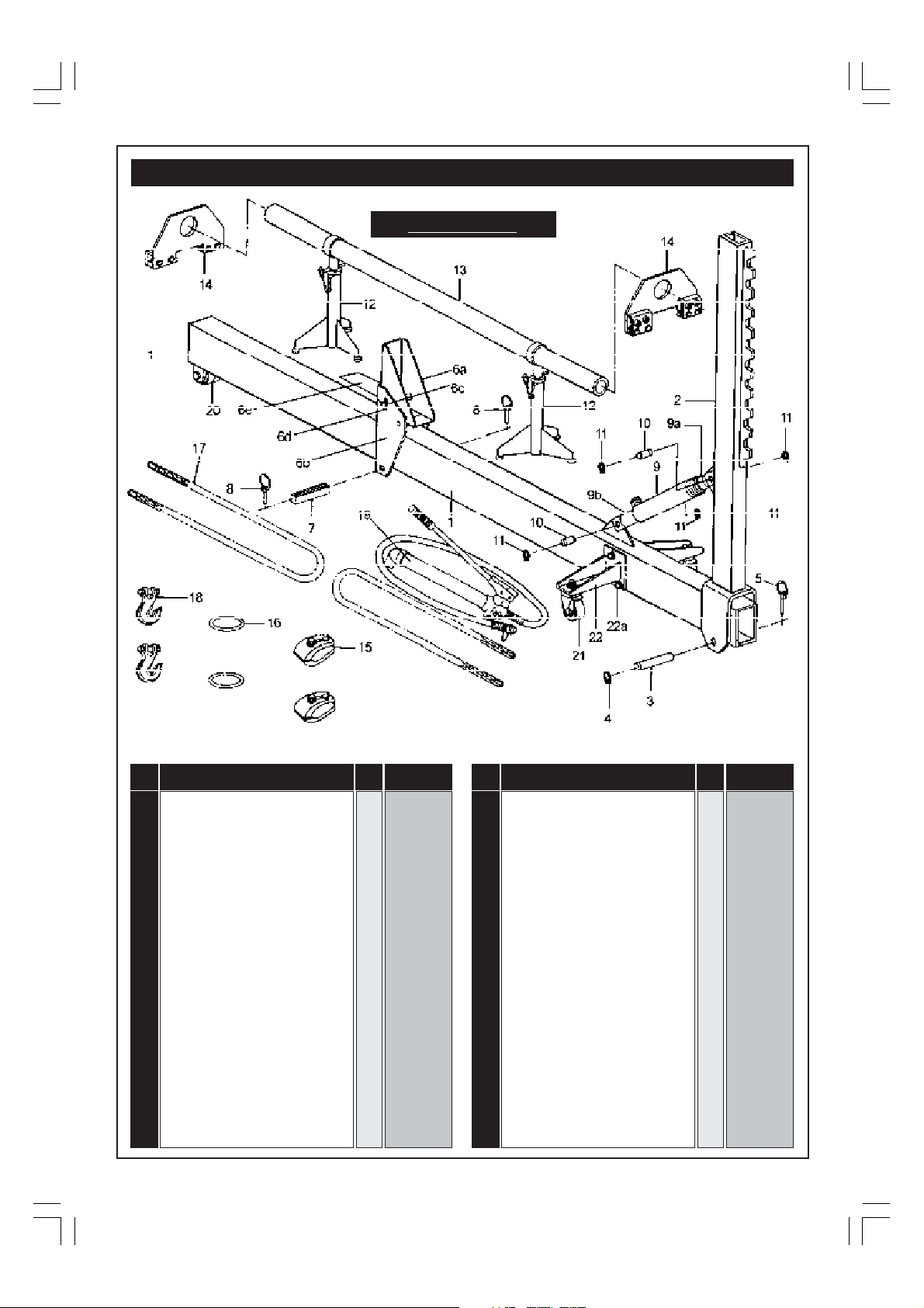
PARTS LIST & DIAGRAM
Model CB10
No. Description Qty Part No.
1 Main Beam 1 CB1001
2 Mast 1 CB1002
3 Main Beam Locating Pin 1 CB1003
4 Circlip 1 CB1004
5 Locking Pin 1 CB1005
6a Anchor Post Upper Bracket 1 CB1006A
6b Anchor Post Lower Bracket 1 CB1006B
6c Anchor Post Locating Pin 1 CB1006C
6d Locating Pin Clip 2 CB1006D
6e Plate Spring 1 CB1006E
7 Stop Block 1 CB1007
8 Locking Pin 2 CB1008
9 10 Ton Ram 1 CB1009
9a Ram End Piece (Female) 1 CB1009A
9 Ram End (Male) 1 CB1009B
No. Description Qty Part No.
10 Ram Locating Pin 2 CB1010
11 Circlip 4 CB1011
12 Support Stand 2 CB1012
13 Cross Tube 1 CB1013
14 Underbody Support Clamps 2 CB1014
15 Pull Calmps 2 CB15
16 Pull Ring 2 CB1016
17 6ft x 3/8” chain 2 CB1017
18 3/8” hook 2 CB1018
19 10 Ton Hydraulic Pump 1 CB1019
20 Fixed Wheel Assy. 1 CB1020
21 Castor Assy. 2 CB1021
22 OutRigger 2 CB1022
22a Outrigger Bolt 6 CB1022A
10
Page 11
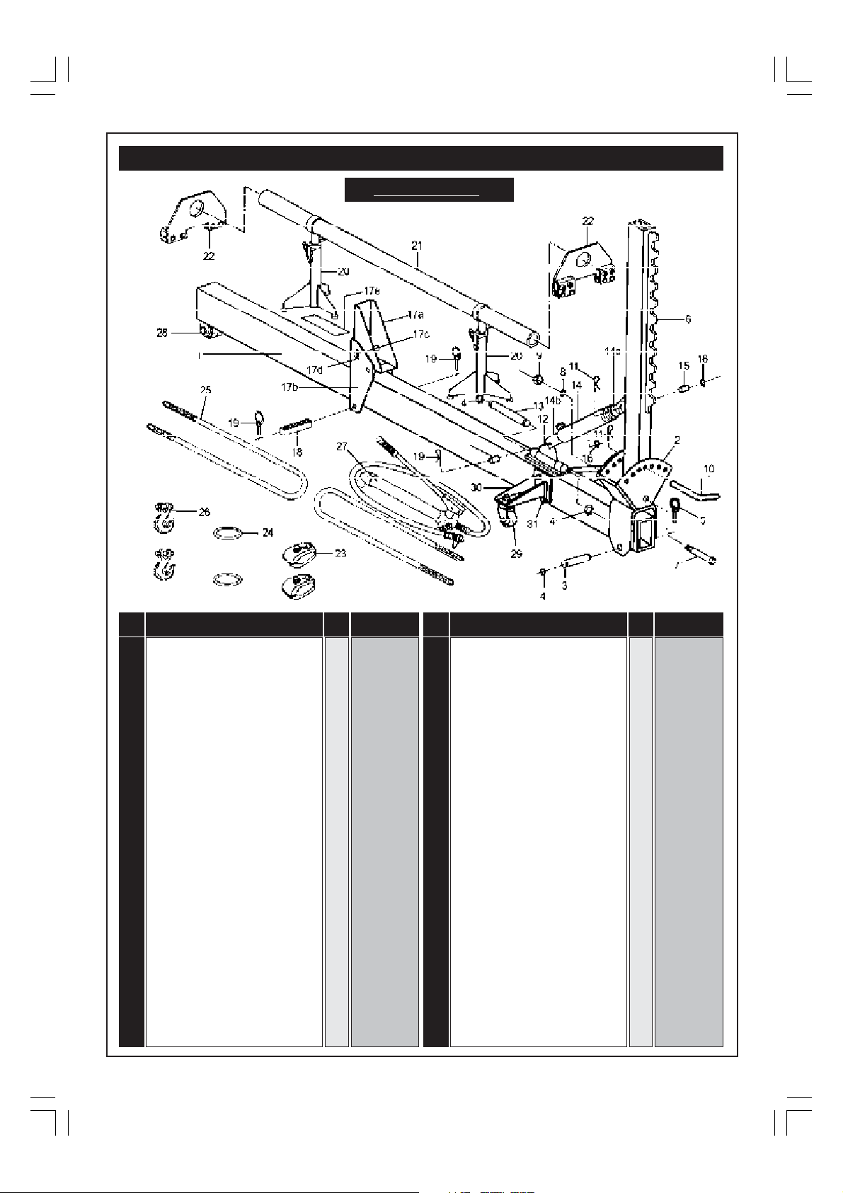
PARTS LIST & DIAGRAM
Model CBT10
No. Description Qty Part No.
Main Beam 1 CBT1001
1
2 Tilting Support 1 CBT1002
3 Main Beam Locating Pin 1 CBT1003
4 Circlip 3 CBT1004
5 Locking Pin 1 CBT1005
6 Mast 1 CBT1006
7 Bolt 3/4” x 7” 1 CBT1007
8 Spring Washer 1 CBT1008
9 Nut 3/4” 1 CBT1009
10 Mast Locking Pin 1 CBT1010
11 ‘R’ Clip 3 CBT1011
12 Lower Ram Bracket 1 CBT1012
13 Lower Ram Bracket Pin 1 CBT1013
14 10 Ton Ram 1 CBT1014
14a Ram End (Female) 1 CBT1014A
14b Ram Ensd (Male) 1 CBT1014B
15 Pin 2 CBT1015
16 Circlip 2 CBT1016
17a Anchor Post Upper Bracket 1 CBT1017A
No. Description Qty Part No.
17b Anchor Post Lower Bracket 1 CBT1017B
17c Anchor Post Locating Pin 1 CBT1017C
17d Locating Pin Clip 2 CBT1017D
17e Plate Spring 1 CBT1017E
18 Stop Block 1 CBT1018
19 Pin 2 CBT1019
20 Support Stand 2 CBT1020
21 Cross Tube 1 CBT1021
22 Underbody Support Clamps 2 CBT1022
23 Pull Clamps 2 CBT1023
24 Pull Ring 2 CBT1024
25 6ft x 3/8” Chain 2 CBT1025
26 3/8” Hook 2 CBT1026
27 !0 Ton Hydraulic Pump 1 CBT1027
28 Fixed Wheel Assy 1 CBT1028
29 Outrigger Castor Assy 2 CBT1029
30 Outrigger 2 CBT1030
31 Outrigger Bolt 6 CBT1031
11
 Loading...