

Page 1

ANGLE HEAD DIE GRINDER
MODEL No. CAT83
OPERATING & MAINTENANCE
INSTRUCTIONS
Part No. 3110815
0504
Page 2
PARTS & SERVICE CONTACTS
Please contact your nearest dealer, or
CLARKE International, on one of the following numbers.
PARTS & SERVICE TEL: 020 8988 7400
PARTS & SERVICE FAX: 020 8558 3622
or e-mail as follows:
PARTS: [email protected]
SERVICE: [email protected]
- 7 -- 2 -
Employers are advised to refer to the HSE publication “Guide for Employers”.
All hand held power tools vibrate to some extent, and this vibration is transmitted to the
operator via the handle, or hand used to steady the tool. Vibration from about 2 to 1500
herz is potentially damaging and is most hazardous in the range from about 5 to 20 herz.
Operators who are regularly exposed to vibration may suffer from Hand Arm Vibration
Syndrome (HAVS), which includes ‘dead hand’, ‘dead finger’, and ‘white finger’. These
are painful conditions and are widespread in industries where vibrating tools are used.
The health risk depends upon the vibration level and the length of time of exposure to
it……in effect, a daily vibration dose.
Tools are tested using specialised equipment, to approximate the vibration level generated
under normal, acceptable operating conditions for the tool in question. For example, a
grinder used at 45° on mild steel plate, or a sander on softwood in a horizontal plane etc.
These tests produce a value‘a’, expressed in metres per second per second, which
represents the average vibration level of all tests taken, in three axes where necessary,
and a second figure ‘K’, which represents the uncertainty factor, i.e. a value in excess of
‘a’, to which the tool could vibrate under normal conditions. These values appear in the
declaration on page 7.
HAND-ARM VIBRATION
You will note that a third value is given in the specification - the highest measured reading
in a single plane. This is the maximum level of vibration measured during testing in one of
the axes, and this should also be taken into account when making a risk assessment.
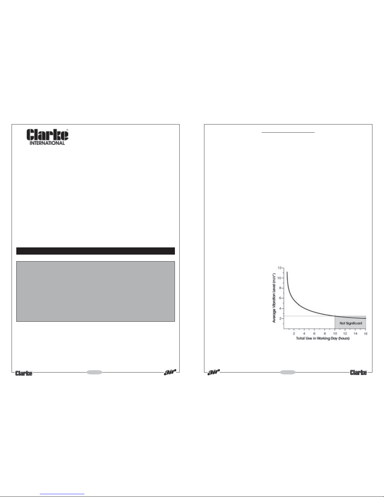
‘a’ values in excess of 2.5 m/s2 are considered hazardous when used for prolonged periods.
A tool with a vibration value of 2.8 m/s2 may be used for up to 8 hours (cumulative) per
day, whereas a tool with a value of 11.2 m/s2 may be used for ½ hour per day only.
The graph below shows the vibration value against the maximum time the respective tool
may be used, per day.
The uncertainty factor should
also be taken into account
when assessing a risk. The two
figures ‘a’ and ‘K’may be
added together and the
resulant value used to assess the
risk.
It should be noted that if a tool
is used under abnormal, or
unusual conditions, then the
vibration level could possibly
increase significantly. Users must
always take this into account
and make their own risk
assessment, using the graph as
a reference.
Some tools with a high vibration value, such as impact wrenches, are generally used for a
few seconds at a time, therefore the cumulative time may only be in the order of a few
minutes per day. Nevertheless, the cumulative effect, particularly when added to that of
other hand held power tools that may be used, must always be taken into account when
the total daily dose rate is determined.
Page 3
SAFETY PRECAUTIONS
IMPORTANT
Failure to follow these precautions could
result in personal injury, and/or damage to
property.
❐ When operating this tool, ALWAYS wear:
a. approved impact resistant SAFETY
GOGGLES. (Eye glasses are NOT
safety glasses)
b. a DUST MASK
c. EAR DEFENDERS
d. a good pair of INDUSTRIAL GLOVES
❐ ALWAYS disconnect the tool when not
in use, and before carrying out any
maintenance
❐ ALWAYS keep a safe distance between
yourself and other people when using
the tool.
❐ ALWAYS maintain the tool with care. Keep
it clean for best and safest performance.
❐ NEVER wear ill fitting clothing, remove
watches and rings.
❐ Quick change couplings should not be
located at the tool. They add weight
and could fail due to vibration.
❐ DO NOT over-reach. Keep your proper
footing and balance at all times.
❐ DO NOT force or misuse the tool. It will
do a better and safer job at the rate for
which it was designed.
❐ DO NOT abuse hoses or connectors.
NEVER carry a tool by the hose, or yank
it to disconnect from the air supply. Keep
hoses away from heat, oil and sharp
edges. Check hoses for leaks or worn
condition before use, and ensure that
all connections are secure.
❐ DO NOT exceed 90 PSI at the tool.
❐ DO NOT modify the tool in any way.
❐ DO NOT remove any labels. Damaged
labels should be replaced.
❐ This tool vibrates with use. Vibration may
be harmful to your hands or arms. Stop
using the tool if discomfort, a tingling
feeling or pain occurs. Seek medical
advice before resuming use.
❐ ALWAYS use screens to protect people
in the vicinity from flying debris.
❐ NEVER point the tool at anyone.
- 3 -
Please read these instructions
carefully before operating the tool
Thank you for purchasing this CLARKE Angle
Head Die Grinder, designed for use when
carrying out ‘smart’, localised repairs to
vehicle bodywork etc.
Before using the Grinder, please read this
leaflet thoroughly and follow the instructions
carefully, in doing so you will ensure the
safety of yourself and that of others around
you, and you can look forward it giving long
and satisfactory service.
GUARANTEE
This CLARKE product is guaranteed against
faulty manufacture for a period of 12
months from the date of purchase. Please
keep your receipt as proof of purchase. This
guarantee is invalid if the product is found to
have been abused or tampered with in any
way, or not used for the purpose for which it
was intended.
Faulty goods should be returned to their
place of purchase, no product can be
returned to us without prior permission. This
guarantee does not effect your statutory
rights.
WARNING
Compressed air can be
dangerous. Ensure that you are
thoroughly familiar with all
precautions relating to the use
of compressors and
compressed air supply.
ACCESSORIES
A wide range of Airline accessories is available, including Filter/Regulators, Lubricators,
High Pressure Hoses from 5 to 100 Metres, etc. Contact your CLARKE dealer for further
information, or CLARKE International Sales Department on 01992 565300
SPECIFICATIONS
Air Inlet 1/4" BSP
Min. Hose Size (ID) 8mm (5/16")
Ave. Air Consumption 10 CFM
Max. Speed 25,000 RPM
Air Pressure Max. 90 PSI (6.1 BAR)
Vibration Level >2.5m/s
2
Part No. 3110815
- 6 -
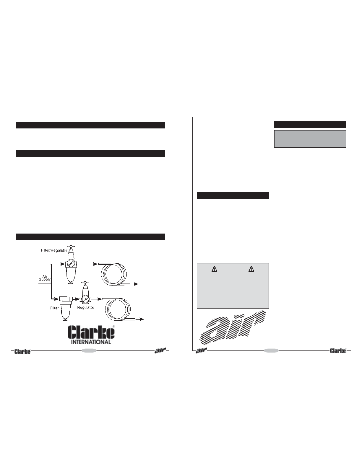
RECOMMENDED AIR SUPPLY CONNECTION
Please note that the details and specifications contained herein, are correct at the time of going to
print. However, CLARKE International reserve the right to change specifications at any time without
prior notice. Always consult the machine’s data plate
Page 4
MAINTENANCE
Daily before use.
1. Drain water from air tank, air line and
compressor.
2. Check and clean, if necessary, the air
inlet gauze filter .
3. Pour a few drops of CLARKE Air Line Oil
(approx 3cc), into the air inlet. This should
be carried out regardless of whether or
not an air line lubricator is used.
If an Air line lubricator is NOT used, this
procedure should be repeated after
every two to three hours of use.
If the Grinder is to be stored, or is idle for
longer than 24 hours, run a few drops of
Clarke Air Line Oil into the air inlet, and run
the tool for 5 seconds in order to lubricate
the internal parts.
For lubricating the air motor when in
operation, an air line lubricator should be
used, with Clarke Air Line Oil, adjusted to 2
drops per minute.
Clarke Air Line Oil is available from your
CLARKE dealer, part no. 3050825.
Be aware that factors other than the tool
may effect its operation and efficiency, such
as reduced compressor output, excessive
drain on the airline, moisture or restrictions in
the line, or the use of connectors of improper
size or poor condition which will reduce air
supply.
Grit or gum deposits in the tool may also
reduce efficiency. This condition can be
corrected by cleaning the air strainer and
flushing out the tool with gum solvent oil,or
failing this, the tool should be dis-assembled,
thoroughly cleaned, dried and reassembled.
If the tool runs erratically or becomes
inefficient, and the air supply is sound,
dismantle the air motor and replace worn
or damaged parts, or take the tool to your
CLARKE dealer.
IMPORTANT:
The use of parts other than CLARKE
replacement parts may result in safety
hazards, decreased tool performance
and may invalidate your warranty.
AIR SUPPLY
Tools of this type, operate on a wide range
of air pressures. It is recommended that air
pressure to this tool does not exceed 90 PSI,
at the tool when running. Higher pressure
and unclean air, will shorten the tools’ life
because of faster wear, and could be a
safety hazard.
Water in the air line will cause damage to
the tool, ensure it is properly maintained at
all times.
The recommended procedure to connect
this tool to an air supply, is shown at fig. 2 on
page 5.
The air inlet used for connecting air supply,
has a standard ¼” BSP thread.
Line pressure, or hose inside diameter, should be
increased to compensate for unusually long air
hoses (over 10m). Minimum hose diameter
should be 8mm (5/16") ID., and fittings should
have the same inside dimensions.
ASSEMBLY
With the air supply turned OFF, connect the
hose of the Grinder to your airline and then
insert the spindle of the tool to be used into
the collet of the drive spindle, tightening the
collet nut using the two spanners provided.
Your Grinder is now ready for use.
OPERATION
Turn ON the air supply, and check for air
leaks. If any are apparent, rectify before
proceeding.
Hold the tool so that the operating lever is
in the palm of one hand. With the airline
pressure set to 90 lbf/in2 (6.1bar), push the
spring loaded safety latch, mounted in the
operating lever, forward. This allows the
operating lever to be depressed, starting
the tool .
To stop the tool, release the trigger. The
safety latch will automatically lock the
operating lever preventing further operation
intil it is again pushed forward.
NOTE: The speed of the tool is factory set to
25,000RPM, and should not need adjusting.
- 4 -
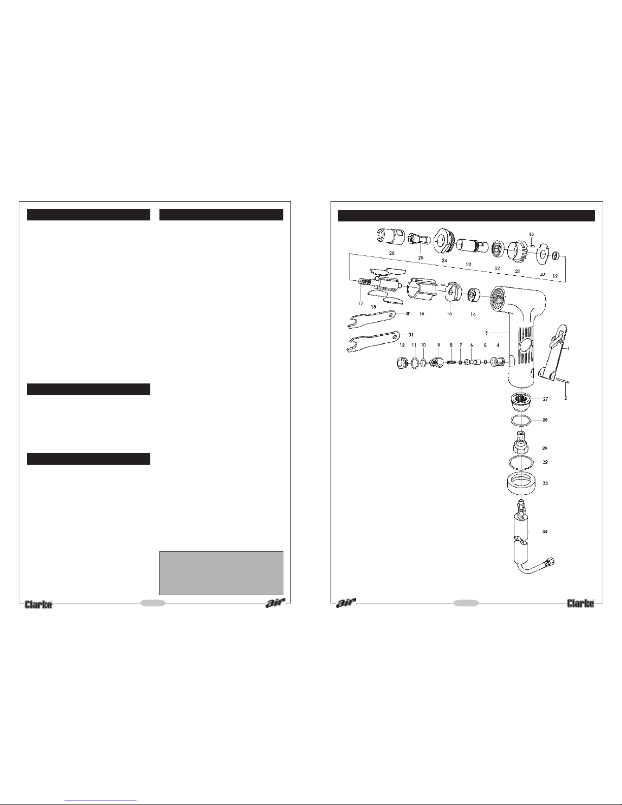
PARTS LIST & DIAGRAM
No. Description Part No.
1 T hrottle Lever 0308AH001
2 Spring Pin 0308AH002
3 Housing 0308AH003
4 Valve Bushing 0308AH004
5 O-Ring 0308AH005
6 Valve Stem 0308AH006
7 O-Ring 0308AH007
8 Valve Spring 0308AH008
9 A ir Controller 0308AH009
10 O-Ring 0308AH010
11 O-Rin 0308AH011
12 Valve Screw 0308AH012
13 Bearinfg 0308AH013
14 End Plate 0308AH014
15 Pin 0308AH015
16 Cylinder 0308AH016
17 Rotor 0308AH017
18 Blade 0308AH018
19 Collar 0308AH019
20 Steel Plate 0308AH020
21 Front Plate 0308AH021
22 Beariong 0308AH022
23 Spindle 0308AH023
24 Lock Ring 0308AH024
25 Collet 0308AH025
26 Collet Nut 0308AH026
27 Exhaust Sleeve 0308AH027
28 O-Ring 0308AH028
29 Air Inlet 0308AH029
30 11mm Wrench 0308AH030
31 17mm Wrench 0308AH031
32 O-Ring 0308AH032
33 Clamp Ring 0308AH033
34 Air Hose Assy 0308AH034
- 5 -
 Loading...