

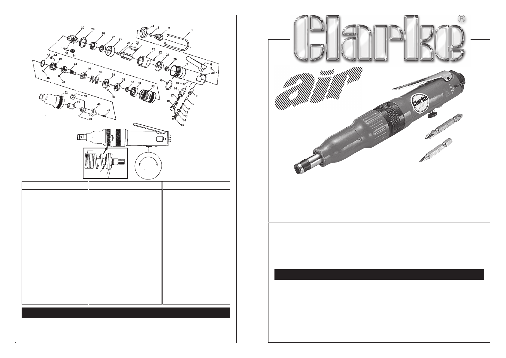
PARTS LIST
No Description Part No. No. Description Part No. No. Description Part No
1 Hanger 2001 20 Ball Bearing 2020 39 Spring 2039
2 Air Inlet 2002 21 End Plate 2021 40 Spring Seat 2040
3 O-Ring 2003 22 Pin 2022 41 Clutch Spindle 2041
4 Exhaust Cover 2004 23 Cylinder 2023 42 Steel Ball 2042
5 Lever Pin 2005 24 Rotor Blade 2024 43 Dog 2043
6 Switch Lever 2006 25 Rotor 2025 44 Plug 2044
7 Rotor Case 2007 26 Front Plate 2026 45 Steel Ball 2045
8 O-Ring 2008 27 Ball Bearing 2027 46 Dog Retainer 2046
9 Bush 2009 28 Ball Bearing 2028 47 Centre Spring 2047
10 Valve Stem 2010 29 Washer 2029 48 Anvil 2048
11 O-Ring 2011 30 Planet Cage 2030 49 Steel Ball 2049
12 Val;ve Spring 2012 31 Planet Wheel 2031 50 Steel Ball Collar 2050
13 O-Ring 2013 32 Planet Pin 2032 51 Bush 2051
14 Rev. Retainer 2014 33 Internal Gear 2033 52 Clutch Case Nut 2052
15 Valve Screw 2015 34 Ball bearing 2034 53 Retainer Washer 2053
16 Bush 2016 35 Collar 2035 54 Washer 2054
17 Reverse Spring 2017 36 Adjuster Nut 2036 55 Spring 2055
18 Reverse Valve 2018 37 Steel Ball 2037 56 Retainer 2056
19 Steel Ball 1/8" 2019 38 Adj. Nut Seat 2038 57 Ball Retainer 2057
ACCESSORIES
A wide range of Airline accessories is available, including Filter/Regulators, Lubricators,
High Pressure Hoses from 5 to 100 Metres, etc. Contact your CLARKE dealer for further
information, or CLARKE International Spare Parts Department on 0181 558 6696.
REVERSIBLE SCREWDRIVER
CAT39
Part No. 3110439
Thank you for purchasing this CLARKE Air Screwdriver, designed for general workshop
and industrial use.
Before using the tool, please read this leaflet thoroughly and follow the instructions
carefully, in doing so you will ensure the safety of yourself and that of others around
you, and you can look forward it giving long and satisfactory service.
GUARANTEE
This CLARKE product is guaranteed against faulty manufacture for a period of 12
months from the date of purchase. Please keep your receipt as proof of purchase.
This guarantee is invalid if the product is found to have been abused or tampered
with in any way, or not used for the purpose for which it was intended.
Faulty goods should be returned to their place of purchase, no product can be
returned to us without prior permission.
This guarantee does not effect your statutory rights.
SAFETY PRECAUTIONS for AIR TOOLS
IMPORTANT
Failure to follow these precautions
could result in personal injury, and/or
damage to property.
1. ALWAYS wear approved impact resistant
safety goggles. (Eye glasses are NOT
safety glasses).
2. ALWAYS wear face or dust mask (where
dust is created), and ear defenders when
necessary.
3. ALWAYS disconnect the tool when not in
use, before changing accessories and
before carrying out any maintenance
4. ALWAYS have trigger in the OFF position
when connecting to an air supply.
5. ALWAYS keep a safe distance between
yourself and other people when using the
tool.
6. Maintain the tool with care. Keep it clean
for best and safest performance.
AIR SUPPLY
Tools of this type, operate on a wide range of
air pressures.
It is recommended that air pressure to this tool
does not exceed 90 PSI, at the tool when
running. Higher pressure and unclean air, will
shorten the tools’ life because of faster wear,
and could be a safety hazard.
Water in the air line will cause damage to the
tool. Ensure the tool is properly maintained at
all times. (See maintenance section) The
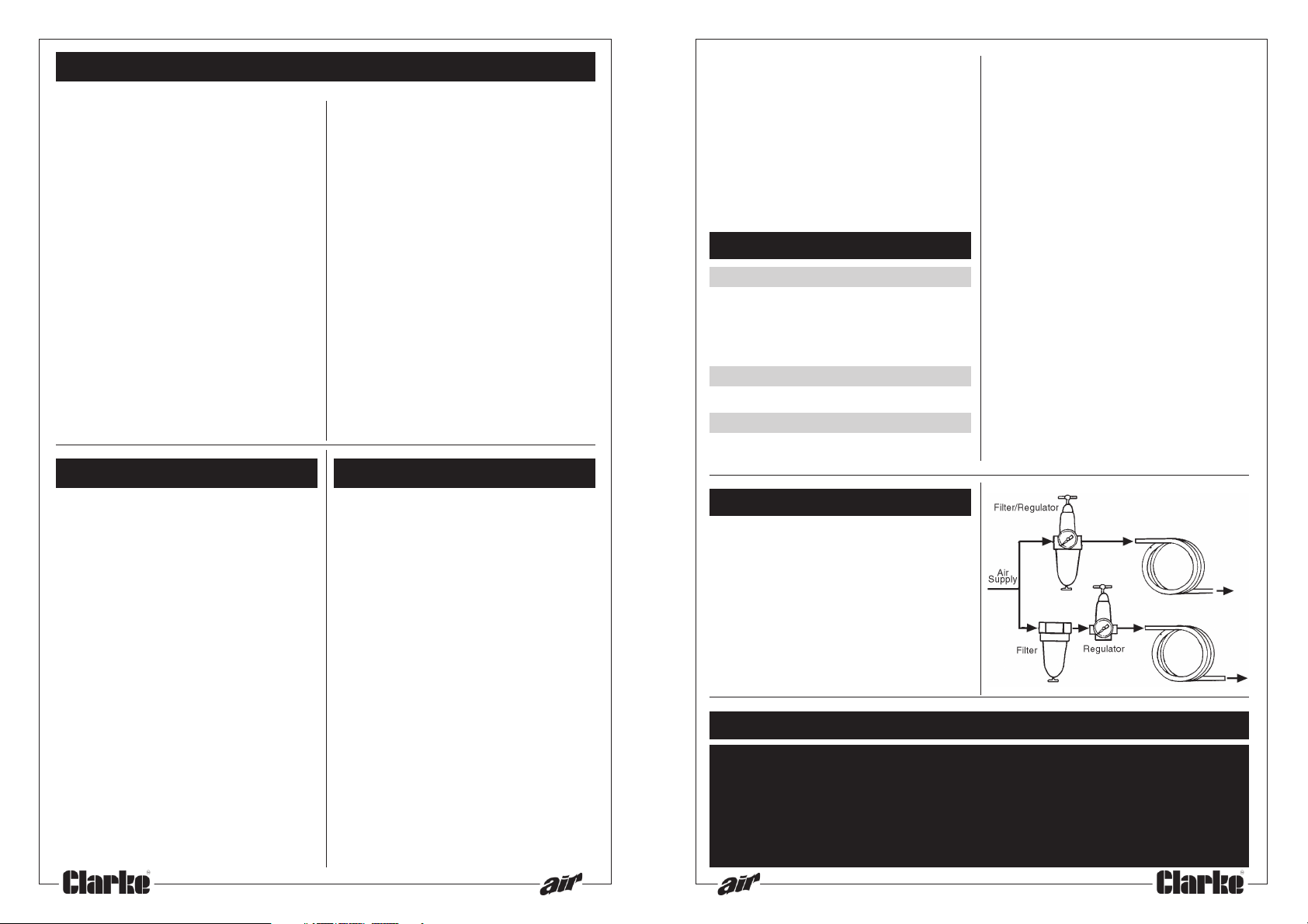
recommended procedure for connecting this
tools is shown at fig. 1.
The air inlet used for connecting the air supply,
has a 1/8" BSP thread.
Line pressure, or hose inside diameter, should be
increased to compensate for unusually long air
hoses (over 25 feet). Minimum hose diameter
should be 5/16" (8mm) ID., and fittings should
have the same inside dimensions.
7. DO NOT wear ill fitting clothing, remove
watches and rings.
8. Quick change couplings should not be
located at the tool. They add weight and
could fail due to vibration.
9. DO NOT over-reach. Keep your proper
footing and balance at all times.
10. DO NOT force or misuse the tool. It will do
a better and safer job at the rate for which
it was designed.
11. DO NOT abuse hoses or connectors.
NEVER carry a tool by the hose, or yank it
to disconnect from the air supply. Keep
hoses away from heat, oil and sharp
edges. Check hoses for weak or worn
condition before use, and ensure that all
connections are secure.
12. DO NOT exceed 90 PSI at the tool.
13. DO NOT modify the tool in any way.
OPERATION
Ensure the appropriate bit is pushed firmly
home, until it clicks into place in the drive. With
the air line attached and a pressure regulated
at 90 psi , depress the operating lever.
Forward and reverse is obtained by setting
the Reverse Valve (item 18) located
diagonally opposite the lever.
Pushing the valve ‘in’ against spring pressure,
and turning it anticlockwise to lock in that
position, will select forward or ‘screwing in’
mode. Turning the valve clockwise, allowing
it to spring ‘out’, and remain in that position,
will select reverse.
Three torque ranges are possible with this tool.
Two additional springs are provided, giving a
higher or lower range than that set during
manufacture. To change to a different range,
proceed as follows:
1. Unscrew the Clutch case (item 52) noting
that it has a left hand thread.
2. Pull the clutch assembly from the motor
taking care not to lose the collar on the
splined shaft.
Refer to Parts Diagram inset
3. Holding the splined shaft with the
appropriate wrench (supplied), turn the
top adjuster nut, and remove completely,
allowing the bottom adjuster and control
spring also to be removed.
4. Replace the spring with the one of your
choice, and re-assemble in reverse order.
5. Spring Tension and hence torque applied
to the bit, is increased by turning the top
adjuster clockwise.
MAINTENANCE
Daily
1. Before use, drain water from air tank, air
line and compressor.
2. If no line Lubricator is used, ensure that oil
is applied to the tool (see below).
Weekly
Clean the air inlet filter screen (within item 2).
Periodically
Remover the clutch case (item 52) and clean
and dry the clutch assembly.
SPECIFICATIONS
Bit Size ............................... 1/4" Hex
Free Speed ...................... 1,600 RPM
Torque Range.................. 0 - 25 lbs in
Air Inlet .............................. 1/8" BSP
Min. Hose Size (ID) .......... 5/16" (8mm) ID
Ave. Air Consumption .... 4 CFM
Air Pressure Max. ............. 90 PSI
Vibration Level ................ > 2.5m/s
Net Weight ....................... 0.6 kg
PARTS AND SERVICE CONTACTS
For Spare Parts and Service, please contact your nearest dealer,
or CLARKE International, on one of the following numbers.
PARTS & SERVICE TEL: 020 8988 7400
PARTS: Parts@clarkeinternational.com
SERVICE: Service@clarkeinternational.com
2
or e-mail as follows:
Apply a little grease to the clutch assembly,
and into the clutch case to lubricate the
bearings in the nose.
For lubricating the air motor, an air line
lubricator should be used, with SAE 10 oil, (see
fig. 1) adjusted to 2 drops per minute.
If this is not possible, run a few drops of oil
through the tool as required. It may be
entered into the tool air inlet, (ensuring the
strainer is clear), or into the hose at the nearest
connection to the air supply. Then run the tool.
A rust inhibitive oil, available from auto supply
stores etc., is acceptable.
Be aware that factors other than the tool may
effect its operation and efficiency, such as
reduced compressor output, excessive drain
on the airline, moisture or restrictions in the line,
or the use of connectors of improper size or
poor condition which will reduce air supply.
Grit or gum deposits in the tool may also
reduce efficiency. This condition can be
corrected by cleaning the air strainer and
flushing out the tool with gum solvent oil, or
an equal mixture of SAE 10 oil and kerosene.
FIG. 1
 Loading...