

Page 1
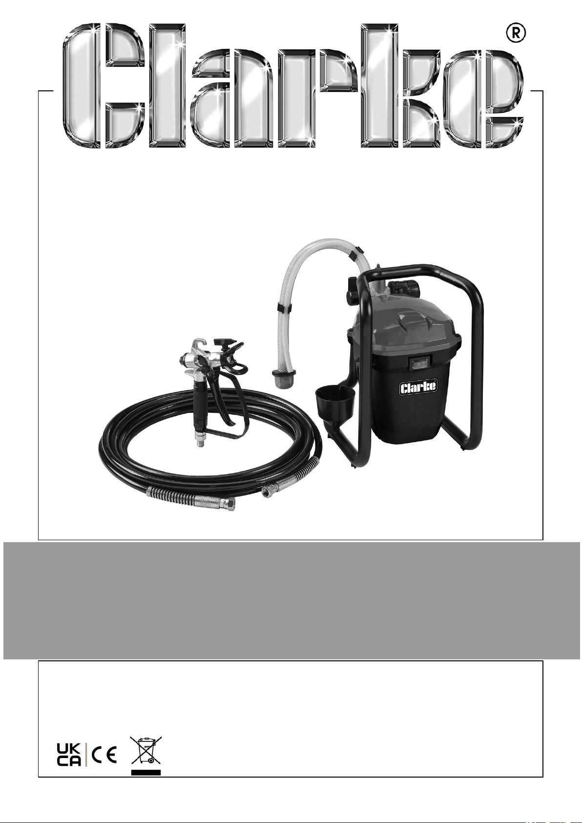
AIRLESS SPRAY GUN
MODEL NO: CAPS1
PART NO: 2310051
INSTRUCTIONS FOR USE
ORIGINAL INSTRUCTIONS GC06/25
Page 2
INTRODUCTION
Thank you for purchasing this CLARKE Airless Spray Gun. Airless spraying reduces the
mist associated with compressed air spraying and therefore reduces paint loss.
Your sprayer may be used with various spray mediums, including varnishes, wood
preservatives, masonry paints, enamel paints and oil and water based paints.
Before attempting to use this product, please read this manual thoroughly and follow
the instructions carefully. In doing so you will ensure the safety of yourself and that of
others around you, and you can look forward to your purchase giving you long and
satisfactory service.
SPECIFICATION
Weight 8.35 kg
Dimensions (L x H x W) 270 x 335 x 270mm
Paint hose length 7.6 m
Maximum working pressure 3000 Psi
Maximum nozzle flow rate 320 ml/min (water)
Rated input power 700 W
Rated current 2.0-4.5A
Rated current 2.0 - 4.5 A
Voltage 220-240 V / 50 Hz
Ingress protection IP23
Insulation Class Class I
Vibration emission value 0.715 m/s2 (uncertainty 1.5m/s2)
Sound pressure 97 db
GUARANTEE
This product is guaranteed against faulty manufacture for a period of 12 months from
the date of purchase. Please keep your receipt which will be required as proof of
purchase. This guarantee is invalid if the product is found to have been abused or
tampered with in any way, or not used for the purpose for which it was intended.
Faulty goods should be returned to their place of purchase, no product can be
returned to us without prior permission. This guarantee does not effect your statutory
rights.
2
Parts & Service: 020 8988 7400 / E-mail: [email protected] or [email protected]
Page 3

GENERAL SAFETY PRECAUTIONS
WORK AREA
1. Keep the work area clean and well lit. Cluttered and dark areas invite
accidents.
2. Keep children and bystanders away. Distractions can cause you to lose
control.
ELECTRICAL SAFETY
1. Power tools must match the power outlet. Never modify the plug in any
way. DO NOT use adaptor plugs with earthed (grounded) power tools.
Correct plugs and outlets will reduce the risk of electric shock.
2. DO NOT expose to rain or wet conditions. Any water will increase the risk of
electric shock.
3. DO NOT abuse the power cable. NEVER use the cable for pulling or
unplugging the power tool. Keep the cable away from sources of heat,
oil, sharp edges or moving parts. Damaged or tangled cables increase the risk
of electric shock.
PERSONAL SAFETY
1. Stay alert, watch what you are doing and use common sense when you
are operating a power tool. DO NOT operate a power tool when you are tired,
ill or under the influence of alcohol, drugs or medication.
2. Wear personal protective equipment including eye protection. Safety
equipment such as a dust mask, non-skid shoes or hearing protection used for
appropriate conditions will reduce personal injuries. Use a face or dust mask if
necessary. Wear ear protectors/defenders as the noise level of this machine can
exceed 85dB (A).
3. DO NOT over-reach. Keep your proper footing and balance at all times. This
enables better control of the power tool in unexpected situations.
4. Dress properly. Wear protective hair covering to contain long hair. For best
footing, wear rubber soled footwear. Keep floor clear of oil, scrap wood, etc.
5. Concentrate on the job in hand, no matter how trivial it may seem. Be aware that
accidents are caused by carelessness due to familiarity.
POWER TOOL USE AND CARE
1. DO NOT use the power tool if the switch does not turn it on and off. Any
power tool that cannot be controlled with the switch is dangerous and must be
repaired.
3
Parts & Service: 020 8988 7400 / E-mail: [email protected] or [email protected]
Page 4

2. Store power tools out of the reach of children and do not allow persons
unfamiliar with these instructions to operate the tool. Power tools are
potentially dangerous in the hands of untrained users.
3. Maintain power tools in top condition. Check for any condition that may
affect the power tool’s operation. Many accidents are caused by poorly maintained
power tools.
4. Use supplied accessories. The use of improper accessories could be hazardous.
5. Machine cleanliness. Clean the spray gun routinely as described under
Maintainence. DO NOT allow the ventilation slots in the housing to become
blocked with dust.
6. Check for damage before using the machine. Any damaged part should be
inspected to ensure that it will operate properly and perform its intended function.
Check for any condition that may affect the machine’s operation. Any damage
should be properly repaired or the part replaced. If in doubt, DO NOT use.
Consult your local dealer.
SERVICING
1. When necessary, have your power tools serviced or repaired by a
qualified person using identical replacement parts. This will ensure that
the safety of the power tool is maintained.
FURTHER PRECAUTIONS FOR PAINT SPRAYING
1. NEVER spray in the direction of persons or animals. NEVER spray paint against
the skin. In the case of injury, seek expert medical advice immediately.
2. ALWAYS make sure there is adequate ventilation. DO NOT spray in confined or
enclosed areas.
3. ALWAYS wear a suitable approved breathing mask when spraying, to protect
against inhalation of paint spray or fumes. An air feed mask may be required
when spraying some types of paint. If in doubt, check with the paint maker.
4. ALWAYS disconnect the spray gun from the electrical supply when it is not in use
and before cleaning or any disassembly.
5. ALWAYS keep the spray nozzle in place when spraying.
6. ALWAYS adhere to the paint manufacturers instructions when thinning paint.
7. ALWAYS disconnect from the mains supply when filling the paint container.
8. ALWAYS thoroughly clean the spray gun after use.
9. NEVER smoke while spraying or preparing paints, or spray near a naked flame or
heat source. Many paints are flammable.
10. NEVER use the spray gun outdoors when it is raining.
4
Parts & Service: 020 8988 7400 / E-mail: [email protected] or [email protected]
Page 5
ELECTRICAL CONNECTIONS
WARNING: READ THESE ELECTRICAL SAFETY INSTRUCTIONS
THOROUGHLY BEFORE CONNECTING THE PRODUCT TO THE
MAINS SUPPLY.
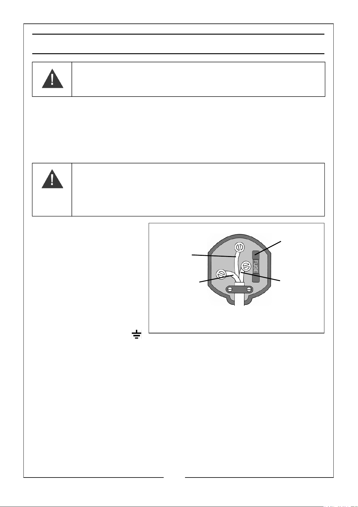
Connect the mains lead to a standard, 230 Volt (50Hz) electrical supply through an
approved 13 amp BS 1363 plug, or a suitably fused isolator switch.
If the plug has to be changed because it is not suitable for your socket, or because of
damage, it must be removed and a replacement fitted, following the wiring
instructions shown below. The old plug must be discarded safely, as insertion into a
power socket could cause an electrical hazard.
WARNING: THE WIRES IN THE POWER CABLE OF THIS
PRODUCT ARE COLOURED IN ACCORDANCE WITH THE
FOLLOWING CODE:
BLUE = NEUTRAL BROWN = LIVE YELLOW AND GREEN =
EARTH
• The BLUE wire must be
connected to the
terminal marked N or
coloured black.
• The BROWN wire must
be connected to the
terminal marked L or
coloured red.
• The YELLOW AND
GREEN wire must be
connected to the
terminal marked E or
or coloured green.
We strongly recommend that this machine is connected to the mains
supply through a Residual Current Device (RCD).
If you are not sure, consult a qualified electrician. DO NOT try to do any repairs.
(Green and
Yellow)
Plug must be BS1363/A approved.
Earth
Neutral
(Blue)
Ensure that the outer sheath of
the cable is firmly held by the clamp
Always fit
a 13 Amp
fuse.
Live
(Brown)
5
Parts & Service: 020 8988 7400 / E-mail: [email protected] or [email protected]
Page 6
OVERVIEW
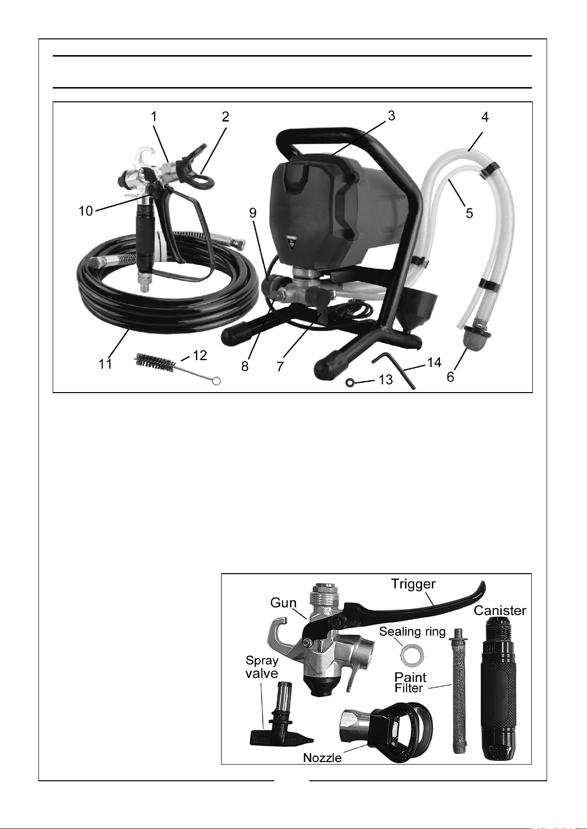
1 Spray gun assembly 8 Pressure relief valve
2 Nozzle 9 Pressure Control Knob
3 Power switch 10 Trigger Lock
4 Suction tube 11 Spray hose
5 Priming tube 12 Cleaning brush
6 Suction Filter 13 Spare O-ring
7 Prime/Spray Switch 14 Allen Key
GUN ASSEMBLY
1. Spray gun
2. Prime/Spray valve
3. Sealing O-ring
4. Nozzle assembly
5. Paint filter
6. Canister
7. Trigger
6
Parts & Service: 020 8988 7400 / E-mail: [email protected] or [email protected]
Page 7
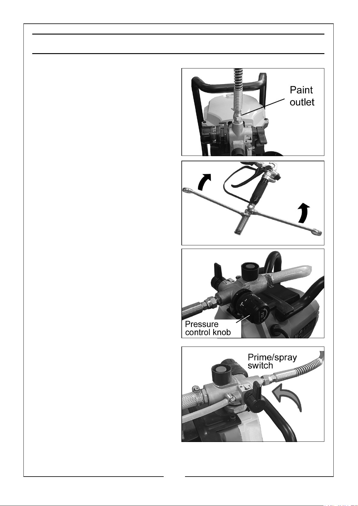
ASSEMBLY
1. Attach the paint hose to the outlet
and tighten with a 19mm wrench.
2. Attach the paint hose to the paint
gun and tighten with two 19mm
wrenches.
3. Turn the pressure control knob to the
Low Pressure setting.
RELIEVING SPRAY PRESSURE
1. Turn the power switch off and unplug
machine from the power outlet.
2. Switch the Prime/Spray switch to the
Prime mode.
3. Point the gun into a bucket and
squeeze the trigger to relieve
pressure.
4. Turn the trigger lock knob to the
Locking position.
NOTE: Always set to Prime mode between uses.
7
Parts & Service: 020 8988 7400 / E-mail: [email protected] or [email protected]
Page 8
BEFORE STARTING
1. Check all fittings and connections making sure that they are tight.
2. When newly delivered, flush any protective oil from the machine with hot, soapy
water before spraying.
START-UP
1. Remove the spray tip from the gun
2. Put the inlet hose and pressure relief
tube into a bucket with some water
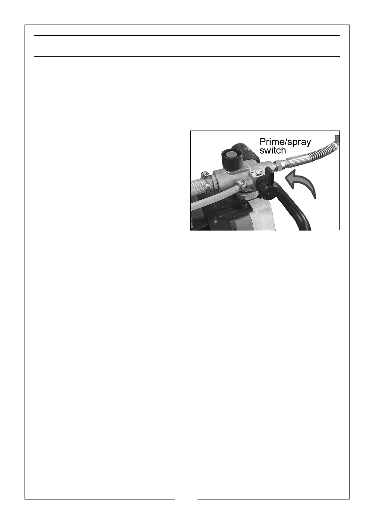
3. Switch on the motor and push the
Prime/Spray Switch upright. In a few
seconds water will begin to flow up
through the tube and flow from the
outlet valve. Tighten the outlet valve
clockwise then tighten the pressure
valve clockwise.
4. When full pressure is reached, check if there is any leakage on the outlet hose. If
all OK, open the spray gun for a test spray. Change any soapy water and use clean
water for the spray to run clean.
5. Turn off the power and continue spraying until no more water comes out.
6. Unlock the trigger lock. Set the Prime/Spray Switch upright until there is no soapy
water in the pump.
PRESSURE RELEASE PROCEDURE
Whenever instructed to relieve pressure, stop spraying and check or install a clean
spray tip.
Engage the trigger safety lock on the gun. Turn off the power and turn the sprayer
pressure control to the lowest pressure setting.
Hold the gun in a bucket and discharge any remaining pressure into the bucket.
PRIMING THE SPRAY GUN
OIL-BASED PAINT
Flush with mineral spirits followed by warm, clear water.
WATER-BASED PAINT
Flush with warm, clean water.
8
Parts & Service: 020 8988 7400 / E-mail: [email protected] or [email protected]
Page 9
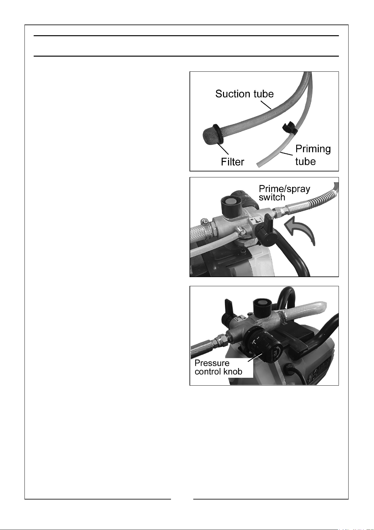
PRIMING AND STARTUP PROCEDURE
1. Separate the smaller priming tube
from the suction tube.
2. Place the priming tube in the waste
bucket.
3. Submerge the suction tube in water
or flushing solvent.
4. Turn the Prime/Spray switch to the
Prime mode.
5. Adjust the pressure control knob to
the prime/clean setting.
6. Plug in the sprayer and turn on the
power.
• The sprayer will start pumping and
water or flushing solvent as well
as air bubbles will be purged from
the system.
7. Let the fluid discharge from the
priming tube into the waste container
for 30 to 60 seconds before switching off the power.
8. Remove the suction tube from the water or flushing solvent and immerse in the
paint container.
9. Switch on the power.
• The paint should now pass from the suction tube to the sprayer and the
priming tube until discharging from the return tube.
9
Parts & Service: 020 8988 7400 / E-mail: [email protected] or [email protected]
Page 10
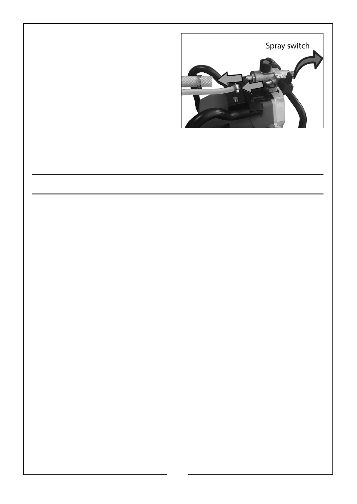
10. Turn the Prime/Spray switch to Spray
mode and continue spraying away
any waste.
11. Stop spraying and engage the trigger
lock.
12. Remove the priming tube from the
waste bucket before clipping to the
suction tube and submerging in the
paint container.
13. If the motor stops, the pump and
tubes are primed. If it does not stop repeat the priming steps.
14. Start painting.
SURFACE PREPARATION
To obtain the best results it is important that you prepare the surface to be sprayed
and thin the paint to the correct viscosity before spraying.
Always ensure that surfaces to be sprayed are free from dust, dirt and grease. Make
sure that you have masked the areas that should not be sprayed, using a good quality
masking tape.
The paint or fluid to be sprayed should be thoroughly mixed and free from lumps or
other particles. Many substances can be sprayed with your spray gun but always
check the manufacturer’s recommendations before purchasing your paint. DO NOT
use textured wall paints or coatings as this will block the nozzle.
THINNING
Most paints are supplied ready for brush application and will need to be thinned
before they are suitable to be sprayed.
Follow the manufacturer's advice on thinning
If the paint takes longer than the recommended time to empty then further thinning
is required. Mix in a small quantity of the appropriate thinner until the correct
consistency is achieved. Some sprayable materials contain particles and lumps. These
materials should be strained before filling the paint container.
10
Parts & Service: 020 8988 7400 / E-mail: [email protected] or [email protected]
Page 11
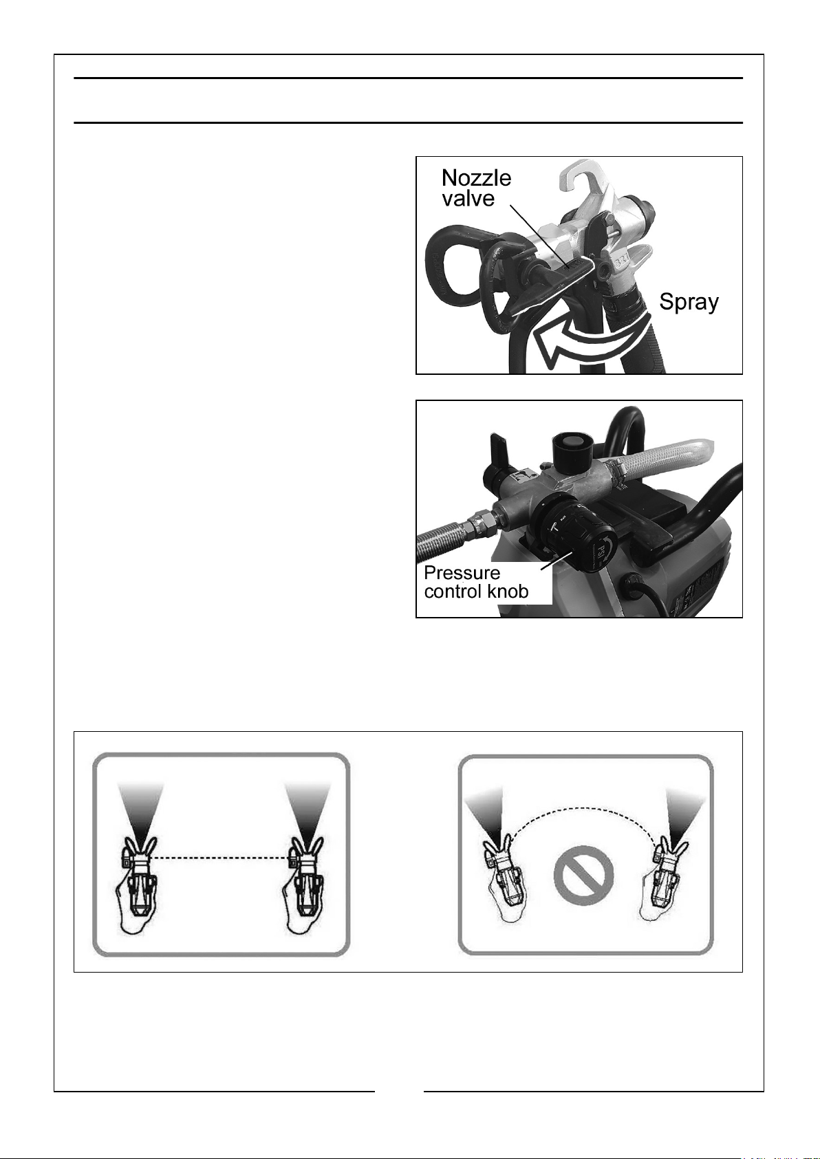
OPERATING THE SPRAY GUN
1. Fill the paint container with the
correctly thinned and strained paint
and connect the spray gun to the
power supply.
2. Ensue the sprayer has been primed
and confirm the nozzle is aligned
correctly.
3. Remove or cover areas and items to
be protected from overspray or paint
mist.
4. Once primed, adjust the nozzle valve
to the Spray setting
5. Start spraying at the lowest setting
on the Pressure Control knob and
increase pressure as needed by
turning clockwise to create a good
spray patten.
SPRAYING TECHNIQUES
Aim the spray gun at a piece of scrap
material and operate the trigger until paint is spraying.
Adjustment of the output control will affect the pattern. A poor spray pattern will
concentrate the paint in the centre of the spray and give a blotchy finish. A good
spray pattern will give even distribution of paint throughout the pattern.
To obtain the best results, keep your spray gun level and parallel to the surface at all
times. Keep the nozzle 25 - 30 cm from the surface and spray evenly from side to side
or up and down. DO NOT spray at an angle as this will lead to paint runs on the
surface. Use smooth and even strokes.
11
Parts & Service: 020 8988 7400 / E-mail: [email protected] or [email protected]
Page 12
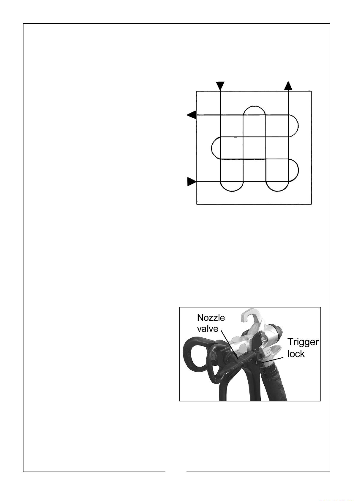
Overlap strokes by half and always aim each stroke at the bottom
edge of the last stroke.
When spraying large areas, using a criss-cross pattern as shown.
Never start or stop the spray gun while it
is aimed at the surface to be sprayed.
Evenly control the speed of movement of
the spray gun.
• Moving quickly over the surface
will give a thin coat and slow
movement will give a heavy coat.
• Apply one coat at a time. If a
further coat is required, make sure
you observe the manufacturers
drying time recommendations
before applying a second coat.
• When spraying small areas, keep
the output control on a low
setting. This will avoid using too much paint and prevent over-spray.
• Where possible, avoid stopping and starting when spraying an object. This
can lead to too much, or not enough paint being applied. Do not tip the
spray gun to more than 45o.
CLEARING THE SPRAY TIP
Occasionally the spray gun tip will become clogged with paint and the following
instructions should be followed.
1. Switch off and set the trigger lock.
2. Adjust the nozzle valve to the Clean
setting.
12
Parts & Service: 020 8988 7400 / E-mail: [email protected] or [email protected]
Page 13
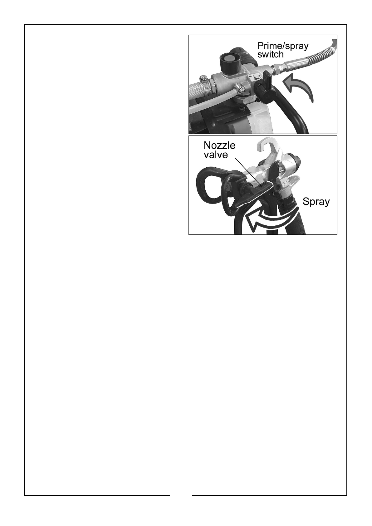
3. Turn the Prime/Spray switch to Spray
mode.
4. Turn the power back on.
5. Unlock the trigger.
6. Spray into the waste container until
the clog clears.
7. Release the trigger and engage the
trigger lock.
8. Adjust the nozzle valve to Spray
mode.
13
Parts & Service: 020 8988 7400 / E-mail: [email protected] or [email protected]
Page 14
CLEANING AND MAINTENANCE
ROUTINE CLEANING
CAUTION: ALWAYS REMEMBER TO DISCONNECT FROM THE MAINS SUPPLY
BEFORE CLEANING THE SPRAY GUN.
Continuous satisfactory operation depends upon proper care and regular cleaning. It
is essential that the spray gun is cleaned thoroughly after every use. Failure to clean it
will almost certainly result in blockages and it may not operate when you next come
to use it! The guarantee does not cover cleaning a sprayer that has not been properly
cleaned by the user. The following action must be taken after every use:
• For oil based paint, flush with mineral (white) spirit followed by warm clean
water.
• For water-based paints, flush with warm clean water.
1. Relieve pressure and drain all paint from the tubes.
2. Separate the tubes.
3. Place the priming (small) tube in an empty waste container.
4. Submerge the suction (large) tube in water or flushing liquid.
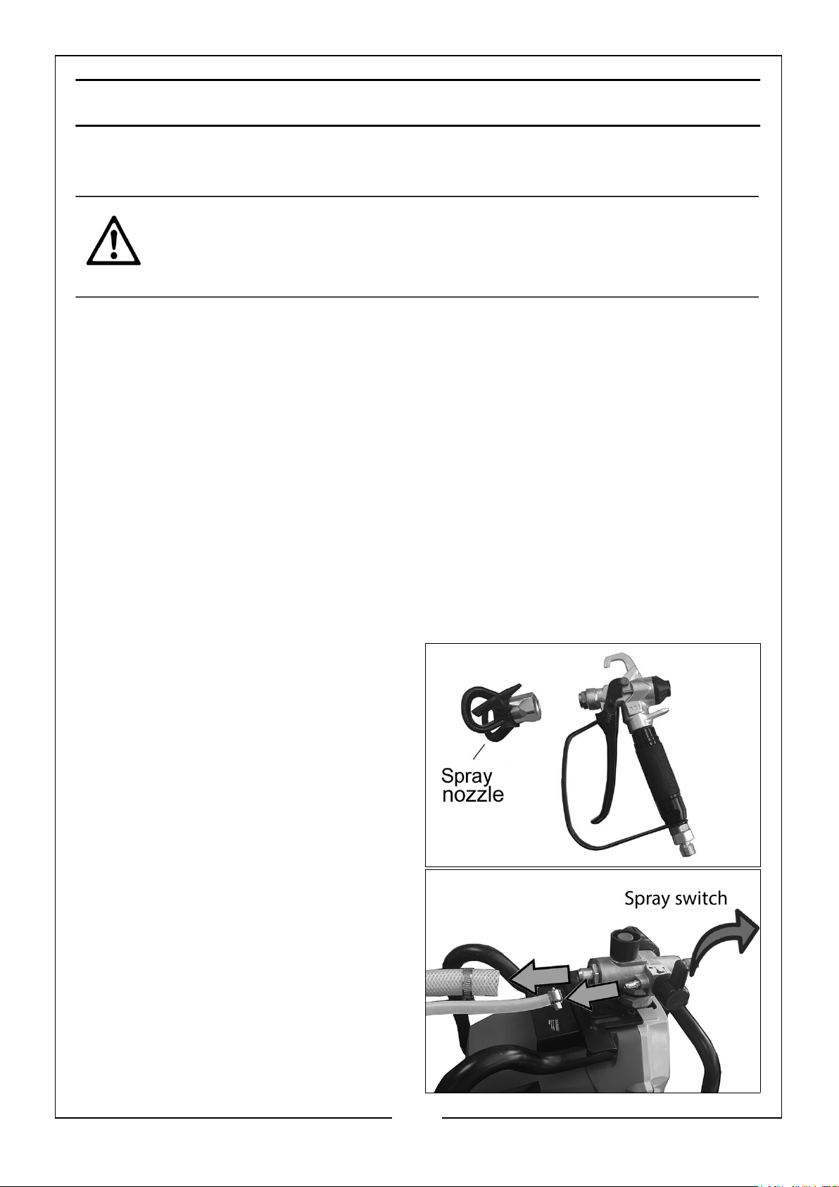
5. Un-screw the spray nozzle and
remove from the gun assembly.
6. Turn the spray switch to Spray mode.
7. Switch the power on.
8. Spray the paint into the paint
container
9. Change to the waste container as the
paint thins.
14
Parts & Service: 020 8988 7400 / E-mail: [email protected] or [email protected]
Page 15
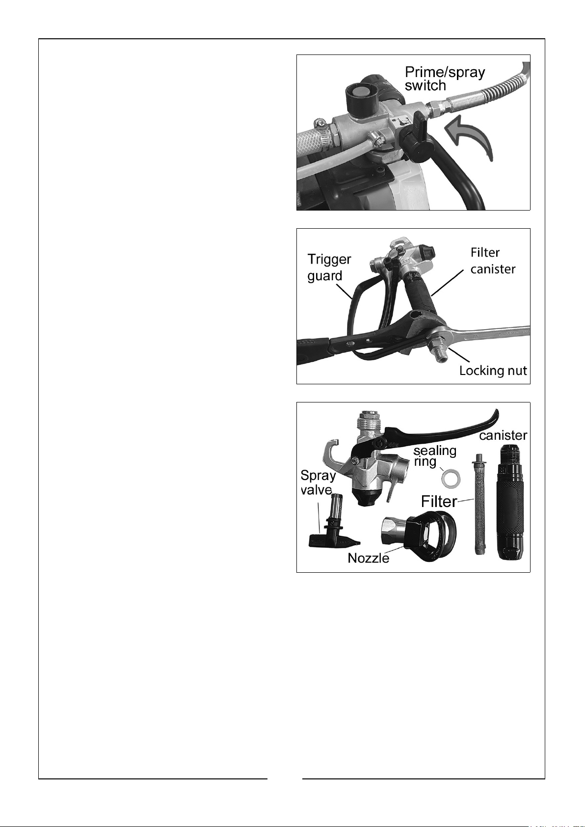
10. Turn the spray switch to Prime mode.
11. Continue to flush until clear
12. Release the trigger. Turn off and
relieve pressure.
13. Remove the trigger guard from the
housing using a 19 mm wrench by
unscrewing the nut shown.
14. Unscrew the filter canister to access
the filter and pull the filter from the
gun assembly.
15. Clean all spray gun parts in warm,
soapy water or flushing liquid with a
bristle brush.
15
Parts & Service: 020 8988 7400 / E-mail: [email protected] or [email protected]
Page 16
LONG TERM CARE
LONG TERM MAINTENANCE
Please be aware that certain parts of this spray gun may wear with long term use,
requiring replacement. These include the valves, spray nozzle, piston and spring. The
wear on these parts depends on the abrasiveness of the materials being sprayed.
More abrasive materials, such as emulsions, will cause these parts to wear much
faster.
Worn valves and nozzles will have larger holes and scratches on the internal surfaces.
This is likely to cause a poor spray pattern and will eventually require replacing.
Replacement valves are available from your dealer or the Clarke International Parts
Department.
LONG TERM STORAGE
When cleaning for long term storage it is important that the paint sprayer is not left
with any water or water-based material still in the pump, hose or tubes, or the spray
gun as this can corrode the machine.
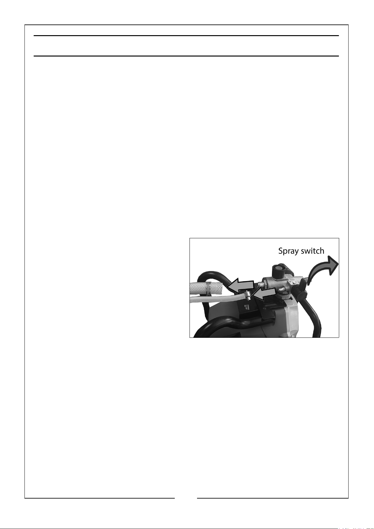
1. Remove the paint hose if not already
removed.
2. Loosen the clamps from both the
tubes and disconnect them from the
pump.
3. Add an ounce of light household oil
or a pump storage product into each
inlet.
4. Turn the Prime/Spray switch to
Spray.
5. Turn the pressure control knob to Low Spray.
6. Hold a rag over the paint hose outlet.
7. Switch the power to On for five seconds then turn Off.
8. Turn the prime/spray switch to Prime. This will keep storage fluids in the sprayer.
9. Replace the tubes and secure with the clamps.
10. Wipe the sprayer with a clean cloth and store in a dry location out of reach of
children.
16
Parts & Service: 020 8988 7400 / E-mail: [email protected] or [email protected]
Page 17
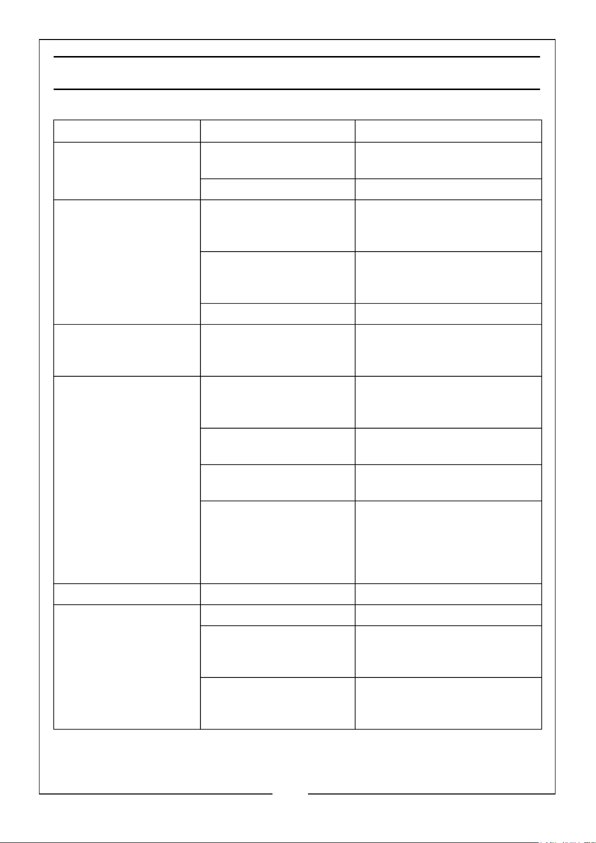
FAULTFINDING
Problem
Atomization is poor Volume adjustment not
Over painting Gun not clean or not
Motor louder than
normal
Failure to operate normally
Cause Solution
correct
Paint too thick Check viscosity of paint
lubricated, resulting in
piston sticking in cylinder
Too much paint Adjust the volume clockwise to
Paint too thin Check viscosity
Gun not clean or not
lubricated causing piston
to stick in cylinder.
Motor will not run if
pressure control knob set
at a minimum
Adjust the output control
Dismantle the spray gun and
clean with thinner.
reduce spraying. Apply two thin
coats of paint.
Dismantle the spray gun and
clean with thinner.
Slowly increase pressure setting
to see if motor starts
Spray tip or fluid filter
may be clogged
Blockage of hardened
paint
Displacement pump
connecting rod pin not
correctly fitted
No spray or sound No electrical power Check power supply.
Operating sound not
normal
Poor output adjustment Re-adjust output control
Not enough paint in
container resulting in air
being sucked in.
Paint not properly diluted
or not passing pick-up
completely.
Relieve pressure then clear or
clean the gun filter.
Clean out and replace pump
packings
Push pin into place and secure
with spring retainer. Check that
pin is pushed into connecting
rod and spring is firmly in the
groove
Re-fill with paint.
Check cleanliness of pick-up
pipe and viscosity of paint.
17
Parts & Service: 020 8988 7400 / E-mail: [email protected] or [email protected]
Page 18
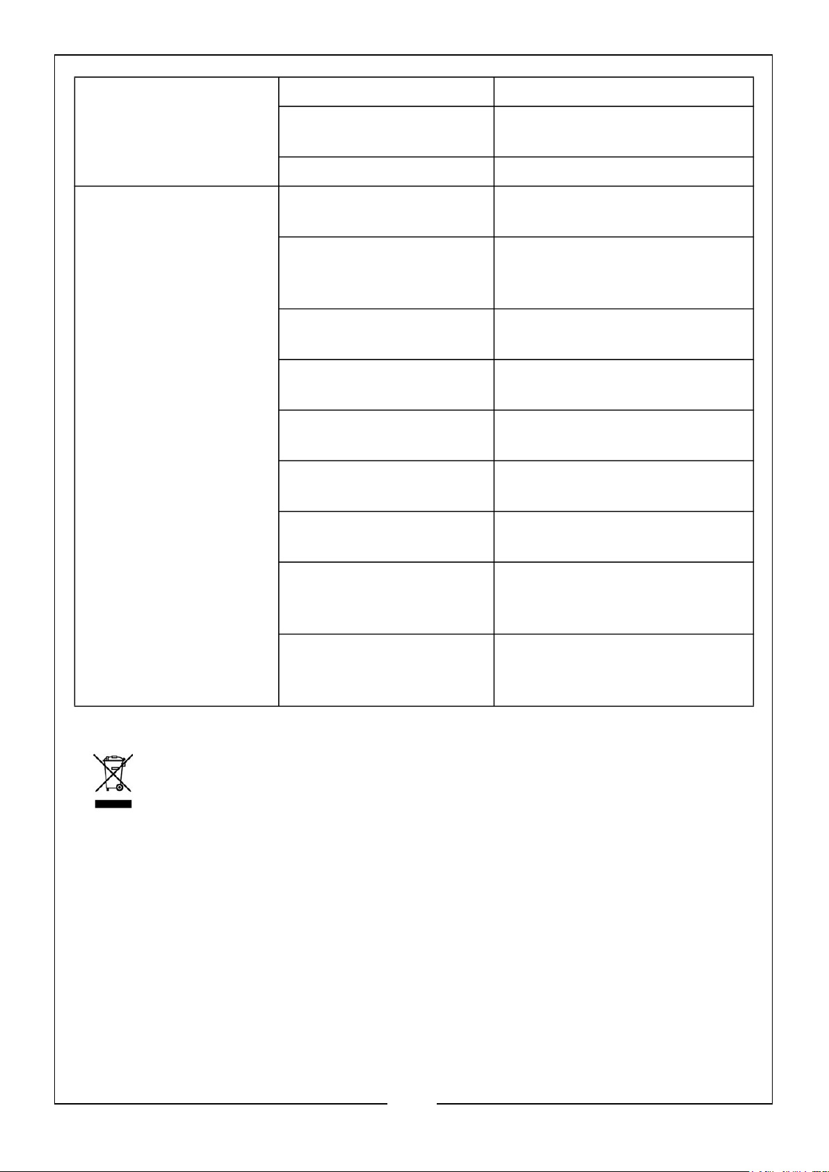
Orange peel or excessive
fogging.
Incorrect solvent used. Use different solvent.
Spray gun too far from
work surface.
Hold spray gun closer to the
work surface.
Paint too thick. Thin the paint.
Low output
Worn spray nozzle. Relieve pressure and replace
nozzle.
Verify pump does not
Service pump.
continue to stroke when
gun trigger is released.
Prime valve leaking. Relieve pressure then repair
prime valve.
Poor suction tube
connections.
Extension cable
Tighten any loose connections.
Check O-ring on suction tube.
Replace with shorter cable.
excessively long.
Loose or defective internal
wiring.
Have technician examine for
defects.
Worn motor brushes. Check motor brushes are 6mm
and replace if necessary.
Motor brushes binding in
brush holders.
Clean debris and dust from
brush holders using compressed
air to blow out dust.
Low stall pressure. Turn pressure control knob fully
clockwise. Replace pressure
control assembly.
ENVIRONMENTAL PROTECTION
If disposing of this product or any damaged component, do not dispose of it
with general waste. This product contains valuable raw materials which
should be taken to your local civic amenity site for recycling.
Through purchase of this product, the customer is taking on the obligation to deal
with the WEEE in accordance with the WEEE regulations in relation to the treatment,
recycling & recovery and environmentally sound disposal of the WEEE.
In effect, this means that this product must not be disposed of with general
household waste. It must be disposed of according to the laws governing Waste
Electrical and Electronic Equipment (WEEE) at a recognised disposal facility.
18
Parts & Service: 020 8988 7400 / E-mail: [email protected] or [email protected]
Page 19
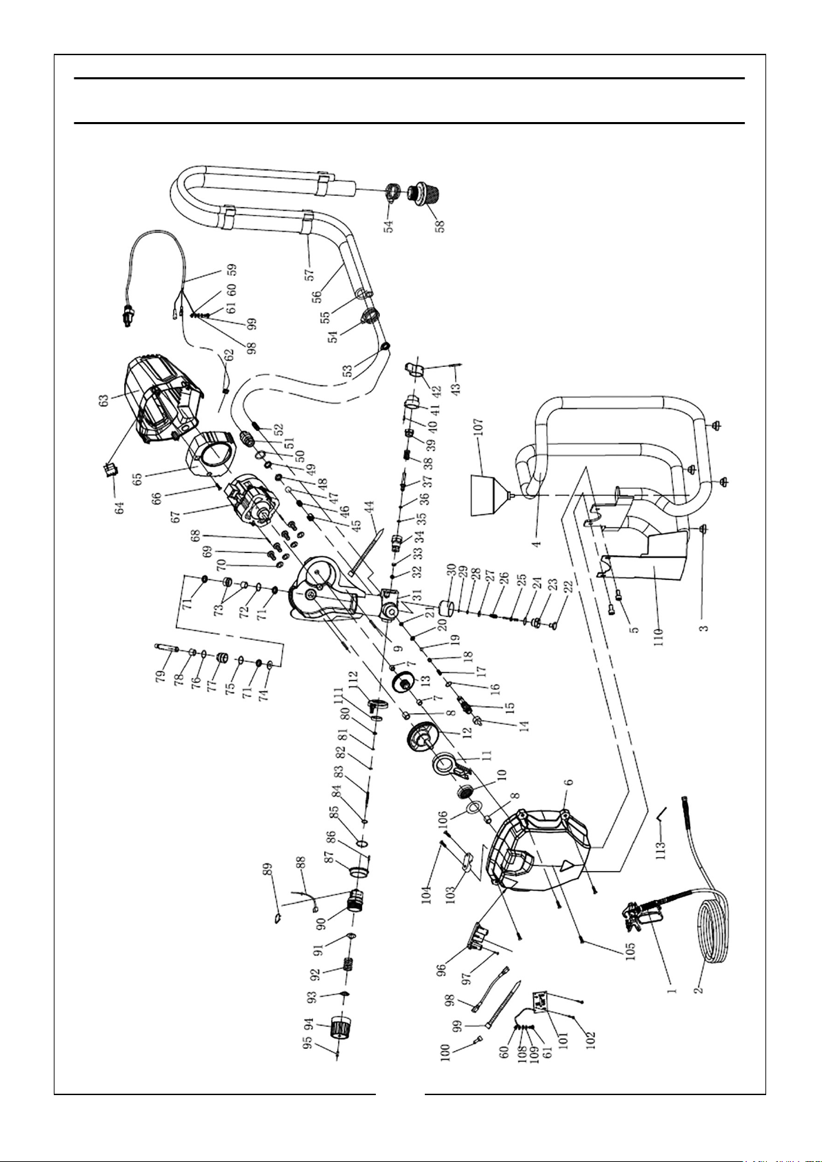
Page 20
COMPONENT PARTS
NO
1 Airless spray gun assembly 31 Pump housing
2 Paint hose 32 Plastic washer
3 Foot pad 33 Pressure relief valve pad
4. Base frame 34 Pressure relief valve seat
5 Hex bolt M6 x 25 35 O-ring 5 x 1.8
6 Pump cover 36 Ring
7 Small copper sleeve 37 Pressure relief valve rod
8 Large copper sleeve 38 Spring
9 Pin 5x12 39 Spring seat
10 Roller bearing 40 Pin 3x8
11 Connecting rod 41 Switch seat
12 Output gear 42 Switch lever
13 Screw 43 Pin
DESCRIPTION NO DESCRIPTION
14 Screw threaded insert 44 Nylon cable tie
15 Paint outlet 45 Inlet spring holder
16 O-ring 10 x1.8 46 Inlet spring
17 Output spring 47 Steel ball 12.7
18 Pole 48 Inlet valve seat
19 Steel ball 6.4 49 Inlet valve seat washer
20 Seal seat 50 O-ring 17 x 1.8
21 Output washer 51 Paint inlet adapter
22 Touch handle 52 Pressure relief plug
23 Touch seat 53 Small hose clamp
24 O-ring 10 x 1.5 54 Large hose clamp
25 Touch rod 55 Priming tube
26 Touch spring 56 Suction tube
27 Copper washer 57 Clip
28 Ring 58 Filter assembly
29 O-ring 2.4 x 1.8 59 Power plug
30 Cover 60 Locking ring
20
Parts & Service: 020 8988 7400 / E-mail: [email protected] or [email protected]
Page 21
NO
DESCRIPTION NO DESCRIPTION
61 Screw 88 Micro switch assembly
62 Cable clamp 89 Micro switch cover
63 Housing 90 Adjusting seat
64 Power switch 91 Deflating cap
65 Shutter exhaust cover 92 Pressure adjusting spring
66 Bolt 93 Spring pusher
67 Motor assembly 94 Adjusting sleeve insert
68 Pin 3 x 12 95 Pressure control bolt
69 Hex bolt M5 x 14 96 PCB support
70 Spring washer 97 Screw
71 Circlip 98 Wire connector
72 O-ring 22.5 x 1.8 99 Nylon cable tie
73 Joint stopper 100 Cap
74 Piston washer 101 PCB assembly
75 Tabletting 102 Self tapping screw
76 O-ring 26.5 x 1.8 103 Power cable clamp
77 Plunger seat 104 Screw
78 Guide sheath 105 Hex bolt
79 Plunger rod 106 Collar
80 Locking sleeve 107 Cup
81 Reinforcing seal 108 Flat washer
82 White sealing washer 109 Spring washer
83 Switch pole 110 Breakwater
84 O-ring 8.8 x 1.9 111 Label
85 O-ring 27 x 2.4 112 Sticker
86 Hex bolt 113 4mm wrench
87 Cap
21
Parts & Service: 020 8988 7400 / E-mail: [email protected] or [email protected]
Page 22
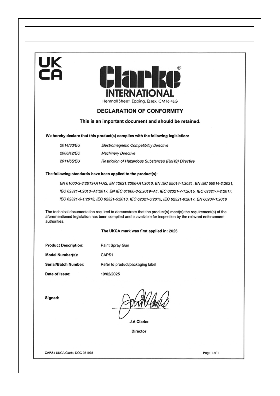
DECLARATION OF CONFORMITY - UK
22
Parts & Service: 020 8988 7400 / E-mail: [email protected] or [email protected]
Page 23
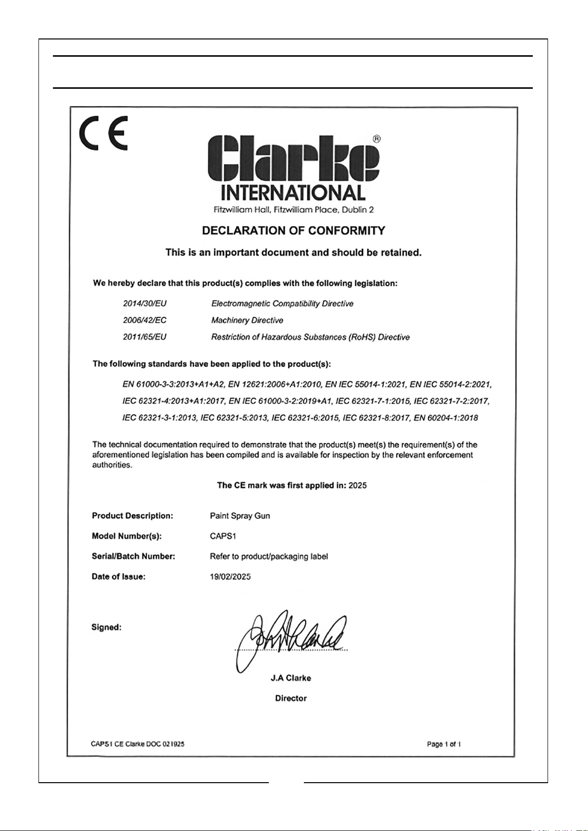
DECLARATION OF CONFORMITY-EU
23
Parts & Service: 020 8988 7400 / E-mail: [email protected] or [email protected]
Page 24

 Loading...