

Page 1
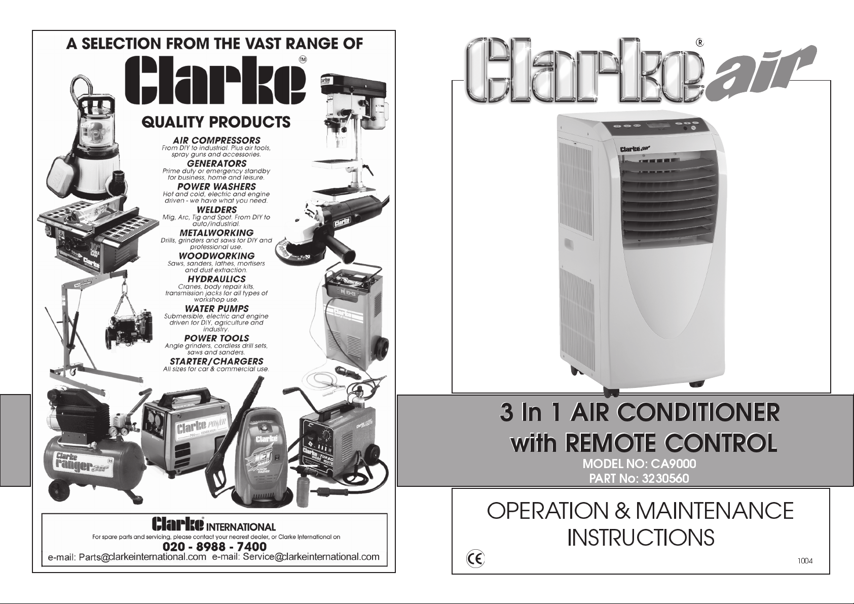
3 In 1 AIR CONDITIONER
3 In 1 AIR CONDITIONER
with REMOTE CONTROL
with REMOTE CONTROL
MODEL NO: CA9000
PART No: 3230560
OPERATION & MAINTENANCE
INSTRUCTIONS
1004
Page 2
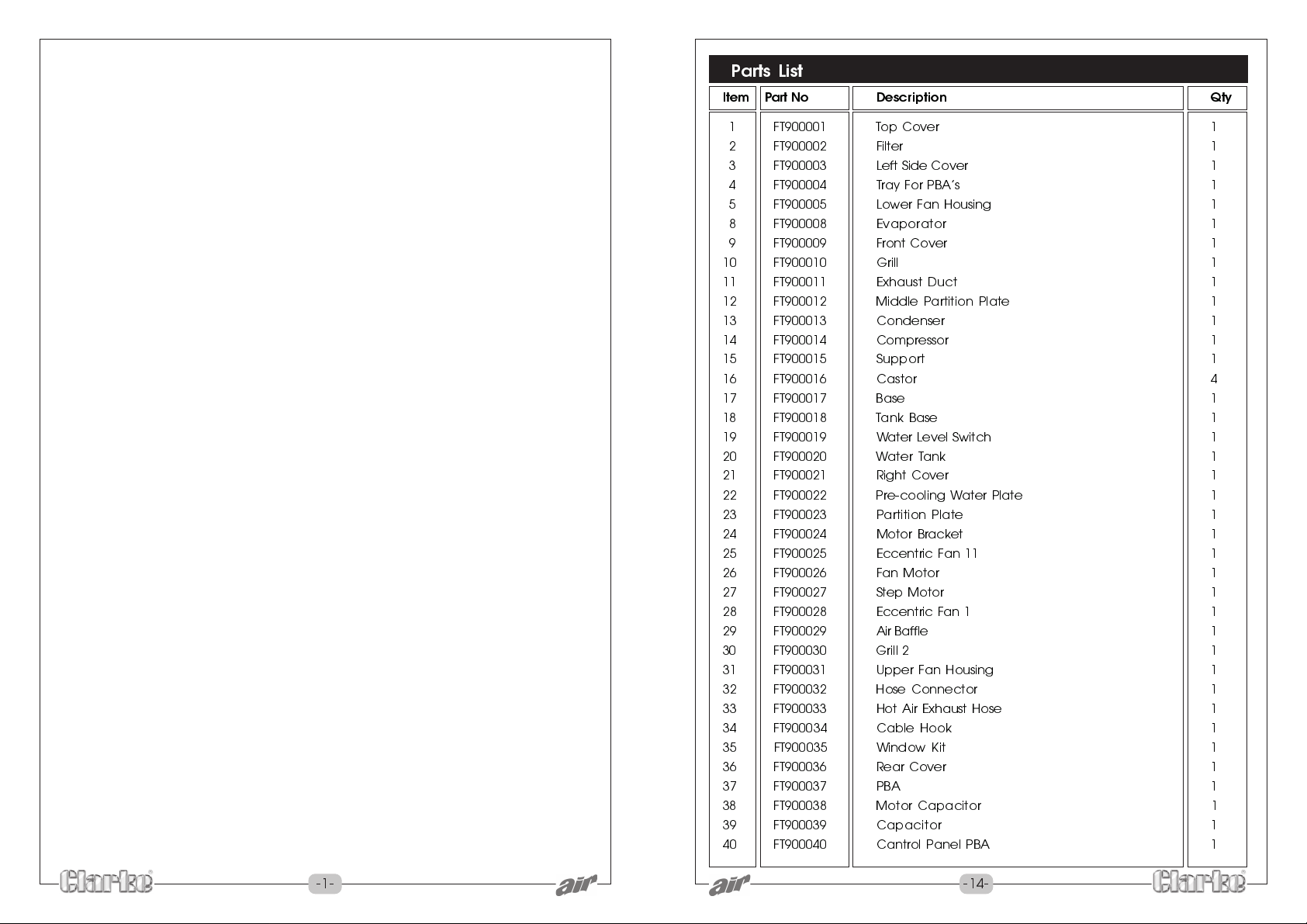
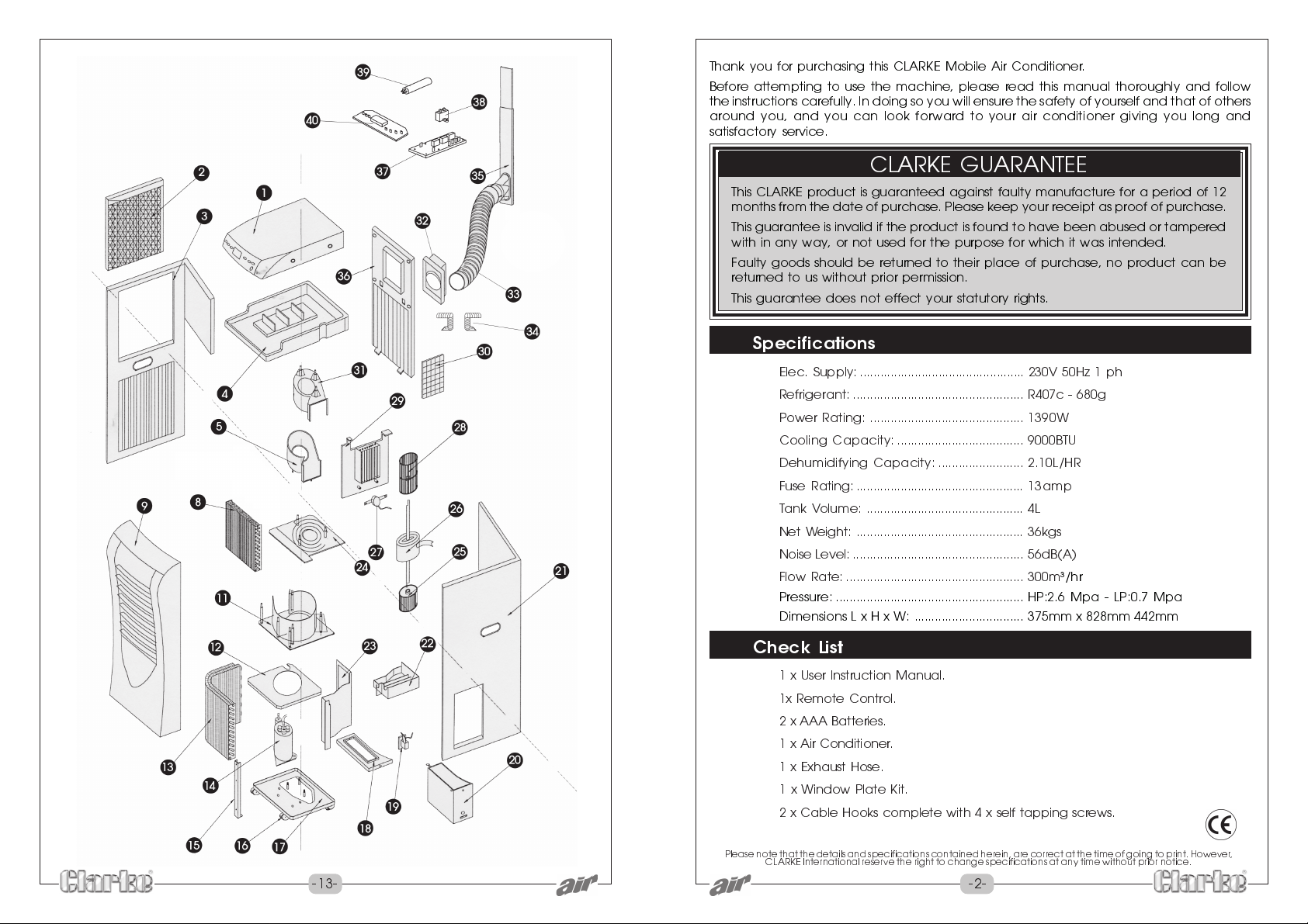
Parts List
Item Part No Description Qty
1 FT900001 Top Cover 1
2 FT900002 Filter 1
3 FT900003 Left Side Cover 1
4 FT900004 Tray For PBAs 1
5 FT900005 Lower Fan Housing 1
8 FT900008 Evaporator 1
9 FT900009 Front Cover 1
10 FT900010 Grill 1
11 FT900011 Exhaust Duct 1
12 FT900012 Middle Partition Plate 1
13 FT900013 Condenser 1
14 FT900014 Compressor 1
15 FT900015 Support 1
16 FT900016 Castor 4
17 FT900017 Base 1
18 FT900018 Tank Base 1
19 FT900019 Water Level Switch 1
20 FT900020 Water Tank 1
21 FT900021 Right Cover 1
22 FT900022 Pre-cooling Water Plate 1
23 FT900023 Partition Plate 1
24 FT900024 Motor Bracket 1
25 FT900025 Eccentric Fan 11 1
26 FT900026 Fan Motor 1
27 FT900027 Step Motor 1
28 FT900028 Eccentric Fan 1 1
29 FT900029 Air Baffle 1
30 FT900030 Grill 2 1
31 FT900031 Upper Fan Housing 1
32 FT900032 Hose Connector 1
33 FT900033 Hot Air Exhaust Hose 1
34 FT900034 Cable Hook 1
35 FT900035 Window Kit 1
36 FT900036 Rear Cover 1
37 FT900037 PBA 1
38 FT900038 Motor Capacitor 1
39 FT900039 Capacitor 1
40 FT900040 Cantrol Panel PBA 1
-1- -14-
Page 3
Thank you for purchasing this CLARKE Mobile Air Conditioner.
Before attempting to use the machine, please read this manual thoroughly and follow
the instructions carefully. In doing so you will ensure the safety of yourself and that of others
around you, and you can look forward to your air conditioner giving you long and
satisfactory service.
CLARKE GUARANTEE
This CLARKE product is guaranteed against faulty manufacture for a period of 12
months from the date of purchase. Please keep your receipt as proof of purchase.
This guarantee is invalid if the product is found to have been abused or tampered
with in any way, or not used for the purpose for which it was intended.
Faulty goods should be returned to their place of purchase, no product can be
returned to us without prior permission.
This guarantee does not effect your statutory rights.
Specifications
Elec. Supply: ................................................ 230V 50Hz 1 ph
Refrigerant: .................................................. R407c - 680g
Power Rating: ............................................. 1390W
Cooling Capacity: ..................................... 9000BTU
Dehumidifying Capacity: ......................... 2.10L/HR
Fuse Rating: ................................................. 13amp
Tank Volume: .............................................. 4L
Net Weight: ................................................. 36kgs
Noise Level: .................................................. 56dB(A)
Flow Rate: .................................................... 300m³/hr
Pressure: ....................................................... HP:2.6 Mpa - LP:0.7 Mpa
Dimensions L x H x W: ................................ 375mm x 828mm 442mm
Check List
1 x User Instruction Manual.
1x Remote Control.
2 x AAA Batteries.
1 x Air Conditioner.
1 x Exhaust Hose.
1 x Window Plate Kit.
2 x Cable Hooks complete with 4 x self tapping screws.
Please note that the details and specifications contained herein, are correct at the time of going to print. However,
CLARKE International reserve the right to change specifications at any time without prior notice.
-13- -2-
Page 4
Electrical Connections
This product is provided with a standard 13 amp, 230 volt (50Hz), BS 1363 plug, for
connection to a standard, domestic electrical supply. Should the plug need changing
at any time, ensure that a plug of identical specification is used.
WARNING ! THIS APPLIANCE MUST BE EARTHED
This machine must be wired up in accordance with the following colour code:
BLUE - NEUTRAL
BROWN - LIV E
GREEN/YELLOW - EARTH
Connect the BLUE coloured cord to the plug terminal marked N
Connect the BROWN coloured cord to the plug terminal marked L
Connect the GREEN/YELLOW coloured cord to the plug terminal marked E
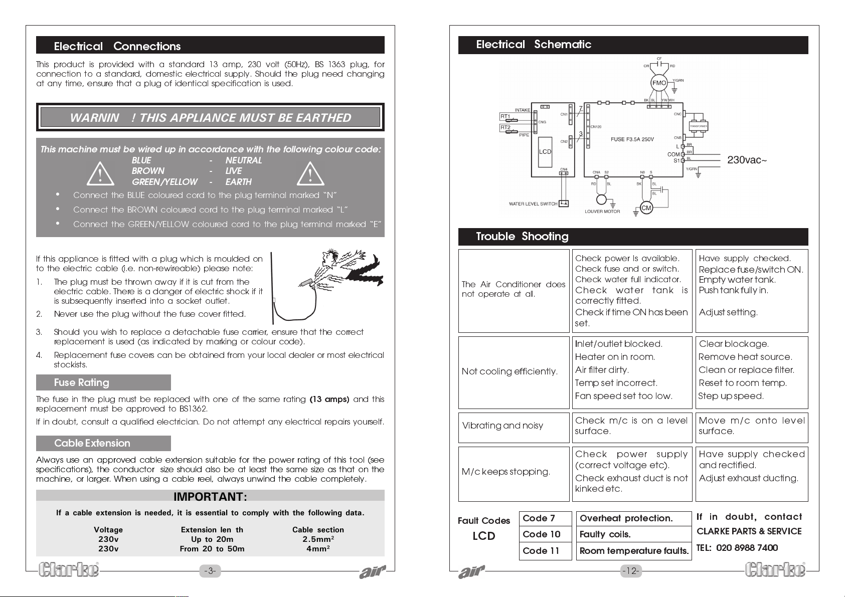
Electrical Schematic
Trouble Shooting
If this appliance is fitted with a plug which is moulded on
to the electric cable (i.e. non-rewireable) please note:
1. The plug must be thrown away if it is cut from the
electric cable. There is a danger of electric shock if it
is subsequently inserted into a socket outlet.
2. Never use the plug without the fuse cover fitted.
3. Should you wish to replace a detachable fuse carrier, ensure that the correct
replacement is used (as indicated by marking or colour code).
4. Replacement fuse covers can be obtained from your local dealer or most electrical
stockists.
Fuse Rating
The fuse in the plug must be replaced with one of the same rating
replacement must be approved to BS1362.
If in doubt, consult a qualified electrician. Do not attempt any electrical repairs yourself.
(13 amps)
and this
Cable Extension
Always use an approved cable extension suitable for the power rating of this tool (see
specifications), the conductor size should also be at least the same size as that on the
machine, or larger. When using a cable reel, always unwind the cable completely.
IMPORTANT:
If a cable extension is needed, it is essential to comply with the following data.
Voltage Extension length Cable section
230v Up to 20m 2.5mm
230v From 20 to 50m 4mm
2
2
The Air Conditioner does
not operate at all.
Not cooling efficiently.
Vibrating and noisy
M/c keeps stopping.
Fault Codes
LCD
Code 7 Overheat protection.
Code 10
Code 11 Room temperature faults.
Check power Is available. Have supply checked.
Check fuse and or switch.
Check water full indicator.
Check water tank is
Replace fuse/switch ON.
Empty water tank.
Push tank fully in.
correctly fitted.
Check if time ON has been
Adjust setting.
set.
Inlet/outlet blocked. Clear blockage.
Heater on in room. Remove heat source.
Air filter dirty. Clean or r eplace filter.
Temp set incorrect. Reset to room temp.
Fan speed set too low. Step up speed.
Check m/c is on a level
surface.
Check power supply
(correct voltage etc).
Check exhaust duct is not
Move m/c onto level
surface.
Have supply checked
and rectified.
Adjust exhaust ducting.
kinked etc.
If in doubt, contact
Faulty coils.
CLARKE PARTS & SERVICE
TEL: 020 8988 7400
-3- -12-
Page 5
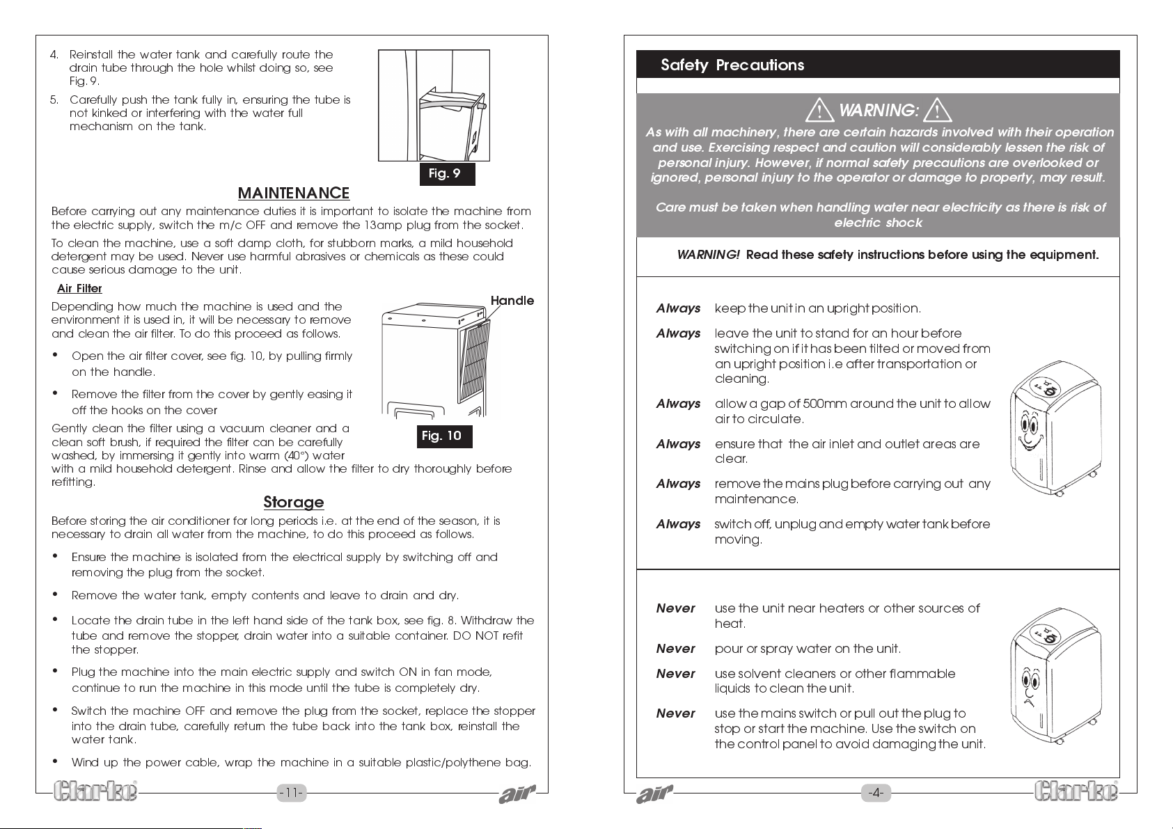
4. Reinstall the water tank and carefully route the
drain tube through the hole whilst doing so, see
Fig. 9.
5. Carefully push the tank fully in, ensuring the tube is
not kinked or interfering with the water full
mechanism on the tank.
Fig. 9
MAINTENANCE
Before carrying out any maintenance duties it is important to isolate the machine from
the electric supply, switch the m/c OFF and remove the 13amp plug from the socket.
To clean the machine, use a soft damp cloth, for stubborn marks, a mild household
detergent may be used. Never use harmful abrasives or chemicals as these could
cause serious damage to the unit.
Air Filter
Depending how much the machine is used and the
environment it is used in, it will be necessary to remove
and clean the air filter. To do this proceed as follows.
Open the air filter cover, see fig. 10, by pulling firmly
on the handle.
Remove the filter from the cover by gently easing it
off the hooks on the cover
Gently clean the filter using a vacuum cleaner and a
clean soft brush, if required the filter can be carefully
washed, by immersing it gently into warm (40°) water
with a mild household detergent. Rinse and allow the filter to dry thoroughly before
refitting.
Fig. 10
Handle
Storage
Before storing the air conditioner for long periods i.e. at the end of the season, it is
necessary to drain all water from the machine, to do this proceed as follows.
Ensure the machine is isolated from the electrical supply by switching off and
removing the plug from the socket.
Remove the water tank, empty contents and leave to drain and dry.
Locate the drain tube in the left hand side of the tank box, see fig. 8. Withdraw the
tube and remove the stopper, drain water into a suitable container. DO NOT refit
the stopper.
Plug the machine into the main electric supply and switch ON in fan mode,
continue to run the machine in this mode until the tube is completely dry.
Switch the machine OFF and remove the plug from the socket, replace the stopper
into the drain tube, carefully return the tube back into the tank box, reinstall the
water tank.
Wind up the power cable, wrap the machine in a suitable plastic/polythene bag.
Safety Precautions
WARNING:
As with all machinery, there are certain hazards involved with their operation
and use. Exercising respect and caution will considerably lessen the risk of
personal injury. However, if normal safety precautions are overlooked or
ignored, personal injury to the operator or damage to property, may result.
Care must be taken when handling water near electricity as there is risk of
electric shock
WARNING!
Always
Always
Always
Always
Always
Always
Never
Never
Never
Never
Read these safety instructions before using the equipment.
keep the unit in an upright position.
leave the unit to stand for an hour before
switching on if it has been tilted or moved from
an upright position i.e after transportation or
cleaning.
allow a gap of 500mm around the unit to allow
air to circulate.
ensure that the air inlet and outlet areas are
clear.
remove the mains plug before carrying out any
maintenance.
switch off, unplug and empty water tank before
moving.
use the unit near heaters or other sources of
heat.
pour or spray water on the unit.
use solvent cleaners or other flammable
liquids to clean the unit.
use the mains switch or pull out the plug to
stop or start the machine. Use the switch on
the control panel to avoid damaging the unit.
-11- -4-
Page 6
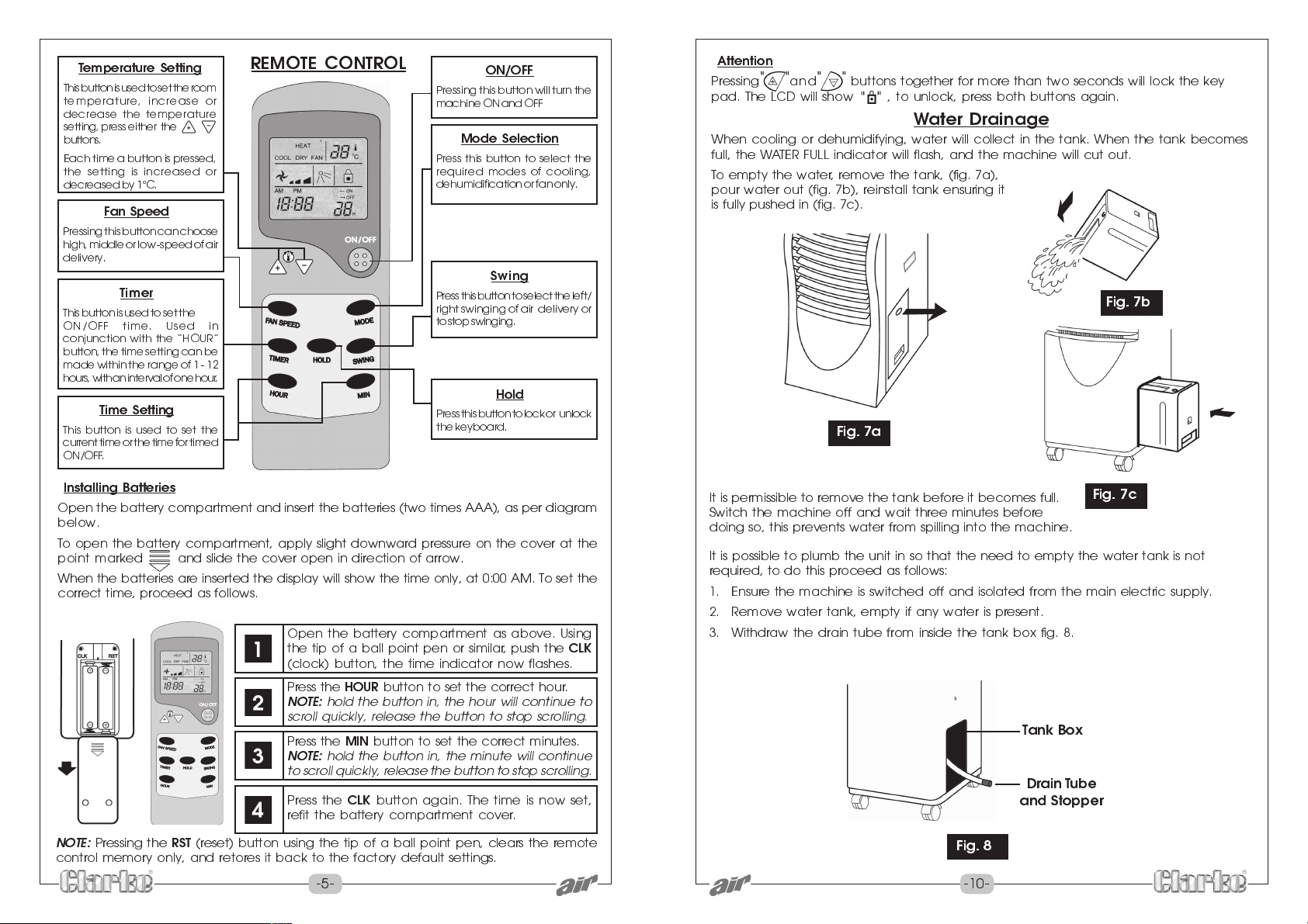
Temperature Setting
This button is used to set the room
temperature, increase or
decrease the temperature
setting, press either the
buttons.
Each time a button is pressed,
the setting is increased or
decreased by 1°C.
Fan Speed
Pressing this button can choose
high, middle or low -speed of air
delivery.
Timer
This button is used to set the
ON/OFF time. Used in
conjunction with the HOUR
button, the time setting can be
made within the range of 1 - 12
hours, with an interval of one hour.
Time Setting
This button is used to set the
current time or the time for timed
ON/OFF.
REMOTE CONTROL
ON/OFF
Pressing this button will turn the
machine ON and OFF
Mode Selection
Press this button to select the
required modes of cooling,
dehumidification or fan only.
Swing
Press this button to select the left/
right swinging of air delivery or
to stop swinging.
Hold
Press this button to lock or unlock
the keyboard.
Attention
Pressing and buttons together for more than two seconds will lock the key
pad. The LCD will show , to unlock, press both buttons again.
Water Drainage
When cooling or dehumidifying, water will collect in the tank. When the tank becomes
full, the WATER FULL indicator will flash, and the machine will cut out.
To empty the water, remove the tank, (fig. 7a),
pour water out (fig. 7b), reinstall tank ensuring it
is fully pushed in (fig. 7c).
Fig. 7b
Fig. 7a
Installing Batteries
Open the battery compartment and insert the batteries (two times AAA), as per diagram
below.
To open the battery compartment, apply slight downward pressure on the cover at the
point marked and slide the cover open in direction of arrow.
When the batteries are inserted the display will show the time only, at 0:00 AM. To set the
correct time, proceed as follows.
Open the battery compartment as above. Using
the tip of a ball point pen or similar, push the
CLK
(clock) button, the time indicator now flashes.
Press the
NOTE:
HOUR
button to set the correct hour.
hold the button in, the hour will continue to
scroll quickly, release the button to stop scrolling.
Press the
NOTE:
MIN
button to set the correct minutes.
hold the button in, the minute will continue
to scroll quickly, release the button to stop scrolling.
Press the
CLK
button again. The time is now set,
refit the battery compartment cover.
NOTE:
Pressing the
RST
(reset) button using the tip of a ball point pen, clears the remote
control memory only, and retores it back to the factory default settings.
-5- -10-
It is permissible to remove the tank before it becomes full.
Fig. 7c
Switch the machine off and wait three minutes before
doing so, this prevents water from spilling into the machine.
It is possible to plumb the unit in so that the need to empty the water tank is not
required, to do this proceed as follows:
1. Ensure the machine is switched off and isolated from the main electric supply.
2. Remove water tank, empty if any water is present.
3. Withdraw the drain tube from inside the tank box fig. 8.
Tank Box
Drain Tube
and Stopper
Fig. 8
Page 7
OPERATION
Cooling and Dehumidifying Operation
The operating range for cooling operation is, 17°C-31°C and the operating range for
dehumidifying is 20°C-31°C.
Connecting To The Electrical Supply
It is recommended to connect the mobile air conditioner to an electric supply not used
for other appliances.
Insert the plug into the 13amp socket, then press the (ON/OFF) button, the unit
should now run.
Cooling Operation
1. Ensure that the drain tank is properly installed in the unit.
2. Press the (Mode) button to choose the cooling mode, LCD will display
cool.
During the cooling operation, the exhaust duct should be directed to the outside
through an open window etc.
3. Repeatedly press the (Temp) button to set the room temperature.
4. Press the (Fan) button to select the fan speed, (High, Middle or Low).
5. Press the (Swing) button to adjust the air delivery direction, this can be
static in one direction or can be oscillating.
Press the swing button once, will be displayed in the LCD, and the air flow will
be oscillating from side to side. To set the air flow in one direction only, wait until the
air is blowing in the required direction, and press the swing button again.
NOTE: to maintain efficient cooling, draw the window blinds/curtains, if the room is
directly exposed to strong sun.
Also DO NOT site the air conditioner in direct sunlight, or other heat source.
Dehumidifying Operation
1. Ensure doors and windows are closed to aid the effectiveness of the unit.
2. Ensure the drain tank is correctly installed.
3. Repeatedly press the (Mode) button until the LCD reads DRY, in this mode
the fan speed cannot be adjusted.
NOTE: when used as a dehumidifier only, it is not necessary to use the exhaust duct.
Time Set Function
Automatic Start Time
Ensure the machine is switched off and is plugged into the main electrical supply,
1. Press the (Timer) button, the LCD will show , press the (time)
button and select the start time as required. The setting range is 1 - 12 hours.
Auto Swing Function
1. Press the (Swing) button, LCD will show , the vertical louvres will start to
swing automatically.
2. Press the (Swing) button again, the symbol , will disappear and the
vertical louvres will stop swinging.
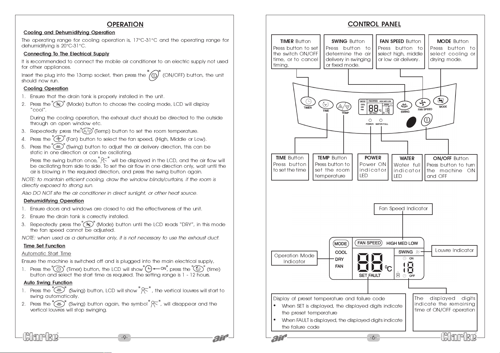
CONTROL PANEL
TIMER
Button
Press button to set
the switch ON/OFF
time, or to cancel
timing.
TIME
Button
Press button
to set the time
Operation Mode
Indicator
Display of preset temperature and failure code
When SET is displayed, the displayed digits indicate
the preset temperature
When FAULT is displayed, the displayed digits indicate
the failure code
SWING
Press button to
determine the air
delivery in swinging
or fixed mode.
TEMP
Button
Press button to
set the room
temperature
Button
Power ON
indicator
LED
F AN SPEED
Press button to
select high, middle
or low air delivery.
POWER
Fan Speed Indicator
Button
WATER
Water full
indicator
LED
The displayed digits
indicate the remaining
time of ON/OFF operation
MODE
Button
Press button to
select cooling or
drying mode.
ON/OFF
Press button to turn
the machine ON
and OFF
Button
Louvre Indicator
-9- -6-
Page 8
INSTALLATION
Siting the Machine
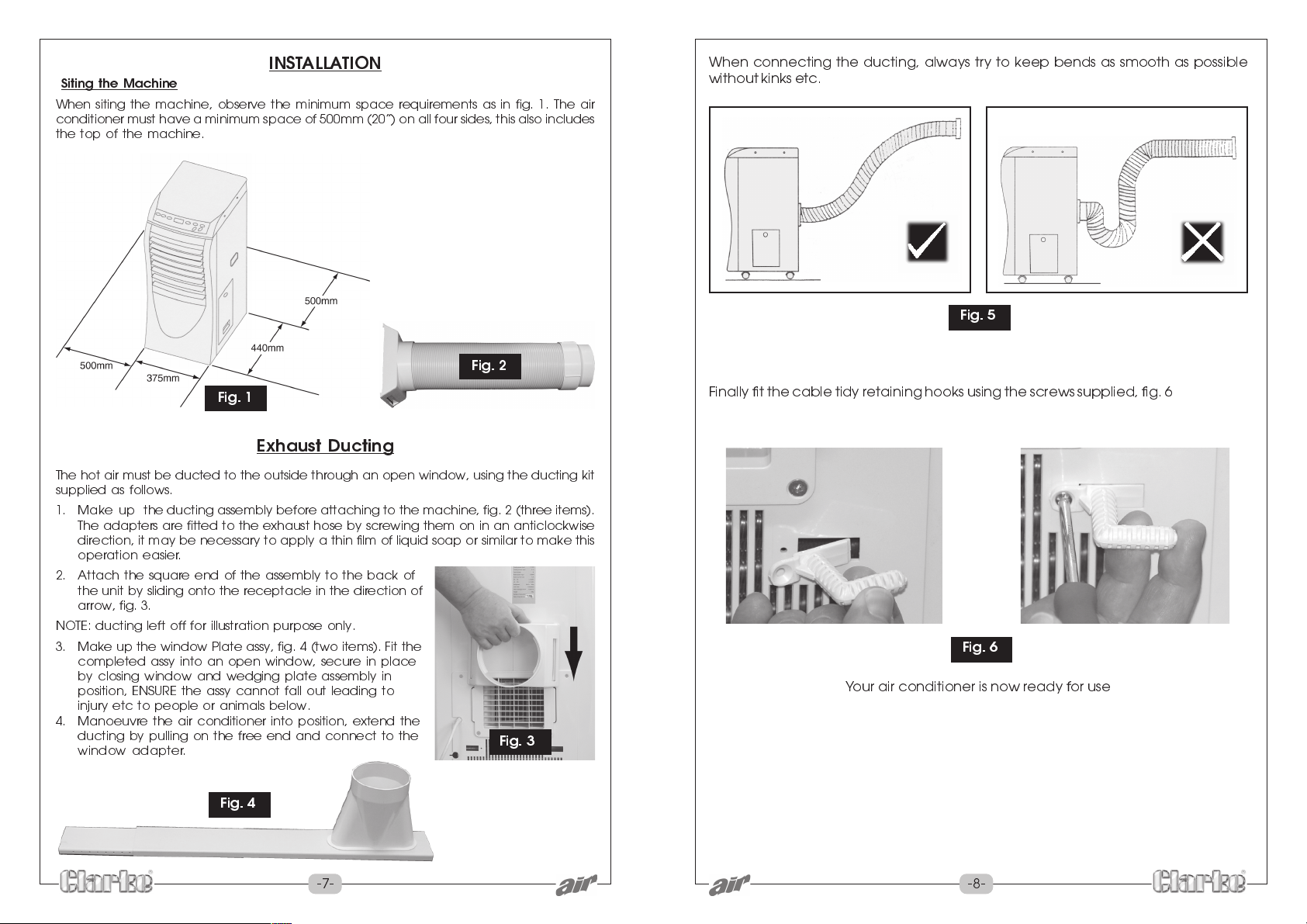
When siting the machine, observe the minimum space requirements as in fig. 1. The air
conditioner must have a minimum space of 500mm (20) on all four sides, this also includes
the top of the machine.
Fig. 2
Fig. 1
Exhaust Ducting
The hot air must be ducted to the outside through an open window, using the ducting kit
supplied as follows.
1. Make up the ducting assembly before attaching to the machine, fig. 2 (three items).
The adapters are fitted to the exhaust hose by screwing them on in an anticlockwise
direction, it may be necessary to apply a thin film of liquid soap or similar to make this
operation easier.
2. Attach the square end of the assembly to the back of
the unit by sliding onto the receptacle in the direction of
arrow, fig. 3.
NOTE: ducting left off for illustration purpose only.
3. Make up the window Plate assy, fig. 4 (two items). Fit the
completed assy into an open window, secure in place
by closing window and wedging plate assembly in
position, ENSURE the assy cannot fall out leading to
injury etc to people or animals below.
4. Manoeuvre the air conditioner into position, extend the
ducting by pulling on the free end and connect to the
window adapter.
Fig. 3
When connecting the ducting, always try to keep bends as smooth as possible
without kinks etc.
Fig. 5
Finally fit the cable tidy retaining hooks using the screws supplied, fig. 6
Fig. 6
Your air conditioner is now ready for use
Fig. 4
-7- -8-
 Loading...