

Page 1

AIR FILTER
MODEL NO: AF1000
PART NO: 6471160
OPERATION & MAINTENANCE
INSTRUCTIONS
1208
Page 2

INTRODUCTION
Thank you for purchasing this Clarke Air Filter.
Before you try to use this product, read this manual and follow the instructions
carefully. In doing so you will ensure your safety and the safety of others
around you. You can also look forward to a purchase that gives you long and
satisfactory service.
GUARANTEE
This product is guaranteed against faulty manufacture for a period of 12
months from the date of purchase. Please keep your receipt which will be
required as proof of purchase.
This guarantee is invalid if the product is found to have been abused or
tampered with in any way, or not used for the purpose for which it was
intended.
Faulty goods should be returned to their place of purchase, no product can
be returned to us without prior permission.
This guarantee does not effect your statutory rights.
2
Page 3

CONTENTS
Introduction ................................................................................2
Guarantee ..................................................................................2
Contents...................................................................................... 3
Electrical Connections ..............................................................4
Unpacking and Assembly ......................................................... 5
General safety rules................................................................... 5
Installation ................................................................................... 6
Remote Control..........................................................................10
Operation ...................................................................................11
Maintenance.............................................................................. 12
Specifications .............................................................................14
Exploded Parts Diagram ........................................................... 15
Parts List ....................................................................................... 16
Parts and servicing..................................................................... 17
Declaration of conformity......................................................... 18
Notes ...........................................................................................19
3
Page 4

ELECTRICAL CONNECTIONS
Connect the mains lead to a standard, 230 Volt (50Hz) electrical supply through an
approved 13 amp BS 1363 plug, or a suitably fused isolator switch.
WARNING: THIS APPLIANCE MUST BE EARTHED
IMPORTANT: The wires in the mains lead are coloured in accordance with the following
code:
Green & Yellow - Earth
Blue - Neutral
Brown - Live
As the colours of the flexible lead of this appliance may not correspond with the
coloured markings identifying terminals in your plug proceed as follows:
• Connect GREEN & YELLOW cord to terminal marked with a letter “E” or Earth
symbol “ ” or coloured GREEN or GREEN & YELLOW.
• Connect BROWN cord to terminal marked with a letter “L” or coloured RED.
• Connect BLUE cord to terminal marked with a letter “N” or coloured BLACK.
If this appliance is fitted with a plug which is moulded onto the electric cable (i.e. nonrewireable) please note:
1. The plug must be thrown away if it is cut from the electric cable. There is a danger of
electric shock if it is subsequently inserted into a socket outlet.
2. Never use the plug without the fuse cover fitted.
3. When replacing a detachable fuse carrier, ensure the correct replacement is used
(as indicated by marking or colour code).
4. Replacement fuse covers can be obtained from your local dealer or most electrical
stockists.
FUSE RATING
The fuse in the plug must be replaced with one of the same rating (13 amps) and this
replacement must be ASTA approved to BS1362.
We strongly recommend that this machine is connected to the mains supply via a
Residual Current Device (RCD)
If in any doubt, consult a qualified electrician. DO NOT attempt any repairs yourself.
4
Page 5

UNPACKING AND ASSEMBLY
Unpack your air filter and its accessories and make sure that the following
items are present. Should there be any damage caused during transit contact
your Clarke dealer immediately.
• 1 x Air filter with fitted filters
• 1 x Remote Control (with 2 AAA batteries)
• 4 x Rubber Feet
• 1 x Pack of fixings (4 x M10 mounting ring bolts, 8 x M6x4.8mm bolts,
8 x 6mm flat washers and 8 x 6mm spring washers)
• 1 x Instruction manual (this book)
Please dispose of any packaging responsibly. The cardboard packaging can
be recycled.
GENERAL SAFETY RULES
There is a serious risk of personal injury if you do not follow all instructions laid
down in this guide.
1. Before use, always inspect the machine and its’ mountings to ensure they
are in good condition. If any damaged or broken parts are found, the
machine should be removed from service and the parts renewed or
repaired before further use.
2. Keep tools and equipment out of the reach of young children.
3. Protect the machine from extreme weather conditions, i.e. frost and/or
high temperatures.
4. Do not wear loose clothing, ties or any items that may be sucked against
the air inlet.
5. Do not use the air filter in environments that have volatile fumes from fuel,
paints or thinners.
Do not block the air flow to the air filter.
5
Page 6

INSTALLATION
NOTE: The remote control system relies on an infra red beam, so before
setting up the air filter make sure the signal path for the remote
control is not obstructed by hanging objects or partition walls
Your "Air Filter System” can be set up in one of three ways.
• Workbench Mounted
• Wall Mounted
• Ceiling Mounted
WORKBENCH MOUNTING
1. Turn the air filter upside down.
2. Remove the sticky back from the bottom of each foot and place to each
cor
ner of the unit, press down firmly.
3. Turn the air filter upright and place on to a stable workbench.
CAUTION: IT IS ADVISABLE TO SEEK HELP WHEN MOVING THE UNIT.
6
Page 7

WALL MOUNTING
You can install your air filter unit in confined spaces by using the flange
brackets supplied with your unit.
WARNING: BEFORE MOUNTING THE AIR FILTER SYSTEM MAKE SURE THE
SURFACE YOU INTEND TO FIX IT TO CAN SUPPORT THE WEIGHT DO NOT
FIX TO SURFACES SUCH AS PLASTER BOARD.
FITTING THE MOUNTING BRACKETS
1. Lift the filter catch and remove the outer filter.
2. Position each of the flange brackets under the edge of the unit and line up
the mounting bracket holes.
3. Use a washer and spring washer as shown below and secure the bolts with
a 10mm spanner.
NOTE: The mounting holes are threaded, so lock nuts are not required.
4. Replace the outer filter.
After securing the flange brackets to the air filter, there are two options for
mounting the unit onto the wall. (shown on page 8)
CAUTION: YOU WILL REQUIRE ASSISTANCE TO LIFT THE AIR FILTER IN
POSITION
7
Page 8

WALL MOUNTING
1. Mark the position of the flange
brackets on the wall.
2. Drill 4 holes into the wall and place
a wall plug into each hole.
3. Screw the unit flush to the wall face
using suitab
ANGLE FRAME MOUNTING
You can also sit the air filter on a frame
as shown.
1. Mark the position of the flange
brackets on the frame shelf.
2. Drill 4 holes into the shelf.
3. Secure the air filter to the frame
using suitab
NOTE: Pleas
le quality bolts.
le quality bolts.
e make sure that the
frame is capable of
supporting the weight of the
air filter.
8
Page 9

CEILING MOUNTING
WARNING: ONLY USE GOOD QUALITY CHAINS OR CABLES TO SUSPEND,
THIS AIR FILTER FROM THE CEILING.
Your air filter system can be suspended from the ceiling using the four M10 ring
bolts supplied. You will require another four ring bolts for securing to the ceiling
rafters.
TO INSTALL
1. Remove the screw plugs from the air filter
bolts into the four mounting holes.
NOTE: You must replace the screw plugs on top to seal the unit, if you do
not intend to use the mounting ring bolt.
2. Fix the extra four mounting ring bolts to the ceiling.
3. Slide the chains or wires through the ring bolts so they are hanging down
freely.
CAUTION: SEEK HELP WHEN LIFTING & POSITIONING THE AIR FILTER
then screw the four M1O ring
9
Page 10

4. Raise the air filter system and
secure the four hanging chains
or cables to the unit.
NOTE: Before finally securing all
the fixings make sure the
air filter is level by using a
spirit level and adjust
accordingly.
REMOTE CONTROL
INSERTING THE BATTERIES
1. Slide the battery compartment cover in the direction of the arrow.
2. Insert 2 ‘AAA’ alkaline batteries into the compartment, taking note of
polarity markings inside.
3. Replace the battery compartment cover.
NOTE: Whe
NOTE: Always change both batteries at the same time.
n the remote control starts behaving erratically, change the
batteries.
the
CAUTION: IF YOU DO NOT INTEND TO USE THE AIR FILTER FOR A MONTH
OR MORE, REMOVE THE BATTERIES.
10
Page 11

OPERATION
TURNING THE AIR FILTER ON
1. Press the green ON/SPEED button on the remote control once.
• The fan will come on at low speed.
• The low fan speed indicator will light up on the control panel.
ADJUSTING THE FAN SPEED.
1. Press the ON/SPEED button on the remote control repeatedly to cycle
through
• The corresponding fan speed
SETTING THE TIMER
The air filter can be set to switch off automatically after a preset period.
You can select from 1 hour, 2 hours or 4 hours.
1. Press the TIME button on the remote control
delay.
• The corresponding time delay indicat
TURNING THE AIR FILTER OFF
the fan speeds (low, medium or high).
indicator will light up on the control
panel.
repeatedly to cycle select the
or will light up on the control
panel.
1. Press the OFF button on the remote control once.
• The air filter will stop.
11
Page 12
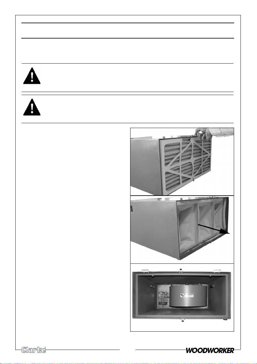
MAINTENANCE
CHANGING THE FILTER
WARNING: DISCONNECT THE UNIT FROM THE MAINS SUPPLY BEFORE
CHANGING/CLEANING THE FILTER.
WARNING: ALWAYS WEAR GOGGLES AND A DUST MASK WHEN
CHANGING/CLEANING THE FILTER.
1. Unclip the filter retaining latches.
2. Remove the outer filter.
• Dispose of the outer filter in a
refuse sack.
3.
Remove the inner filter and shake
it to remove any wood particles.
4. Rinse the inner filter in warm water,
th
en leave it to dry thoroughly.
5.
Vacuum the inside of the filter
housing.
6. When dry, replace the inner filter
and ins
7. Secure in place using the filter
retaining latches.
8. Wipe the outside of the machine
with
care to avoid any electrical
components.
tall a new outer filter.
a soft damp cloth, taking
12
Page 13

CHANGING THE FUSE
Fuse Cap
1.
Unscrew the fuse cap.
2. Carefully remove the fuse.
3. Replace with a new fuse see
“Parts List” on page 16 for the
type and part number.
13
Page 14
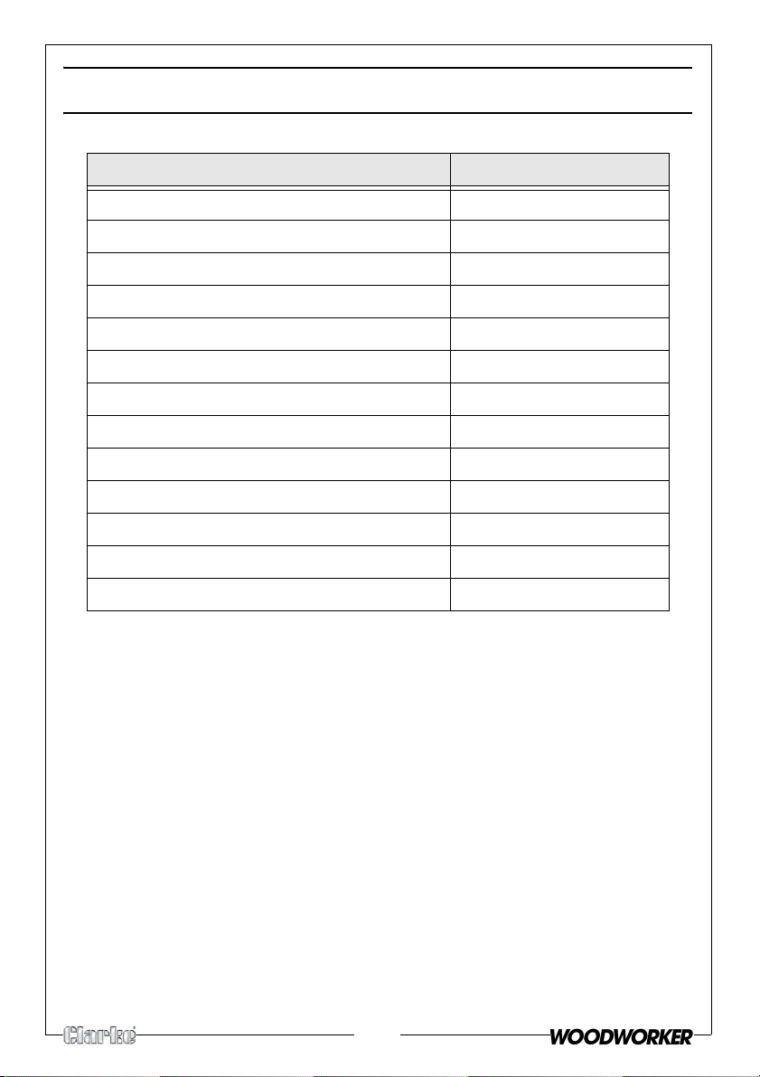
SPECIFICATIONS
AF1000
Motor Output 1/5 HP
Motor at Low Speed 780 rpm
Motor at Medium Speed 875 rpm
Motor at High Speed 960 rpm
Fan Noise Level 63 dB
Air Flow at Low Speed 556 CFM
Air Flow at Medium Speed 702 CFM
Air Flow at High Speed 1044 CFM
Filtration 2 Stage
Inner Filter 1 Micron
Outer Filter 5 Microns
Dimensions 775mm x 610mm x 310mm
Weight 25 Kg
14
Page 15

EXPLODED PARTS DIAGRAM
15
Page 16

PARTS LIST
NO DESCRIPTION PART NO NO DESCRIPTION PAR T N O
1 Remote Control QBAF100001 29 Handle QBAF100029
2 Label QBAF100002 30 Primary Filter 5-micron QBAF100030
3 Remote Control Cover QBAF100003 31 Foam Seal 1/4" X 1 " X 70" QBAF100031
4 AAA Batteries QBAF100004 32 Secondary Filter 1 Micron QBAF100032
5 Fuse Holder QBAF100005 33 Clip Set QBAF100033
6 8A Fuse QBAF100006 34 Capacitor QBAF100034
7 Power Cord QBAF100007 35 Insulator QBAF100035
8 Strain Relief QBAF100008 36 Capacitor Clamp QBAF100036
9 Control Panel QBAF100009 37 Motor QBAF100037
10 Philip Hd Scr M4-0.7 X 10 QBAF100010 38 Hex Locking Nut M5-0.8 QBAF100038
11 Label QBAF100011 39 Flange QBAF100039
12 Pc Board QBAF100012 40 Spacer QBAF100040
13 Philip Hd Scr M3-0.45 X 6.5 QBAF100013 41 Sleeve QBAF100041
14 Spacer QBAF100014 42 Flat Washer 6mm QBAF100042
15 Philip Hd Scr (Special) QBAF100015 43 Hex Bolt M6-1.0 X 30 QBAF100043
16 Ext Tooth Washer 4mm QBAF100016 45 Flange Bracket QBAF100045
17 Hex Nut M4-0.75 QBAF100017 46 Flat Washer 6mm QBAF100046
18 Flat Washer 4mm QBAF100018 47 Hex Bolt M6-1.0 X 10 QBAF100047
19 Lock Washer 4mm QBAF100019 48 Fan QBAF100048
20 Philip Hd Scr M4-0.75 X 6 QBAF100020 49 Key 4 X 4 X 20mm QBAF100049
21 Pc Wiring Harness QBAF100021 50 Hex Bolt M8-1.25 X12 QBAF100050
22 Bolt (Special) M3-0.45 X 6.5
23 Eye Bolt M6-1.0 X 20 QBAF100023 52 Cap Screw M6-1.0 X 20 (Lh) QBAF100052
24 Housing QBAF100024 53 Fan Housing QBAF100053
25 Mount And Bolt Bag QBAF100025 54 Tapping S cr ew QBAF100054
26 Rivet Nut M6 X 8 QBAF100026 55 Lock Washer 6mm QBAF100055
27 Flat Washer 6mm QBAF100027 56 Philip Hd Scr M6-1.0 X 16 QBAF100056
28 Rubber Foot QBAF100028
QBAF100022 51 Flange Disk 6.5 X 44mm QBAF100051
16
Page 17

PARTS AND SERVICING
For Parts & Servicing, please contact your nearest dealer, or
CLARKE International, on one of the following numbers.
PARTS & SERVICE TEL: 020 8988 7400
PARTS & SERVICE FAX: 020 8558 3622
or e-mail as follows:
PARTS: Parts@clarkeinternational.com
SERVICE: Service@clarkeinternational.com
17
Page 18

DECLARATION OF CONFORMITY
DECLARATION OF CONFORMITY
This is an important document and should be retained.
AF1000-RV1.doc Page 1 of 1
We declare that this product complies with the following directives:
89/336/EEC Electromagnetic Compatibility directive, (amended 2004/108/EC).
73/23/EEC Low Voltage Equipment directive ( amended by 93/68/EEC).
The Following Standards have been applied to the product:
BS EN 55014-1:2001+A1 BS EN 55014-2:1997+A1
BS EN 61000-3-3:1995+A1 BS EN 61000-3-2:2000
The technical documentation required to demonstrate that the products meet the
requirements of the Low Voltage Equipment directive has been compiled and is available
for inspection by the relevant enforcement authorities.
The CE mark was first applied in: 2003
Product Description: Air Filter
Model number(s): AF 1000
Serial / batch Number: Current Manufacture.
Date of Issue: 28/04/2008
Signed
A.C. AIKEN
Senior Manager Clarke International.
18
Page 19

NOTES
19
Page 20

 Loading...