

Page 1
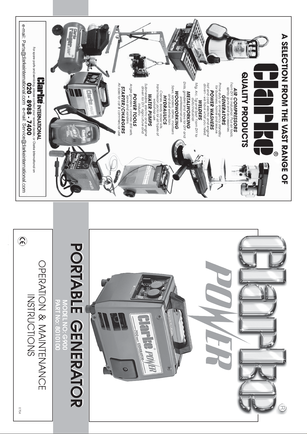
PORTABLE GENERATOR
PORTABLE GENERATOR
OPERATION & MAINTENANCE
INSTRUCTIONS
PART No: 8010100
MODEL NO: G900
0704
Page 2
-1-
Please note that the details and specifications contained herein, are correct at the time of going to print. However,
CLARKE International reserve the right to change specifications at any time without prior notice.
-14-
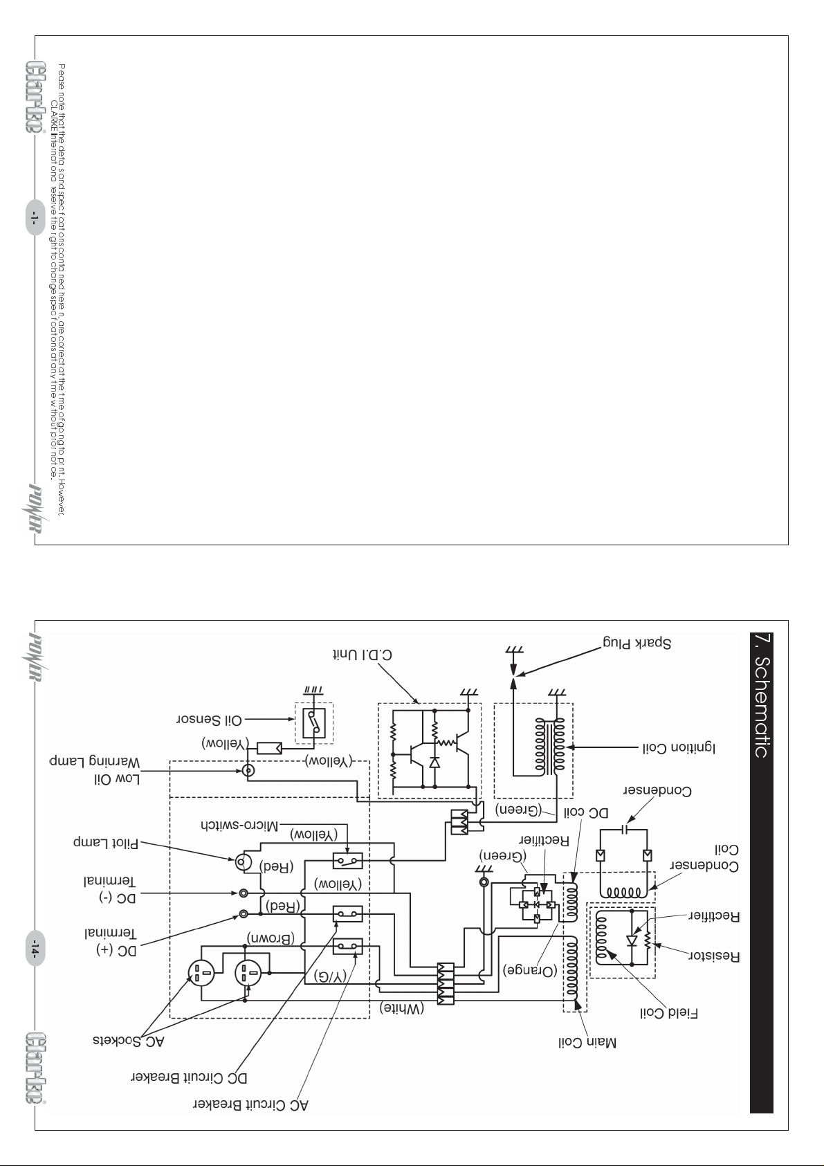
7. Schematic
Page 3
-13- -2-
Dry Weight.
22.5kg (49½lbs).
Dimensions.
Over Current
Protection. Circuit breaker.
L x W x H 365 x 265 x 345mm (14½ x 10½ x 13½)
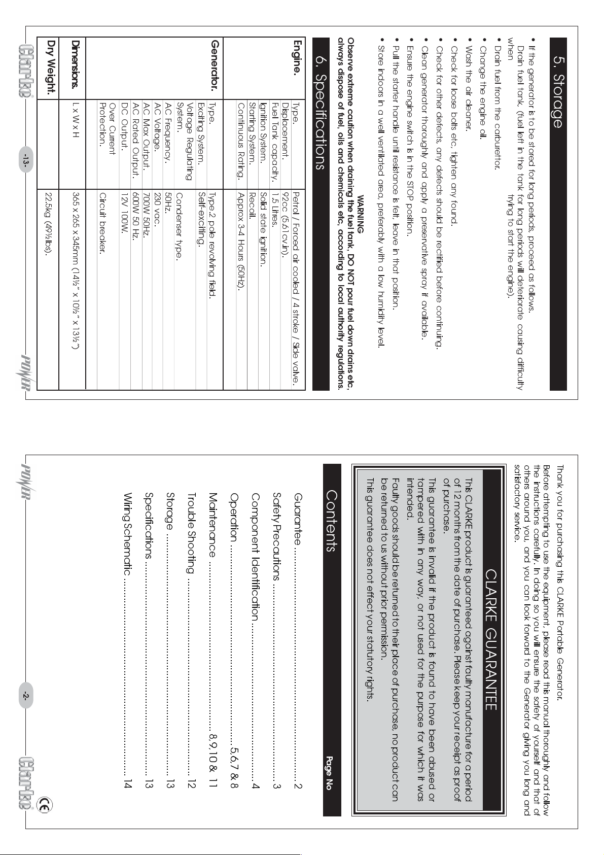
Generator.
Ignition System. Solid state ignition.
Starting System. Recoil.
Continuous Rating. Approx 3-4 Hours (50Hz).
Type. Type.2 pole revolving field.
Exciting System.
Voltage Regulating
System.
AC Frequency. 50Hz.
AC Voltage. 230 vac.
AC Max Output. 700W 50Hz.
AC Rated Output. 600W 50 Hz.
DC Output. 12V 100W.
Self-exciting.
Condenser type.
Engine.
Type. Petrol / Forced air cooled / 4 stroke / Side valve.
Displacement. 92cc (5.61cv.in).
Fuel Tank capacity. 1.5 Litres.
always dispose of fuel, oils and chemicals etc, according to local authority regulations.
Store indoors in a well ventilated area, preferably with a low humidity level.
Pull the starter handle until resistance is felt, leave in that position.
6. Specifications
W ARNING
Clean generator thoroughly and apply a preservative spray if available.
Ensure the engine switch is in the STOP position.
Wash the air cleaner.Check for loose bolts etc, tighten any found.
Check for other defects, any defects should be rectified before continuing.
Drain fuel from the carburettor.Change the engine oil.
If the generator is to be stored for long periods, proceed as follows.
Drain fuel tank, (fuel left in the tank for long periods will deteriorate causing difficulty
5. Storage
when trying to start the engine).
Observe extreme caution when draining the fuel tank, DO NOT pour fuel down drains etc,
Thank you for purchasing this CLARKE Portable Generator.
Before attempting to use the equipment, please read this manual thoroughly and follow
the instructions carefully. In doing so you will ensure the safety of yourself and that of
others around you, and you can look forward to the Generator giving you long and
satisfactory service.
This CLARKE product is guaranteed against faulty manufacture for a period
of 12 months from the date of purchase. Please keep your receipt as proof
of purchase.
This guarantee is invalid if the product is found to have been abused or
tampered with in any way, or not used for the purpose for which it was
intended.
Faulty goods should be returned to their place of purchase, no product can
be returned to us without prior permission.
This guarantee does not effect your statutory rights.
Guarantee .................................................................................... 2
Safety Precautions .......................................................................3
Component Identification......................................................... 4
Operation ........................................................................ 5,6,7 & 8
Maintenance ............................................................. 8,9,10 & 11
Trouble Shooting ....................................................................... 12
Storage ....................................................................................... 13
Specifications ............................................................................. 13
Wiring Schematic .......................................................................14
Contents
CLARKE GUARANTEE
Page No
Page 4

observed to ensure people an animals in the surrounding areas are not affected.
-3- -12-
Exhaust fumes contain toxic gases. Extreme care must be
if connected, could lead to a malfunction, even worse, a
fire could result.
W ARNING
13.
area.
NEVER
connect the generator to a residual power source,
insufficient ventilation, such as a tunnel etc, ensure the
exhaust pipe is directed towards a well ventilated open
11.
12.
NEVER
NEVER
operate the generator when raining or snowing.
operate in enclosed area where there is
10.
NEVER
cover or enclose in box etc.
operate the generator indoors.
8.
NEVER
up and allowed to dry thoroughly before starting the generator.9.NEVER
overfill the tank, fill to the specified level only.
7.
celluloid items, explosives etc).
NEVER
when refuelling.
smoke, use a naked flame or allow others to do so
6.
best and safest performance. Follow maintenance instructions.
AL WAYS
the generator. Surrounding areas should be free of
inflammables and hazardous materials (lubricants,
allow at least 1 metre (3ft) clearance around
5.
ALWAYS
maintain machine in top condition. Keep clean for the
4.
ALWAYS
etc.
switch the machine off before servicing and when refuelling
Consult your local dealer.3.ALWA YS
while the generator is operating.
use the generator on a flat level surface. A void tilting or moving
of parts, mountings, and any other condition that may
affect the machines operation. Any damage should be
properly repaired or the part replaced. If in doubt,
2.
AL WAYS
any damaged part, should be checked to ensure that
it will operate properly, and perform its intended
function. Check for alignment of moving parts, breakage
check for damage. Before using the machine,
1.
ignored, personal injury to the operator or damage to property, may result.
ALWAYS
hazards peculiar to it. Read and become familiar with the entire
operating manual.
Learn the machines applications, limitations and the specific potential
personal injury. However, if normal safety precautions are overlooked or
and use. Exercising respect and caution will considerably lessen the risk of
As with all machinery, there are certain hazards involved with their operation
1. Safety Precautions
WARNING:
Any spillages must be cleaned
If problems persist, contact Clarke service department for advice.
SERVICE: Service@clarkeinternational.com
PARTS: Parts@clarkeinternational.com
PARTS & SERVICE TEL: 020 8988 7400
Faulty connection at
the appliance.
Circuit breaker tripped. Check the wattage of connected appliance is
No power supplied to the appliance
DO NOT
use the machine.
Oil warning lamp
flashing.
3ft
3ft
3ft
3ft
Engine Fails To Start
Engine switch and or
choke lever are
Spark plug !
to the generator.
Fuel tank empty. Check fuel level and top up as required.
Appliance connected
incorrectly set.
5. Trouble Shooting
or e-mail as follows:
Check connections and make good if faulty
one found.
within the permissible tolerance level of the
generator , if OK, reset the tripped circuit breaker
and resume as normal.
Fit new spark plug
Check oil level and top up as required.
Check spark plug is connected correctly.
Remove spark plug and clean.
If connected, turn off the power switch at the
appliance or disconnect completely.
when engine warms up.
lever to its uppermost position (CHOKE).
Return choke lever to its normal position (RUN)
Set engine switch to RUN, move the choke
Page 5
adjusting screw Fig. 13b (cut away view), to view the screw when making this adjustment
is possible by looking through the open spark plug cover.
Replace rubber grommet when finished.
contact your nearest Clarke dealer for advice.
If it is necessary to make adjustments, remove the rubber grommet to gain access to the
at the factory. before attempting to make further adjustments, we recommend that you
NOTE: It shouldnt be necessary to adjust the carburettor air screw as this has been preset
Carburettor Adjustment
damage the porcelain.
Champion - RCJ8
Check for correct gap between
the electrodes. Adjust gap to 0.6
to 0.7mm (0.02 to 0.03) by
reforming the electrode (Fig. 12).
Recommended replacement
plug type:
NGK - BMR4A
Refit spark plug in reverse order,
DO NOT overtighten and take
extra care not to break or
ab
Using a plug cleaner or wire brush, clean plug
electrode of burnt or deposited carbon.
Using the box spanner/plug spanner Fig. 11,
loosen and remove the plug by turning in an
anticlockwise position.
-11- -4-
Fig. 13
Porcelain
Fig. 12
Spark Plug Gap
0.6~0.7mm
(0.02~0.03)
or
Fig. 11
Electrode
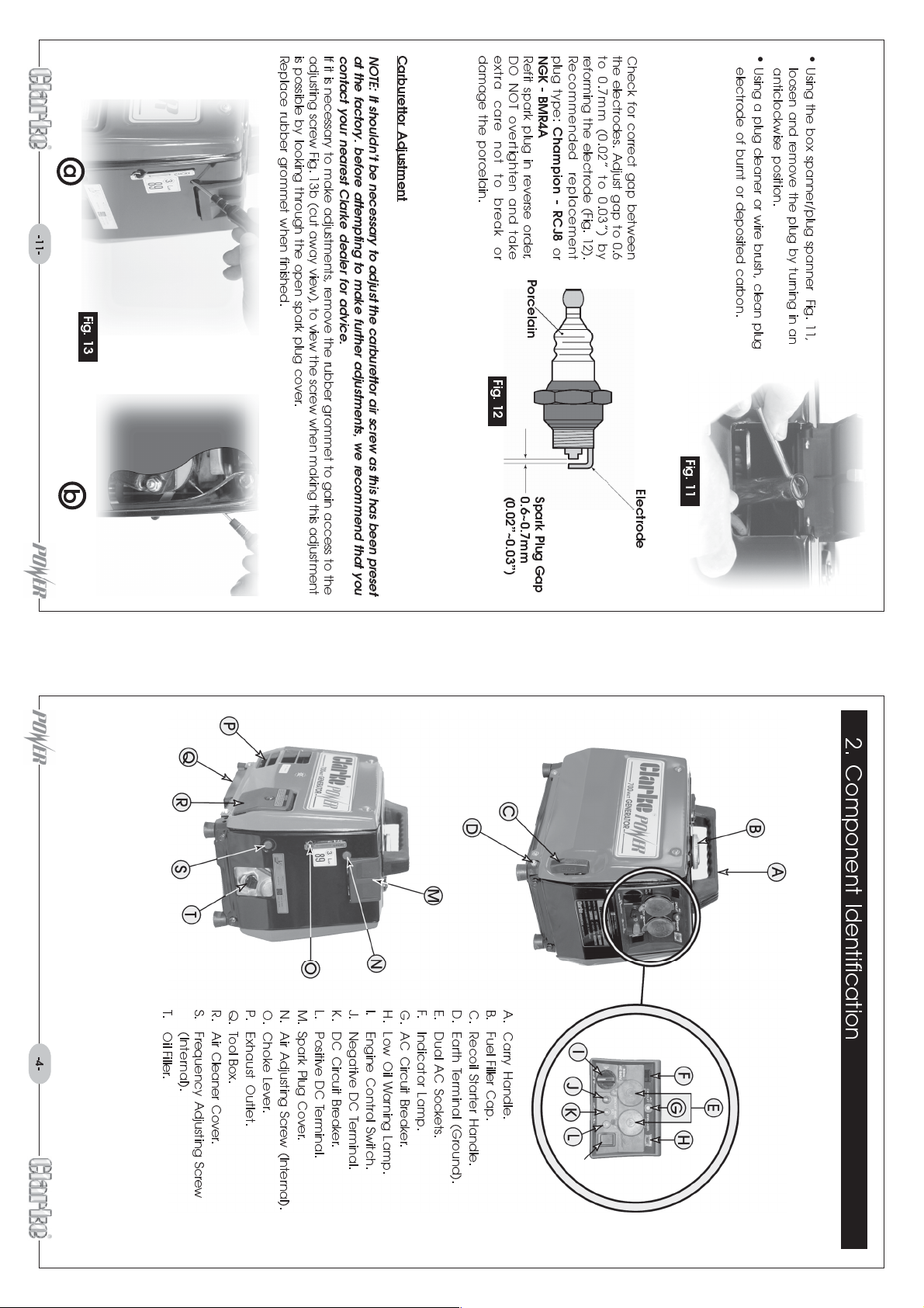
T. Oil Filler.
(Internal).
R. Air Cleaner Cover.
S. Frequency Adjusting Screw
Q. Tool Box.
O. Choke Lever.
P. Exhaust Outlet.
L. Positive DC Terminal.
M. Spark Plug Cover.
N. Air Adjusting Screw (Internal).
K. DC Circuit Breaker.
I. Engine Control Switch.
J. Negative DC Terminal.
G. AC Circuit Breaker.
H. Low Oil Warning Lamp.
E. Dual AC Sockets.
F. Indicator Lamp.
C. Recoil Starter Handle.
D. Earth Terminal (Ground).
A. Carry Handle.
B. Fuel Filler Cap.
2. Component Identification
Page 6
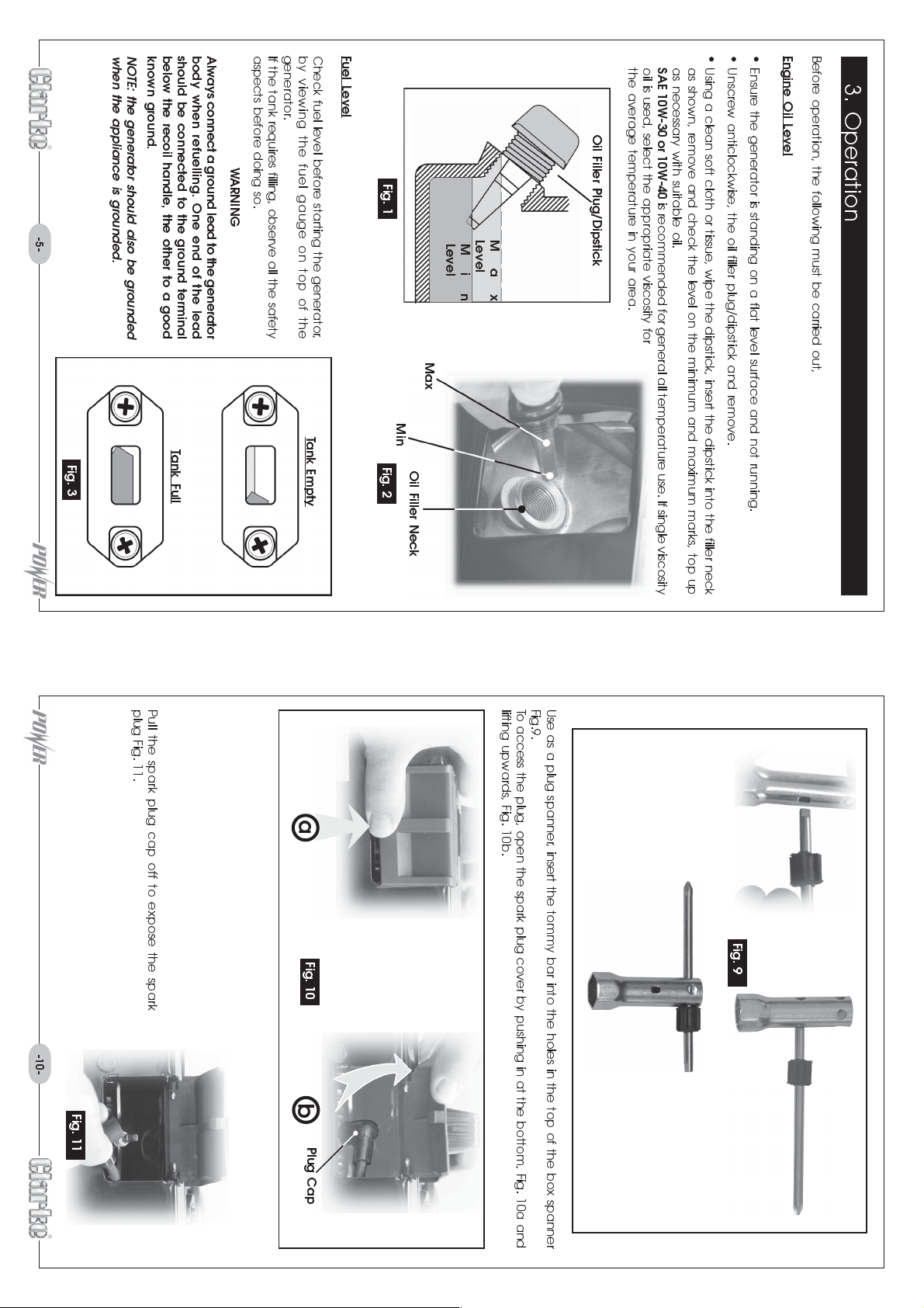
known ground.
NOTE: the generator should also be grounded
when the appliance is grounded.
should be connected to the ground terminal
below the recoil handle, the other to a good
Always connect a ground lead to the generator
body when refuelling. One end of the lead
aspects before doing so.
WARNING
generator.
If the tank requires filling, observe all the safety
by viewing the fuel gauge on top of the
Fuel Level
Check fuel level before starting the generator,
oil is used, select the appropriate viscosity for
the average temperature in your area.
SAE 10W-30 or 10W-40
as necessary with suitable oil.
as shown, remove and check the level on the minimum and maximum marks, top up
Using a clean soft cloth or tissue, wipe the dipstick, insert the dipstick into the filler neck
Ensure the generator is standing on a flat level surface and not running.
Unscrew anticlockwise, the oil filler plug/dipstick and remove.
Before operation, the following must be carried out,
Engine Oil Level
3. Operation
Oil Filler Plug/Dipstick
Fig. 1
is recommended for general all temperature use. If single viscosity
-5- -10-
Max
Level
Min
Level
Max
Tank Full
Tank Empty
Fig. 3
Min
Fig. 2
Oil Filler Neck
Fig. 11
plug Fig. 11.
Pull the spark plug cap off to expose the spark
a
b
Fig. 10
Plug Cap
lifting upwards, Fig. 10b.
To access the plug, open the spark plug cover by pushing in at the bottom, Fig. 10a and
Use as a plug spanner , insert the tommy bar into the holes in the top of the box spanner
Fig.9.
Fig. 9
Page 7
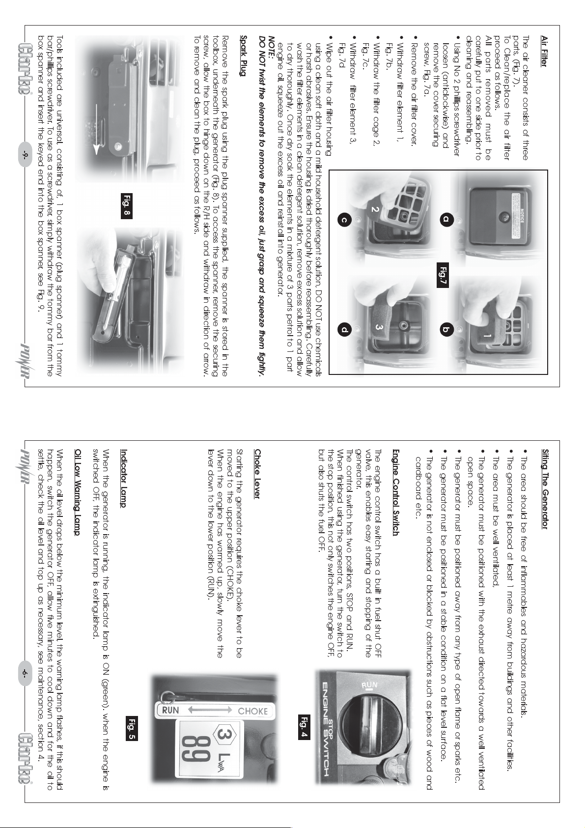
-9- -6-
box spanner and insert the keyed end into the box spanner , see Fig. 9.
Tools included are universal, consisting of, 1 box spanner (plug spanner) and 1 tommy
bar/phillips screwdriver. To use as a screwdriver , simply withdraw the tommy bar from the
Fig. 7b.
screw, Fig. 7a.
Remove the air filter cover.Withdraw filter element 1,
To remove and clean the plug, proceed as follows.
Fig. 8
wash the filter elements in a clean detergent solution, remove excess solution and allow
to dry thoroughly. Once dry soak the elements in a mixture of 3 parts petrol to 1 part
engine oil, squeeze out the excess oil and reinstall into generator.
NOTE:
DO NOT twist the elements to remove the excess oil, just grasp and squeeze them tightly.
Spark Plug
Remove the spark plug using the plug spanner supplied, the spanner is stored in the
toolbox, underneath the generator (Fig. 8). To access the spanner, remove the securing
screw, allow the box to hinge down on the R/H side and withdraw in direction of arrow.
Wipe out the air filter housing
using a clean soft cloth and a mild household detergent solution, DO NOT use chemicals
or harsh abrasives. Ensure the housing is dried thoroughly before reassembling. Carefully
Fig. 7d
Withdraw the filter cage 2,
Fig. 7c.
Withdraw filter element 3,
Using No 2 phillips screwdriver
loosen (anticlockwise) and
remove the cover securing
Air Filter
The air cleaner consists of three
parts, (Fig. 7).
To Clean/replace the air filter
proceed as follows.
All parts removed must be
carefully put to one side prior to
cleaning and reassembling.
2
c
a
Fig.7
generator.
The control switch has two positions, STOP and RUN.
valve, this enables easy starting and stopping of the
3
The engine control switch has a built in fuel shut OFF
Engine Control Switch
d
When finished using the generator, turn the switch to
the stop position, this not only switches the engine OFF,
Indicator Lamp
When the generator is running, the indicator lamp is ON (green). when the engine is
switched OFF, the indicator lamp is extinguished.
Oil Low Warning Lamp
When the oil level drops below the minimum level, the warning lamp flashes, if this should
happen, switch the generator OFF, allow five minutes to cool down and for the oil to
settle, check the oil level and top up as necessary, see maintenance, section 4.
lever down to the lower position (RUN).
Choke Lever
Starting the generator requires the choke lever to be
moved to the upper position (CHOKE).
When the engine has warmed up, slowly move the
but also shuts the fuel OFF.
cardboard etc.
The generator is not enclosed or blocked by obstructions such as pieces of wood and
b
The generator must be positioned in a stable condition on a flat level surface.
The generator must be positioned away from any type of open flame or sparks etc.
1
The generator must be positioned with the exhaust directed towards a well ventilated
open space.
The area should be free of inflammables and hazardous materials.
The generator is placed at least 1 metre away from buildings and other facilities.
The area must be well ventilated,
Siting The Generator
Fig. 5
Fig. 4
Page 8
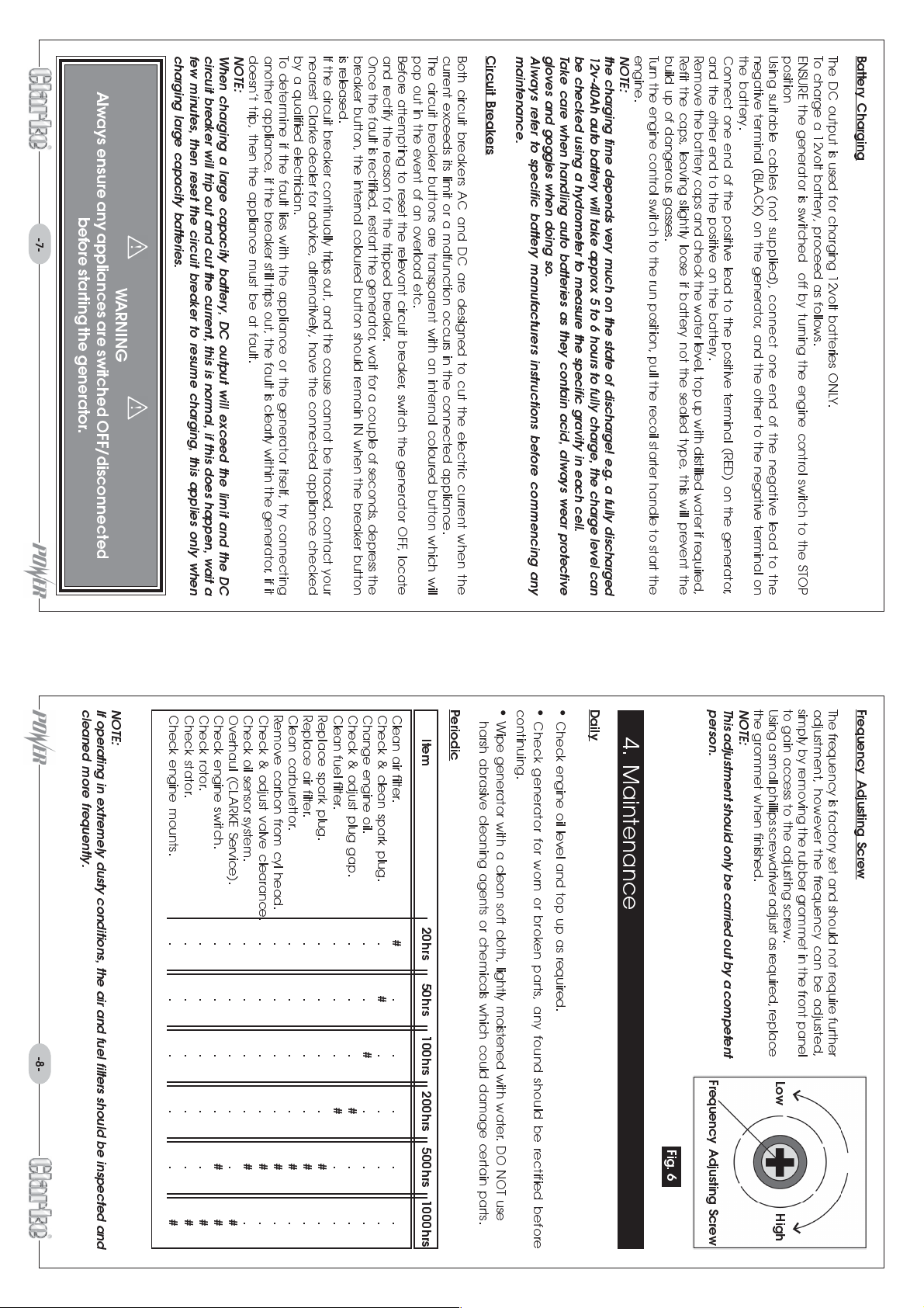
-7- -8-
charging large capacity batteries.
Always ensure any appliances are switched OFF/disconnected
before starting the generator.
WARNING
circuit breaker will trip out and cut the current, this is normal, if this does happen, wait a
few minutes, then reset the circuit breaker to resume charging, this applies only when
When charging a large capacity battery, DC output will exceed the limit and the DC
doesnt trip, then the appliance must be at fault.
NOTE:
by a qualified electrician.
To determine if the fault lies with the appliance or the generator itself, try connecting
another appliance, if the breaker still trips out, the fault is clearly within the generator, if it
is released.
If the circuit breaker continually trips out, and the cause cannot be traced, contact your
nearest Clarke dealer for advice, alternatively, have the connected appliance checked
Once the fault is rectified, restart the generator, wait for a couple of seconds, depress the
breaker button, the internal coloured button should remain IN when the breaker button
and rectify the reason for the tripped breaker.
pop out in the event of an overload etc.
Before attempting to reset the relevant circuit breaker, switch the generator OFF , locate
Both circuit breakers AC and DC are designed to cut the electric current when the
current exceeds its limit or a malfunction occurs in the connected appliance.
The circuit breaker buttons are transparent with an internal coloured button which will
Always refer to specific battery manufacturers instructions before commencing any
maintenance.
Circuit Breakers
be checked using a hydrometer to measure the specific gravity in each cell.
Take care when handling auto batteries as they contain acid, always wear protective
gloves and goggles when doing so.
NOTE:
the charging time depends very much on the state of discharge! e.g. a fully discharged
12v-40Ah auto battery will take approx 5 to 6 hours to fully charge, the charge level can
build up of dangerous gasses.
Turn the engine control switch to the run position, pull the recoil starter handle to start the
engine.
Remove the battery caps and check the water level, top up with distilled water if required,
Refit the caps, leaving slightly loose if battery not the sealed type, this will prevent the
the battery.
Connect one end of the positive lead to the positive terminal (RED) on the generator,
and the other end to the positive on the battery.
negative terminal (BLACK) on the generator, and the other to the negative terminal on
position
Using suitable cables (not supplied), connect one end of the negative lead to the
To charge a 12volt battery, proceed as follows.
ENSURE the generator is switched off by turning the engine control switch to the STOP
The DC output is used for charging 12volt batteries ONLY.
Battery Charging
NOTE:
If operating in extremely dusty conditions, the air and fuel filters should be inspected and
cleaned more frequently.
Clean air filter.
Check & clean spark plug. .
Change engine oil. . .
Check & adjust plug gap. . . .
Clean fuel filter . . . .
Replace spark plug. ....
Replace air filter. ....
Clean carburettor. ....
Remove carbon from cyl head. ....
Check & adjust valve clearance. ....
Check oil sensor system. ....
Overhaul (CLARKE Service). .....
Check engine switch. ....
Check rotor. .....
Check stator. .....
Check engine mounts. .....
Item 20hrs 50hrs 100hrs 200hrs 500hrs 1000hrs
#
#
.....
#
....
#
#
...
#
#
#
#
#
#
##
..
..
Periodic
harsh abrasive cleaning agents or chemicals which could damage certain parts.
continuing.
Wipe generator with a clean soft cloth, lightly moistened with water. DO NOT use
Check engine oil level and top up as required.
Check generator for worn or broken parts, any found should be rectified before
Daily
4. Maintenance
Fig. 6
NOTE:
This adjustment should only be carried out by a competent
person.
Frequency Adjusting Screw
Frequency Adjusting Screw
The frequency is factory set and should not require further
adjustment, however the frequency can be adjusted,
simply by removing the rubber grommet in the front panel
to gain access to the adjusting screw.
Using a small phillips screwdriver adjust as required, replace
the grommet when finished.
#
.
.
.
.
.
.
#
#
#
HighLow
 Loading...