

Page 1
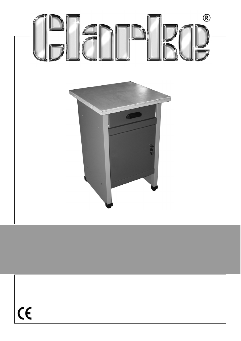
WORKBENCH WITH DRAWER LOCKABLE
CUPBOARD
MODEL NO: CWB57
PART NO: 7642010
ASSEMBLY
INSTRUCTIONS
LS0115
Page 2
INTRODUCTION
Thank you for purchasing this CLARKE product.
Before attempting to use this product, please read this manual thoroughly and
follow the instructions carefully. In doing so you will ensure the safety of yourself
and that of others around you, and you can look forward to your purchase
giving you long and satisfactory service.
GUARANTEE
This product is guaranteed against faulty manufacture for a period of 12
months from the date of purchase. Please keep your receipt which will be
required as proof of purchase.
This guarantee is invalid if the product is found to have been abused or
tampered with in any way, or not used for the purpose for which it was
intended.
Faulty goods should be returned to their place of purchase, no product can
be returned to us without prior permission.
This guarantee does not effect your statutory rights.
SPECIFICATION
Dimensions (w x d x h) 570 x 600 x 870 mm
Weight (Empty) 23 kg
Maximum Load Per Drawer 10 kg
Maximum Load Total 60 kg
2
Parts & Service: 020 8988 7400 / E-mail: [email protected] or [email protected]
Page 3
CONTENTS
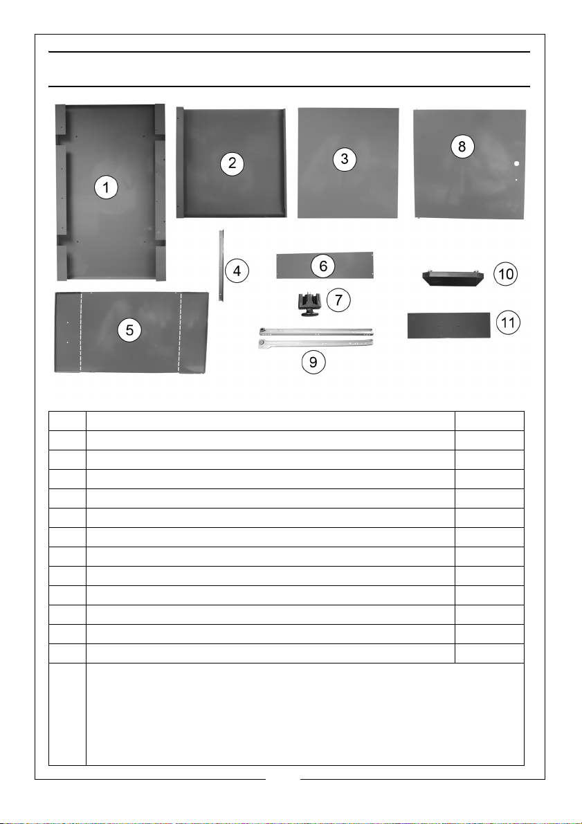
No Description Qty
1Side Panel 2
2 Top/Bottom Panel 2
3Rear Panel 1
4Door Jamb 1
5 Drawer Base 1
6 Drawer Sides 2
7Feet 4
8Door 1
9 Drawer Runners and Guides 2 sets
10 Drawer Handle 1
11 Red Drawer Front 1
12 Wooden Top (Not Shown 1
13 Fixings kit
12 x M5x10 round head bolt set
19 x M4x8 flat head bolt set
4 x M6x25 hex head self tap screw set
1 x M5x8 round head bolt set
2 x M4x10 round head self tap screw set
1 x M6x16 hex socket cap screw set
3
Parts & Service: 020 8988 7400 / E-mail: [email protected] or [email protected]
Page 4
ASSEMBLY
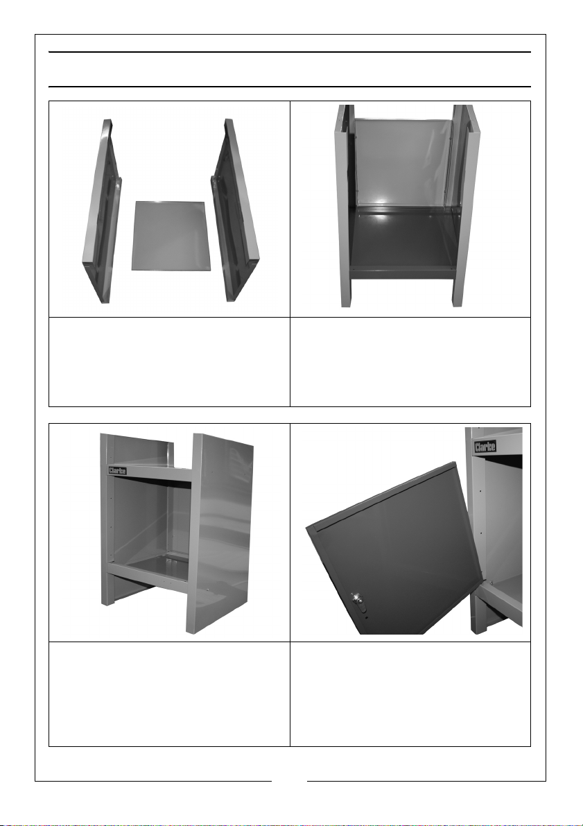
1. Fit the two side panels (1) to the
rear panel (3) as shown, use the
fixings (large nuts and large bolts)
supplied to secure in place.
2. Do not tighten fully at this stage.
4. Insert the Top Panel (2) as shown
and fix in place using the large
nuts, large bolts and washers
supplied.
3. Insert the Bottom Panel (2) as
shown and fix in place using the
large nuts, large bolts and
washers supplied.
5. Place the door pin into the hole
on the bottom panel as shown.
6. The allen screw, washer and nut
supplied act as the second hinge
pin, and must be fitted though
the hole in the top panel.
4
Parts & Service: 020 8988 7400 / E-mail: [email protected] or [email protected]
Page 5
7. Fit the door jamb (4) to the
opposite side to the hinge pin.
8. Fully tighten all fixings.
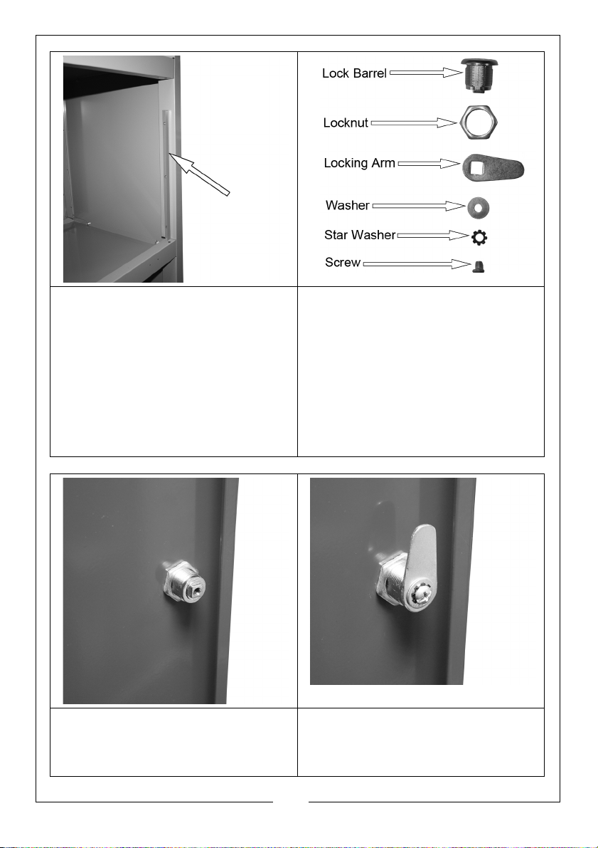
9. If the lock is fitted to the door
already, go to step 16.
10. Place the key in the lock and turn
it so that the window on the front
of the lock turns green.
11. Remove the screw and star
washer from the rear of the lock.
12. Remove the washer and locking
arm.
13. Remove the locknut from the
lock barrel.
14. Insert the lock barrel with the
green window at the top through
the door and secure using the
15. Replace the locking arm and
washer and secure using the star
washer and screw.
locknut as shown.
5
Parts & Service: 020 8988 7400 / E-mail: [email protected] or [email protected]
Page 6
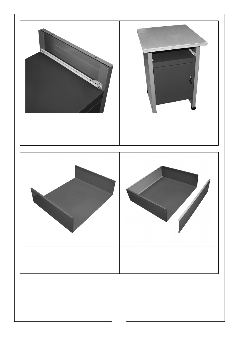
16. Fit one half of the drawer guides
(9) into position as shown and
use the small machine screws
and nuts to secure in place.
17. Fit the door knob.
18. Fit the wooden top (12) to the
workbench using the coach bolts
and washers provided.
19. Fold up the ends of the drawer
base (5) along the creases as
shown.
20. Fit the drawer sides (6) and
secure to the drawer base (5)
using the small machine screws
and nuts to secure.
6
Parts & Service: 020 8988 7400 / E-mail: [email protected] or [email protected]
Page 7
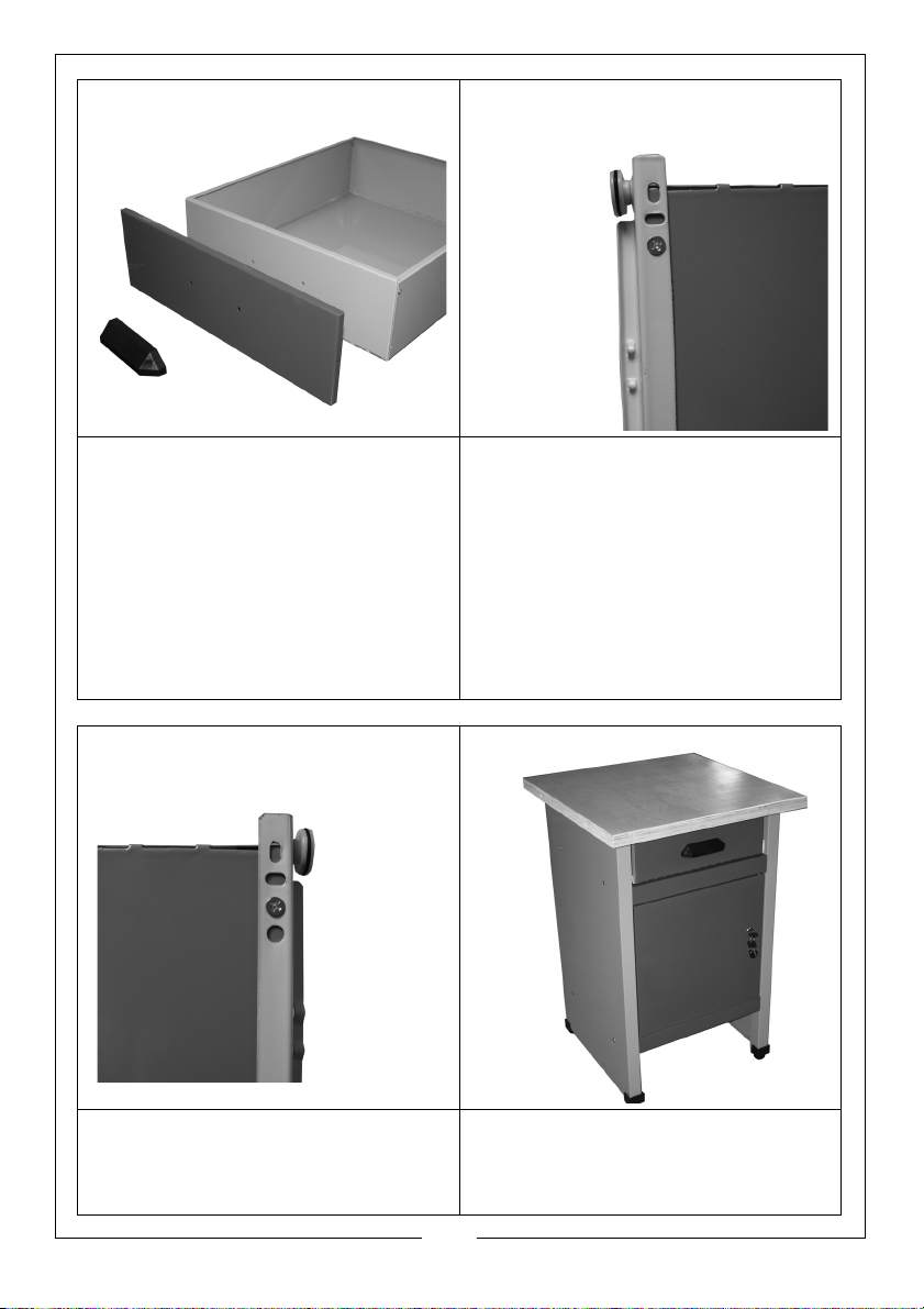
21. Fit the red drawer front (11) in
Viewed from below
Viewed from below
place and attach the handle
(10) to the drawer using the 2
screw supplied.
22. The drawer runners are marked
(DR and DL), and must be fitted
to the correct side of the drawer
when viewed from the front and
above the drawer, using the
small machine screws and nuts
23. The right hand runner (DR) must
be fitted as shown, note the
runner overhangs the rear of the
drawer slightly.
24. The left hand runner (DL) must be
fitted as shown, note the runner
overhangs the rear of the drawer
slightly.
25. Insert the drawer into the
workbench.
26. Fit the feet (7) to the workbench.
7
Parts & Service: 020 8988 7400 / E-mail: [email protected] or [email protected]
Page 8

 Loading...