

Page 1

3 DOOR LOCKABLE WALL CABINET
MODEL NO: CWC114
PART NO: 7642005
ASSEMBLY
INSTRUCTIONS
ORIGINAL INSTRUCTIONS GC 0421- rev 2
Page 2

INTRODUCTION
Thank you for purchasing this CLARKE product.
Before attempting to use this product, please read this manual thoroughly and
follow the instructions carefully. In doing so you will ensure the safety of yourself
and that of others around you, and you can look forward to your purchase
giving you long and satisfactory service.
GUARANTEE
This product is guaranteed against faulty manufacture for a period of 12
months from the date of purchase. Please keep your receipt which will be
required as proof of purchase.
This guarantee is invalid if the product is found to have been abused or
tampered with in any way, or not used for the purpose for which it was
intended.
Faulty goods should be returned to their place of purchase, no product can
be returned to us without prior permission.
This guarantee does not affect your statutory rights.
SPECIFICATIONS
Dimensions (w x d x h) 1140 x 190 x 600 mm
Weight 19.5 kg
Maximum Load Per Shelf 5 kg
Maximum Load Total 40 kg
2
Parts & Service: 020 8988 7400 / E-mail: [email protected] or [email protected]
Page 3
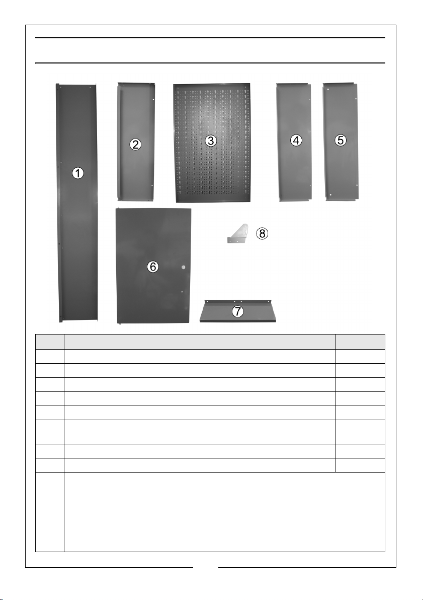
WHATS SUPPLIED
No Description Qty
1 Top/Bottom Panel 2
2 Side Panels 2
3Rear Panel 3
4Left Divider Panel 1
5 Right Divider Panel 1
6 Door (the centre door has a tool rack on the inside and will only fit
in the centre position)
7Shelf 4
8 Wall Hanging Brackets 2
9 Fixings kit (not shown) Includes
• 32 x M5x10 round head bolt set (bolt, washer, nut)
• 3 x M5x8 round head bolt set (bolt, washer, nut)
• 2 x M5x45 self tapping screw and rawl plug
• 3 Door Knobs
• 3 Lock Assemblies and Keys
3
3
Parts & Service: 020 8988 7400 / E-mail: [email protected] or [email protected]
Page 4

ASSEMBLY
1. Place the left divider between
two rear panels as shown.
3. Place the right divider against
the right panel as shown.
2. Use the fixings (nuts, bolts and
washers) supplied, to secure in
place.
4. Place the final rear panel
against the right divider and use
the fixings (nuts, bolts and
washers) supplied to secure in
place.
4
Parts & Service: 020 8988 7400 / E-mail: [email protected] or [email protected]
Page 5

5. Make sure that the left and right
dividers are orientated as
shown above.
6. Place the top panel in place
and use the fixings (nuts, bolts
and washers) supplied to
secure in place.
7. Repeat this with the bottom
and two side panels.
• Do not tighten fully at this stage.
8. Lift the top slightly and insert the
9. Fully tighten all fixings.
doors as shown.
• The hinge pins on the door must
be inserted into the holes in the
top and bottom panels.
5
Parts & Service: 020 8988 7400 / E-mail: [email protected] or [email protected]
Page 6
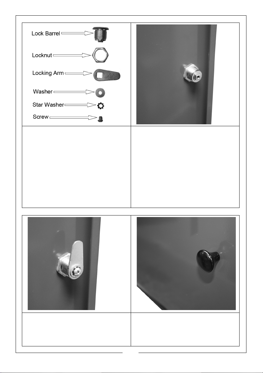
10. Place the key in the lock and
turn it so that the window on the
front of the lock turns green.
11. Remove the screw and star
washer from the rear of the
lock.
12. Remove the washer and
locking arm.
13. Remove the locknut from the
lock barrel.
14. Insert the lock barrel (with the
green window at the top)
through the door and secure
using the locknut as shown.
15. Replace the locking arm and
washer and secure using the
star washer and screw.
16. Check the lock and if necessary
adjust the orientation of the
locking arm.
17. Fit the door knob.
6
Parts & Service: 020 8988 7400 / E-mail: [email protected] or [email protected]
Page 7

18. Place the shelves into position
and secure using the fixings
supplied.
19. The rear panel can be used in
combination with tool hooks
(sold separately).
20. Place the tool hooks onto the
rear panel .
21. A combination of shelves and
tools is also possible.
22. Fit the wall hanging bracket as
shown (one on each side).
23. Fix the cabinet to the wall using
suitable screws (2” minimum)
and use rawl plugs suitable for
the wall being fixed to.
7
Parts & Service: 020 8988 7400 / E-mail: [email protected] or [email protected]
Page 8

 Loading...