

Page 1
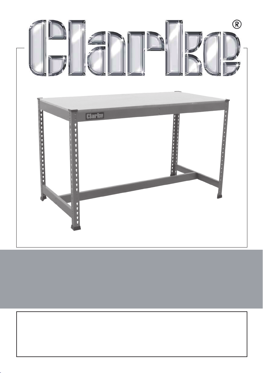
Heavy Duty Workbench
Model: CWB1530
Part No: 7637820
ASSEMBLY INSTRUCTIONS
GC10/12
Page 2
INTRODUCTION
Thank you for purchasing this CLARKE product. Before assembling the
workbench, be sure to read these instructions thoroughly. In doing so you will
ensure the safety of yourself and of others around you, and you can look
forward to the product giving you long and satisfactory service.
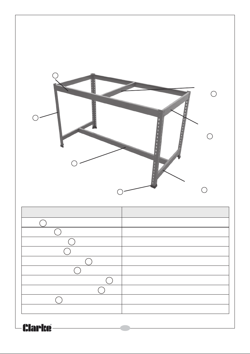
CONTENTS
Long Beam
A
Post
Centre Support
E
D
Plastic Foot
A
Posts (917mm long)
Plastic Feet
Plastic Post Caps
Centre Support
Long Beams (with holes)
Shelf Support Beam
B
C
D
E
F
Upper End Beams (without holes)
Lower End Beams (with holes)
MDF Board
Safe Working Load
I
Shelf Support
Beam
F
Upper End
Beam
G
Lower End
Beam
B
H
CWB1530 (with T-bar)
4
4
4
1
2
1
G
H
300kg (top shelf)
2
2
1
2
Parts & Service: 020 8988 7400/E-mail:[email protected] or [email protected]
Page 3
ASSEMBLY
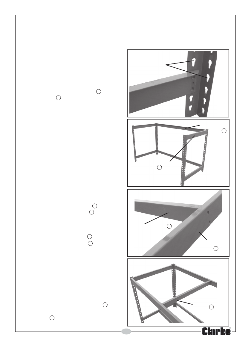
The tabs of the beams will often enter the slots fully using just firm hand pressure
but if they are too tight, you may require a rubber mallet or hammer
to assist. If so, always use a cloth to
protect the product paint finish.
1. Decide how high you want the tbar to be, relative to the floor.
FIG 1
Slots
2. Fit the upper end beams between
two posts as shown in Fig 1.
A
G
gently,• Only use the mallet to tap
ensuring the tabs of the beams
are in line with the slots in the posts.
• When using a hammer or mallet,
always strike the edge closest to
the post and protect the paint with
a cloth.
3. Repeat this again for the other
end of the assembly, making sure
that the corresponding end
beam is at the same height.
4. Now fit the long beams to match
the upper end beams as shown
E
G
in Fig 2.
5. Fit the centre support between
the lower end beams to provide
D
H
a t-bar only as shown in Fig 3.
Note that the edge with the wider
flange should be installed
uppermost. (The face with open
edges should face the re
ar of the
unit).
6. Slot the shelf support beam
F
between the front/rear long
beams shown in Fig 4.
E
Upper End
Beam
G
FIG 2
Centre Support
FIG 3
FIG 4
Long Beam
E
D
Lower
End
Beam
H
Shelf Support
F
Beam
3
Parts & Service: 020 8988 7400/E-mail:[email protected] or [email protected]
Page 4
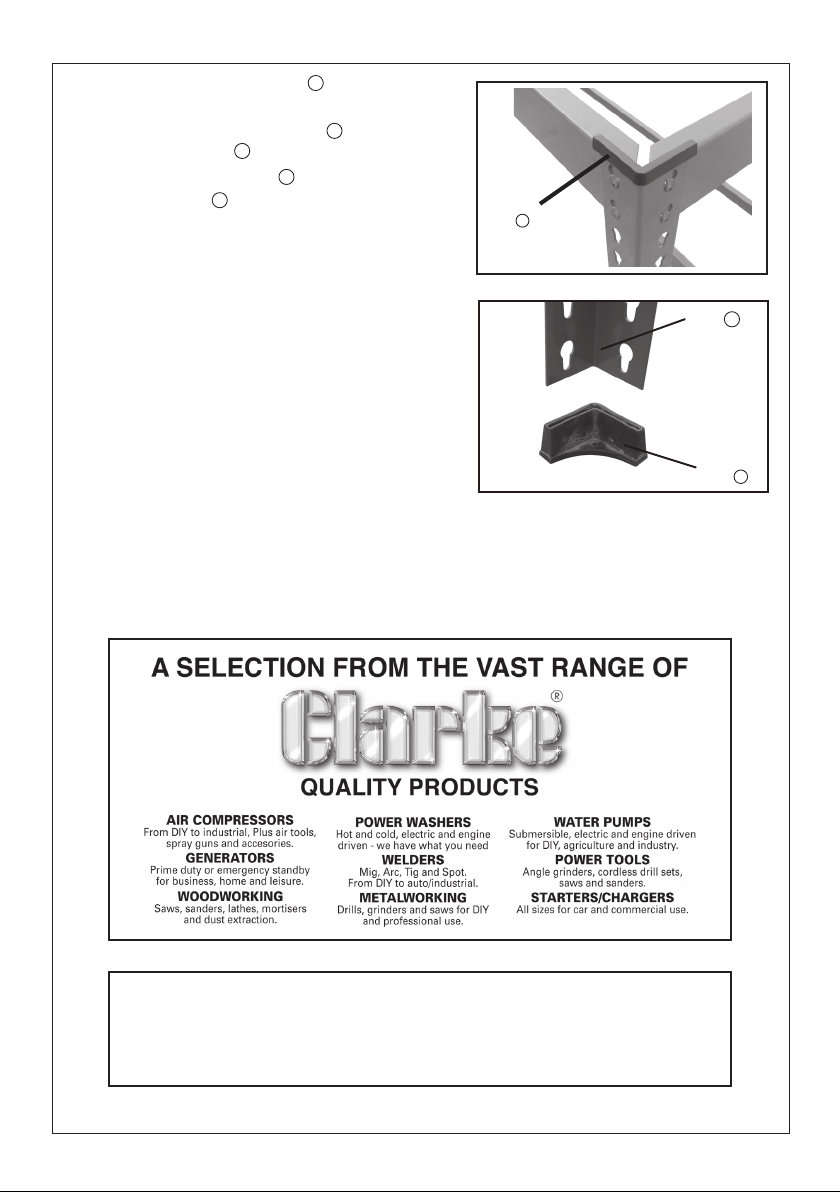
7. Place the MDF board on the
I
top shelf.
8. Fit the plastic post caps to top
of each post as shown in Fig 5.
A
9. Fix the plastic foot to end of
each post as in Fig 6.
A
SAFETY ADVICE
• Always distribute your loads evenly
C
B
Plastic
Post
cap
FIG 5
C
where possible.
GUARANTEE
This CLARKE product is guaranteed against
faulty manufacture for a period of 12 months
from the date of purchase. Please keep your
receipt as proof of purchase. This guarantee
is invalid if the product is found to have been
abused or tampered with in any way, or not
used for its intended purpose.
Faulty goods should be returned to their place of purchase, no product can
be returned to us without prior permission.
This guarantee does not effect your statutory rights.
FIG 6
Post
Plastic
Foot
A
B
Parts & Service: 0208 988 7400
E-mail: [email protected] or [email protected]
Clarke International Hemnall Street, Epping, Essex CM16 4LG
 Loading...