

Page 1
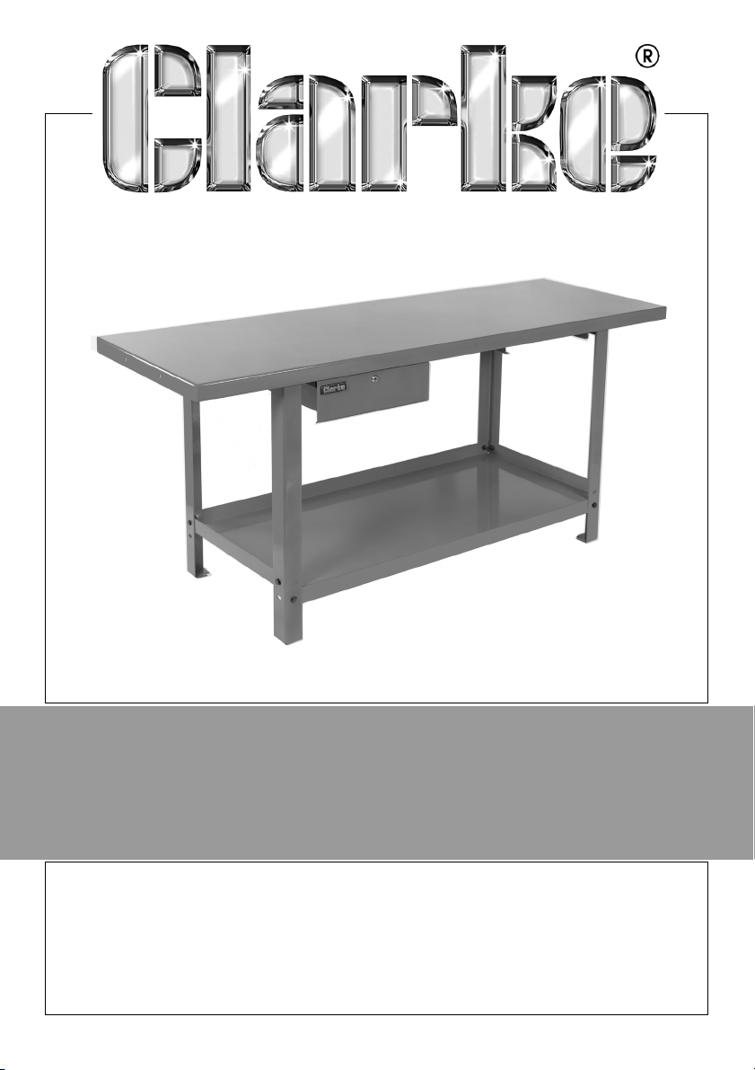
PRODUCTION WORKBENCH WITH DRAWER
MODEL NO: CWB2001P
PART NO: 7637809
ASSEMBLY INSTRUCTIONS
ORIGINAL INSTRUCTIONS GC0919 - ISS1
Page 2
SPECIFICATIONS
CWB2001P
Dimensions (w x d x h) mm 2000 x 650 x 865
Weight 68 kg
Maximum Load (table top) 300 kg
Maximum Load in Drawer 30 kg
Maximum Load (shelf) 80 kg
Maximum Load (CD3WB 3- drawer unit-sold separately) 90 kg
SAFETY PRECAUTIONS
ALWAYS seek assistance when lifting heavy items.
ALWAYS keep children and animals away from tools and work areas.
ALWAYS keep work area clean and free from oil spills etc.
ALWAYS wear protective footwear when assembling the workbench.
ASSEMBLY
Thank you for purchasing this CLARKE product. Please read and follow the
instructions carefully. Unpack your workbench and check to ensure that no
damage was suffered during transit. Should any damage be apparent you
should contact your CLARKE dealer immediately.
The kit comprises the workbench top, lower tray and four legs with 16xM8 bolts
with nuts and flat washers, the drawer, backstops and drawer runners with M6
screws. Position multiple units to create a run of benches for industrial use.
The workbench is best assembled
with the help of an assistant.
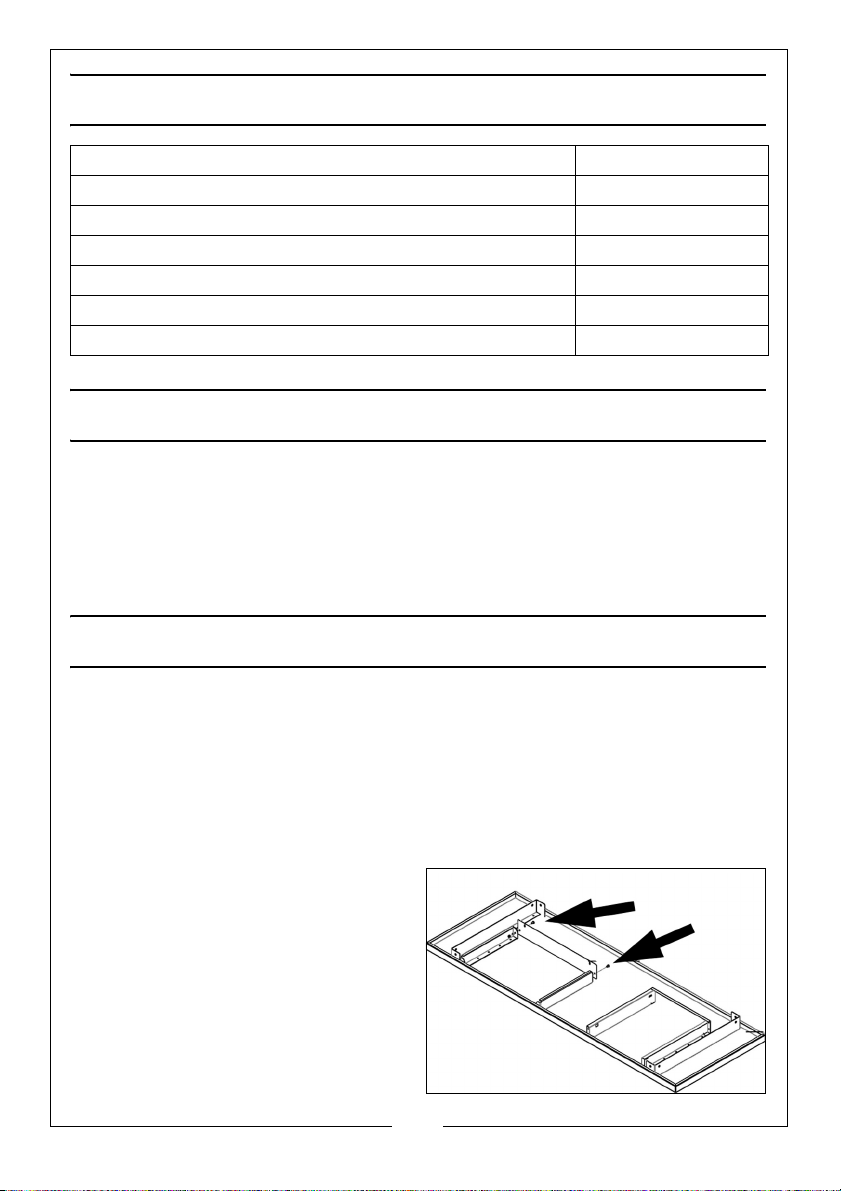
1. Rest the workbench top upside
down on a soft, protective surface
and fit the drawer backstops to the
base using the 4 x M6 screws,
washers and bolts. Use with a
CD3WB 3-drawer unit only.
2. At each of the rear mountings,
attach a leg, with the foot pad
2
Parts & Service: 020 8988 7400 / E-mail: [email protected] or [email protected]
Page 3
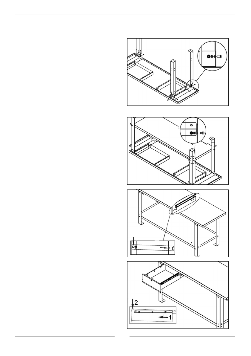
downwards using two M8 bolts with each leg, ensuring a flat washer is used
with the nut. Nip up the nuts - DO NOT fully tighten.
3. Attach the front legs in a similar
manner using M8 bolts with nuts
and flat washers. DO NOT fully
tighten.
4. With the help of an assistant,
position the shelf between the legs,
and bolt it to the legs using M8 bolts
with nuts and flat washers. DO NOT
fully tighten the nuts.
• NOTE The tray has an upstand at
the back only.
5. Turn the workbench on to its feet
and shake it vigorously to ensure it
is completely stable and resting
evenly on all four legs, then fully
tighten all nuts.
6. Fit the drawer runners to their
locations on the workbench frame
by engaging the tabs with the slots.
7. Slot the drawer into place in the
runners.
8. If a CD3WB 3-drawer unit is
purchased, this can be slotted into
place on the spare runners.
3
Parts & Service: 020 8988 7400 / E-mail: [email protected] or [email protected]
Page 4

 Loading...