

Page 1
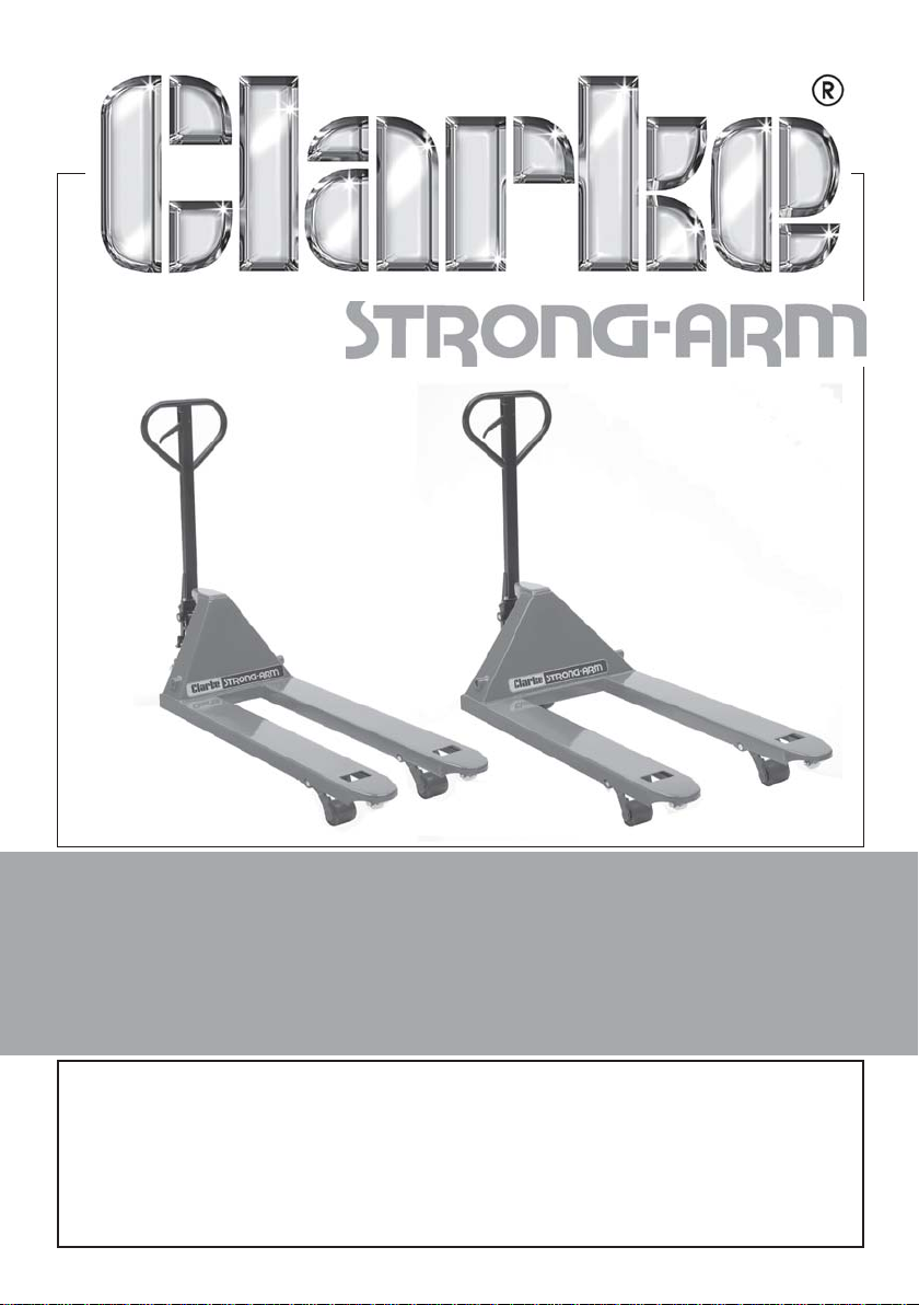
HYDRAULIC PALLET TRUCK
Models; PT550C & PT685C
Part Nos 7630172 & 7630177
OPERATING & MAINTENANCE
INSTRUCTIONS
GC05/12
Page 2
INTRODUCTION
Thank you for purchasing this CLARKE Pallet Truck.
Before attempting to use the product, it is essential that you read this manual
thoroughly and carefully follow all instructions given. In doing so you will
ensure the safety of yourself and that of others around you, and you can also
look forward to the product giving you long and satisfactory service.
CONTENTS
1 x Pallet Truck Assembly
1 x Detachable Handle
1 x Allen Key
1 x Owners Manual (this document)
GUARANTEE
This CLARKE product is guaranteed against faulty manufacture for a period of
12 months from the date of purchase. Please keep your receipt as proof of
purchase.
This guarantee is invalid if the product is found to have been abused or
tampered with in any way, or not used for its intended purpose.
Faulty goods should be returned to their place of purchase, no product can
be returned to us without prior permission.
This guarantee does not effect your statutory rights.
ENVIRONMENTAL PROTECTION
Do not dispose of this product or its packaging with general household waste. All tools, accessories and packaging should be sorted,
taken to a recycling centre and disposed of appropriately.
To avoid pollution due to leakage, the user should provide some absorbent
materials to capture any escape of oil during refilling of the hydraulic
mechanism. Such materials should then be disposed of appropriately.
2
Parts & Service: 020 8988 7400/E-mail:[email protected] or [email protected]
Page 3
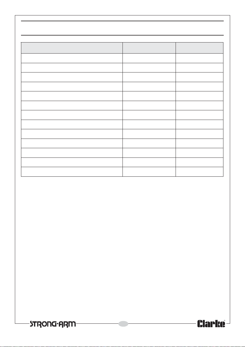
TECHNICAL SPECIFICATION
erutaeF C055TP C586TP
yticapacmumixaMgk0002gk0002
)eldnahcxe(mm)hxwxl(snoisnemiD544x055x0051544x586x0051
thgieWgk5.76gk17
ffoedistuoothtdiWmm055mm586
skro
htgnelkroFmm0511mm0011
htdiwkroFmm061mm061
ssenkcihtkroFmm06mm06
skrofneewtebpaGmm502mm
snoitpoyrtnE42
dnuorgmorfthgiehkrofniMmm57mm57
dnuorgmorfthgiehkrofxaMmm091mm091
ezisrellordaoLmm07x07mm07x07
skrofyllufesiarotsnoitcaforebmuN2131
Please note that the details and specifications contained herein, are correct at the
time of going to print. However, CLARKE International reserve the right to change
specifications at any time without prior notice.
563
3
Parts & Service: 020 8988 7400/E-mail:[email protected] or [email protected]
Page 4

SAFETY PRECAUTIONS
1. Keep the work area tidy & well lit and keep children and bystanders away
from the work area.
2. Never carry out any alterations or modifications to the pallet truck.
3. Do not exceed the stated capacity of the truck. Refer to the technical
specifications above and the labelling on the truck. Overloading may
cause the truck to fail.
4. Load the truck evenly with the centre of gravity of the load over the
centre of the forks. Never stand on the forks.
5. Do not use on rough terrain. The pallet truck is designed for use on smooth
flooring only. Do not bounce the truck over rough ground, or down curbs
etc. Use ramps wherever possible.
6. Do not move unstable or loosely stacked loads. Use special care when
moving long, tall or wide loads or transporting a load which may impair
your view.
7. Never position any part of your body under the lifting mechanism or under
the forks. Do not transport passengers on the truck.
8. Do not operate a pallet truck until you have checked its condition, giving
special attention to the wheels, handle, forks and lift/lower controls.
9. Never use the pallet truck on a gradient if the load is too heavy to be
easily handled by the operator. The truck should not be used by operators
who are not physically capable of handling the loaded pallet truck.
10. Do not use if wheels or castors are damaged. Have them replaced
immediately.
11. When not in use, always ensure the truck is left where it is not hazard to
others. Never leave the truck on a gradient without first securely chocking
the wheels.
Please keep these instructions in a safe place for future reference.
4
Parts & Service: 020 8988 7400/E-mail:[email protected] or [email protected]
Page 5
ASSEMBLY
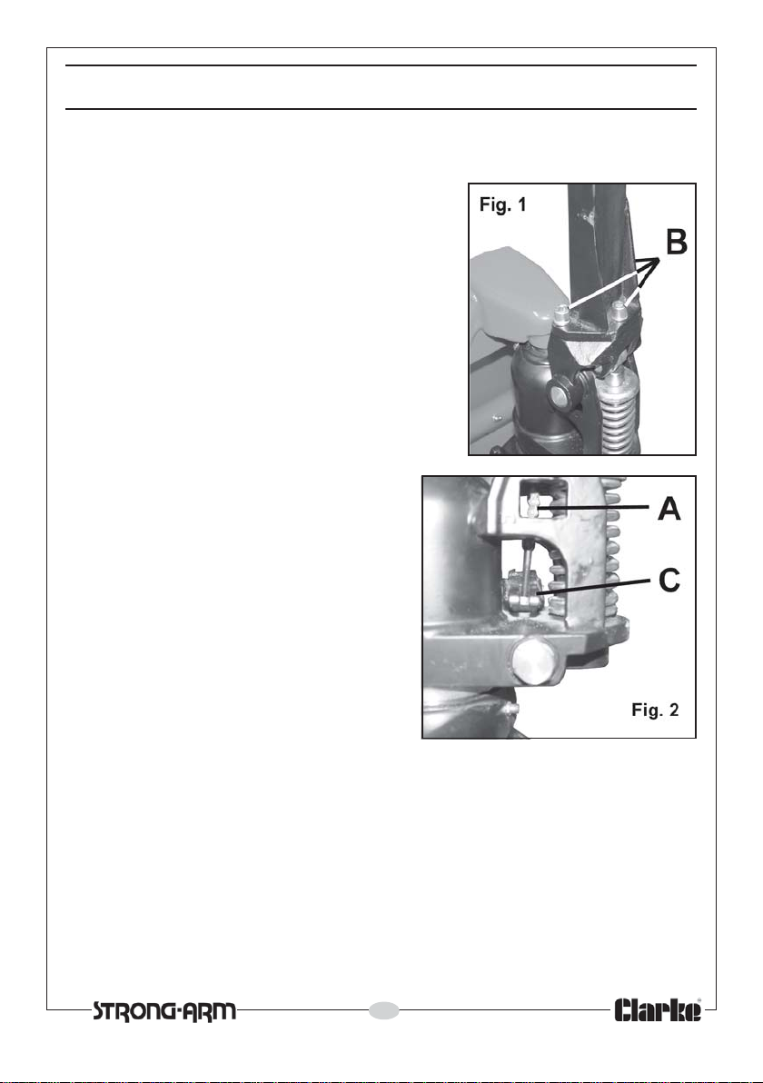
After unpacking, it is necessary to attach the truck handle assembly as
follows. (Part numbers refer to the list/diagrams on pages 10-13).
1. Take the handle assembly and lower the
end of the chain ‘A’, through the hole in the
pump body, so that it emerges at the
bottom of the housing.
2. Secure the truck handle to the base bracket
with the three socket-headed screws, ‘B’ ,
as in Fig 1, tightening them with the
hexagon key provided.
3. Release the screw adjuster (154) in Fig
4, in order to raise the end of the
forked lever, shown at ‘C’, Fig. 2, and
slide the threaded rod/locknut
attached to the end of the chain, ‘A’
between the forks, so that the locknut,
screwed on to the threaded rod,
locates behind the claws on the
underside of the forks. Release the
forked lever and screw the adjuster
(154) back in to remove any slack
from the mechanism.
Your pallet truck is now fully assembled, however, before use it is IMPORTANT
to check the following adjustments.
5
Parts & Service: 020 8988 7400/E-mail:[email protected] or [email protected]
Page 6
ADJUSTMENT
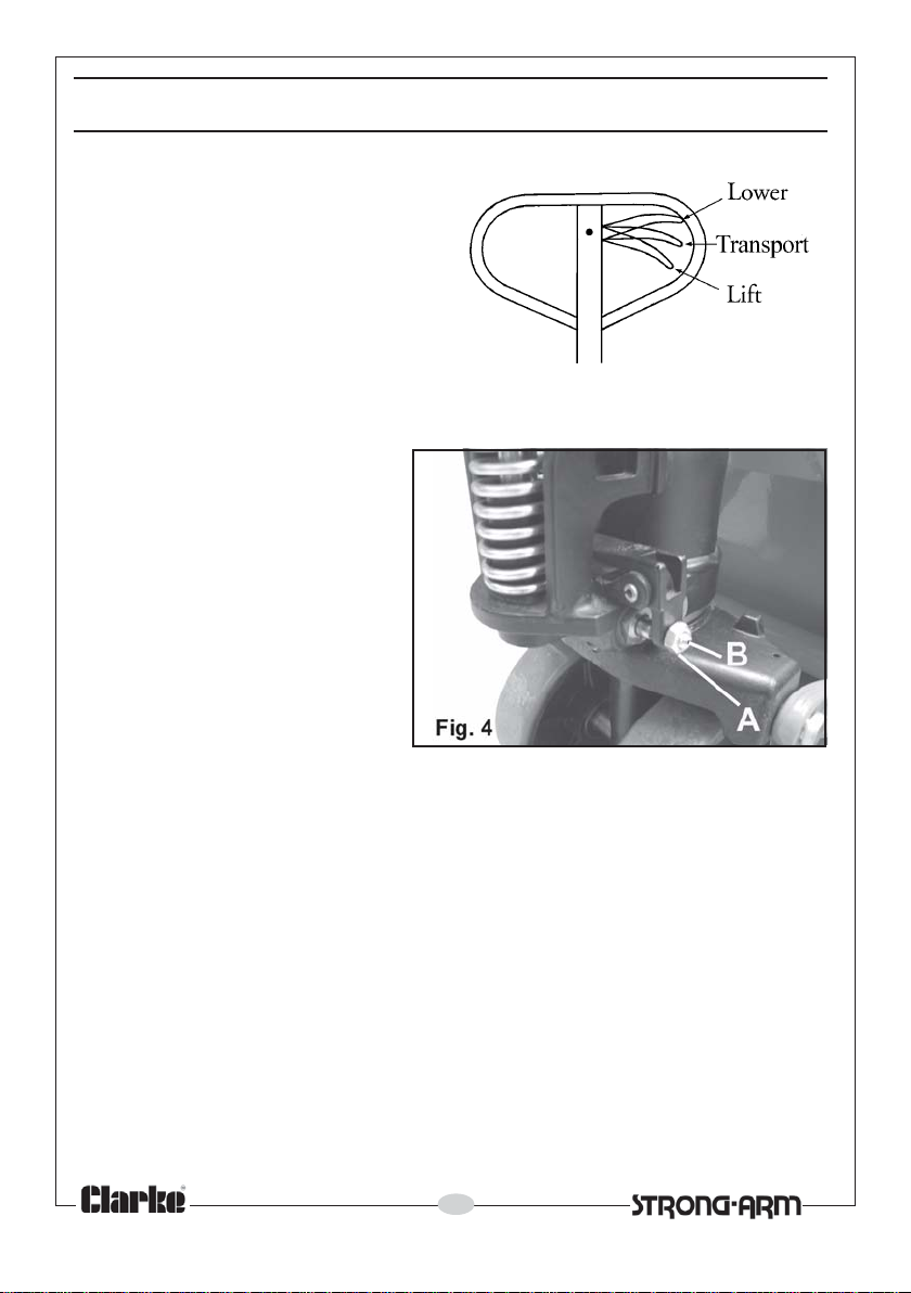
The control lever has three positions
shown in Fig 3 and indicated by the
label on the handle.
With the lever pulled to the upper
position, the forks will lower.
The middle position allows the load
to be transported.
The lower position will cause the forks
to lift when the handle is pumped.
1. Set the control lever to its
lowest position (i.e. Lever in its
LIFT position).
2. If the forks rise while pumping
in the TRANSPORT position,
release the locking nut (A)
and turn the adjusting screw
(B) clockwise until the
pumping action does not raise
the forks and they remain in
position in the TRANSPORT
position.
3. If the forks descend while
pumping in the TRANSPORT
position, turn the adjusting screw (154) anti-clockwise until the forks do not
lower.
4. If the forks do not descend when the control handle is in the LOWER
position, turn the adjusting screw (B) clockwise until raising the control
handle lowers the forks. Check it’s operation in the TRANSPORT position.
5. If the forks do not elevate while pumping in the LIFT position,turn the
adjusting screw (B) anti-clockwise until the forks raise while pumping in the
LIFT position. Finally check the operation in the LOWER and TRANSPORT
positions.
Fig. 3
6
Parts & Service: 020 8988 7400/E-mail:[email protected] or [email protected]
Page 7

OPERATION
Before using the pallet truck always read the safety instructions in this manual
and the labelling on the product. The rated capacity of the truck assumes an
evenly distributed load with it’s centre being at the halfway point along the
length of the forks.
With the forks in the lowest position, manoeuvre the truck so that it is adjacent
to the pallet. Ensure the length of the forks match the length of the pallet.
Always position the pallet truck carefully, ensuring the load is centred about
the forks and is completely stable. Ensure there is no obstruction before raising
the load, or that the load cannot foul the truck mechanism when raised.
Lower the forks to the lowest height when the truck is not being used.
When lowering the truck with the forks loaded, pull the control lever up
carefully and gradually so that the load descends under complete control.
7
Parts & Service: 020 8988 7400/E-mail:[email protected] or [email protected]
Page 8

MAINTENANCE
Whilst the pallet truck requires very little maintenance, the following care can
be expected.
DAILY CHECK
Before use, check that there are no foreign bodies such as threads or rag to
jam the wheels. Always leave the forks in the lowered position when work is
over for the day.
CHECKING THE OIL
Check the oil level every six months by topping up if necessary at the filler
plug (144). The capacity is approximately 0.3 litres. The recommended type is
L-HV46 Hydraulic oil, provided the truck is not to be used outside the
temperature range of -20°C to +40°C.
BLEEDING AIR FROM THE PUMP UNIT
If the pallet truck has to be transported over any distance or been
overturned at any time, air may have permeated the hydraulic oil. This will
make it impossible to raise the forks under any load when pumping.
To bleed off the air, move the control handle (308) to the lower position, then
move the handle (310) up and down several times.
GREASING
Moving parts can be lubricated with motor oil or grease. After prolonged use,
the pivoting action of the steering wheel assembly may become stiff. In this
case, a shot of grease via the grease nipples (118 and 202) will restore
smooth movement.
For parts & servicing, please contact your nearest dealer, or
CLARKE International, on one of the following numbers.
PARTS & SERVICE TEL: 020 8988 7400
PARTS & SERVICE FAX: 020 8558 3622
or e-mail as follows:
PARTS: [email protected]
SERVICE: [email protected]
8
Parts & Service: 020 8988 7400/E-mail:[email protected] or [email protected]
Page 9

TROUBLESHOOTING
melborP esuaC noitcA
otesiartonnacskroF
.thgiehmumixameht
.esiartonlliwskroFliocil
ebtonnacskroF
.derewol
aelro
.rucco
dA
.gnika
elsimsinahceMslaesdegamadronraWwenhtiwecalper&luahrevO
ehttubesiarskrofehT
.krow
tonlliwevlavesaeler
uardyhfokcaL
.thgitoot
.noitisoptcerroc
.desolcgnikcol
.stnenopmoc
detanimatnocsiliO
.lioehtnitneserpriA
.liociluardyhtneiciffusnI.liohtiwpupoT
eudneposievlavgnipmuP
ootgnieb)513(tunehtot
si)451(wercsehtrohgih
pmupro)101(dornotsiP
oteuddegamadsiydob
.edisenootgnin
otnotsipdesopxeehtfo
ehtro)513(tungnitsuj
ehtnitonsi)451(wercs
silioehtfonoitanimatnoC
morfevlavehtgnitneverp
ehtforaewrognikcarC
.lioehtpupoT
.lioehtegnahC
.)451(wercs
.ydobpmupeht
gnidaolrevo,gnidaolnevenu
noitisophgihnineebsahkroF
noisorrocrofhguonegnolrof
.)451(wercs
.strap
.lioehtweneR
ehtro)513(tunehttsujdA
.riaehtllepsidotlioehtdeelB
ro)101(dornoitsipecalpeR
ehtniskrofehtpeeksyawlA
tehtnehwnoitisoptsewol
kcur
ehtetacirbuL.esunitonsi
.liohtiwdornotsip
ehtro)513(tunehttsujdA
aewrofstraptcepsnI
&r
.yrassecensaecalper
serpriA
Parts & Service: 020 8988 7400/E-mail:[email protected] or [email protected]
.lioehtnitne
.degamadronrowslaesliO
ehtro)513(tungnitsujdA
ehtnitonsi)451(wercs
.noitisoptcerroc
9
.slaes
ehttsujdA
.)451(wercsro)513(
.riaehtlepxeotmetsysdeelB
degamadronrowecalpeR
tunfonoitisop
Page 10
PARTS LIST & DIAGRAM - PUMP
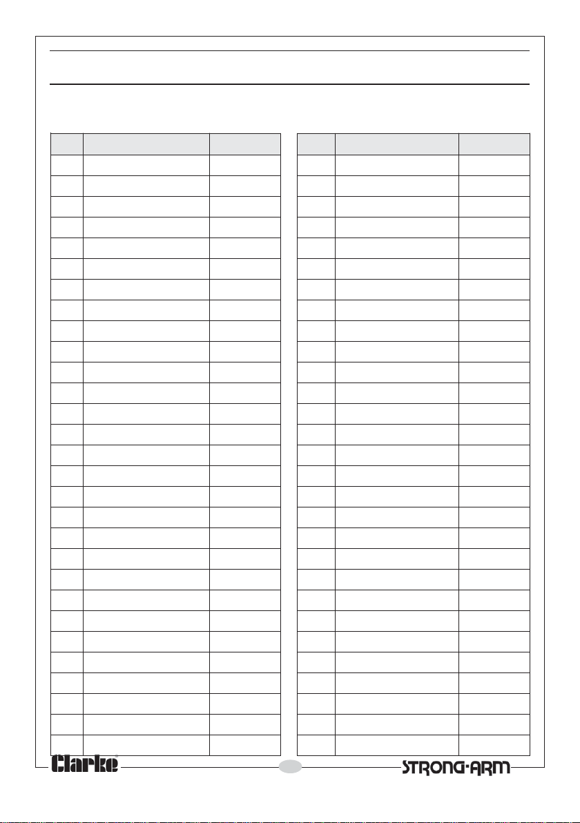
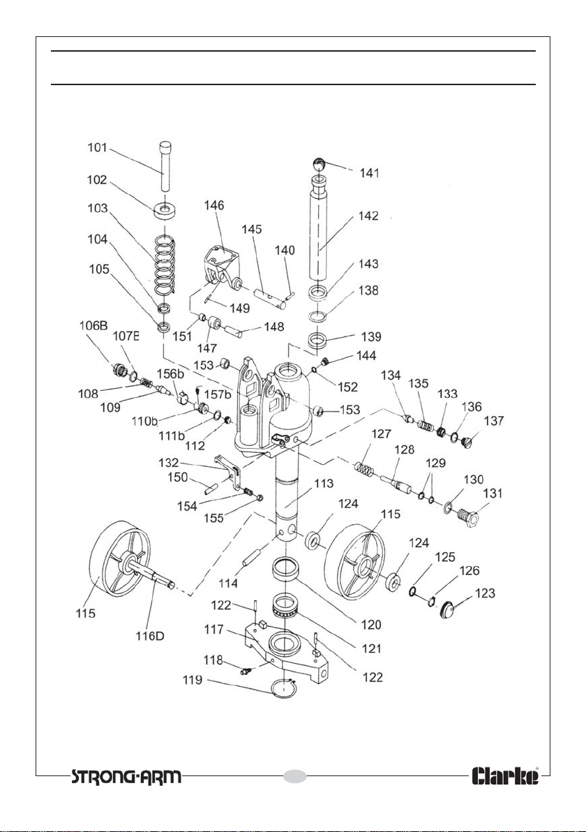
When requesting spare parts, quote ref: ZNEPT 550C or 685C according to the
model, followed by the suffix 001-onwards, and listed in the table.
oN noitpircseD feRtraP feR noitpircseD feRtraP
101
201rehsaW200131paCgniniateR130
301gnirpS300231tekcarB230
401gniRtsuD400331tl
501laeS500431eldnipSevlaVytefaS430
B601paCgniniateR600531gnirpS530
B701gnir-O700631gnir-O630
801gnirpS800731we
901eldnipSevlaVpmuP900831gnir-O830
B011taeSevlaV010931laeS-Y930
B111gnir-O110041niPlloR040
211llaBleetS210141llaBleetS1
311gnitsaCesaBpmuP310241doRnotsiP240
411niPlloR410341gniRtsuD340
511)riap(leehWgnireetS510441wercSrelliF440
D611tfahSl
711etalPtsurhT710641tekcarB640
811elppiNesaerG810741relloRerusserP740
911pilcriC910841tfahS840
1revoCgniraeB020941niPlloR940
02
121gniraeB120051niPlloR050
221niPlloR220151gnihsuB150
321)riap(revoCtsuD320251rehsaWlaeS250
421)
521)riap(rehsaW520451wercSgnitsujdA450
621)riap(pilcriC620551tuN550
721gnirpS720B651eveelS650
21niPekirtS820B751wercSburG750
8
921)riap(sgnir-O920
Parts & Service: 020 8988 7400/E-mail:[email protected] or [email protected]
doRnotsiPpmuP100031rehsaWgnilaeS030
oBgnitsujdA330
rcS730
40
eehWgnireetS610541tfahS540
riap(gniraeB420351gnihsuB350
10
Page 11
PARTS LIST & DIAGRAM - PUMP
11
Parts & Service: 020 8988 7400/E-mail:[email protected] or [email protected]
Page 12
PARTS LIST & DIAGRAM - FORK FRAME
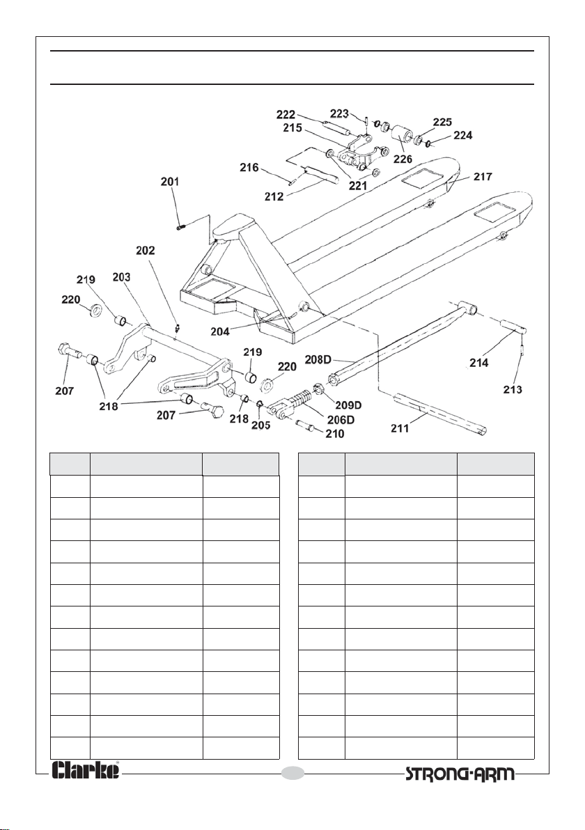
oN noitpircseD feRtraP oN noitpircseD
102
202elppiNesaerG550512mrArelloR
302mrApmuP650612niPlloR
402niPlloR750712emarFkr
502gniRgniniateR850812hsuBegniHtnorF
D602dnEkroF950912hsuBegniHraeR
702niPtnioJ060022rehsaW
D80
2doRhsuP160122rehsaW
D902tuN260222tfahSrelloR
012niPegniH360322niPlloR
112tfahStoviP460422rehsaW
212eldnipS56052
312niPlloR660622relloR
Parts & Service: 020 8988 7400/E-mail:[email protected] or [email protected]
wercS450412tfahStoviP
oFgnitfiL
2gniraeB
12
feRtraP
760
860
960
070
170
270
370
470
570
670
770
870
970
Page 13
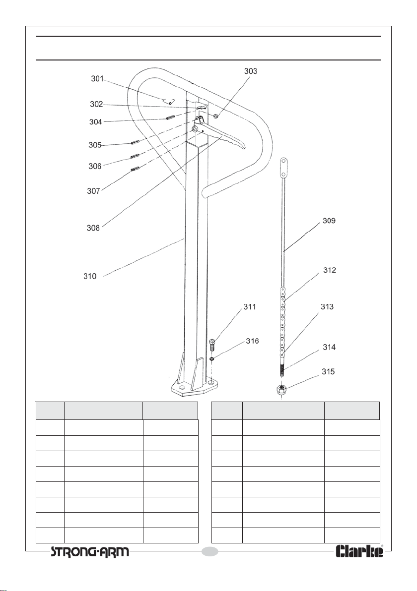
PARTS LIST & DIAGRAM - HANDLE
oN noitpircseD feRtraP oN noitpircseD feRtraP
103
203gnirpSedalB180013mrAeldnaH980
303relloR280113)3x(wercS090
403niPlloR380213niahC190
503niP
603niPlloR580413tloBgnitsujdA390
703niPlloR680513tuNgnitsujdA490
803eldnaHlortnoC780613)3x(rehsaWgnirpS590
Parts & Service: 020 8988 7400/E-mail:[email protected] or [email protected]
gnirpS080903doRwarD880
lloR480313niP290
13
Page 14
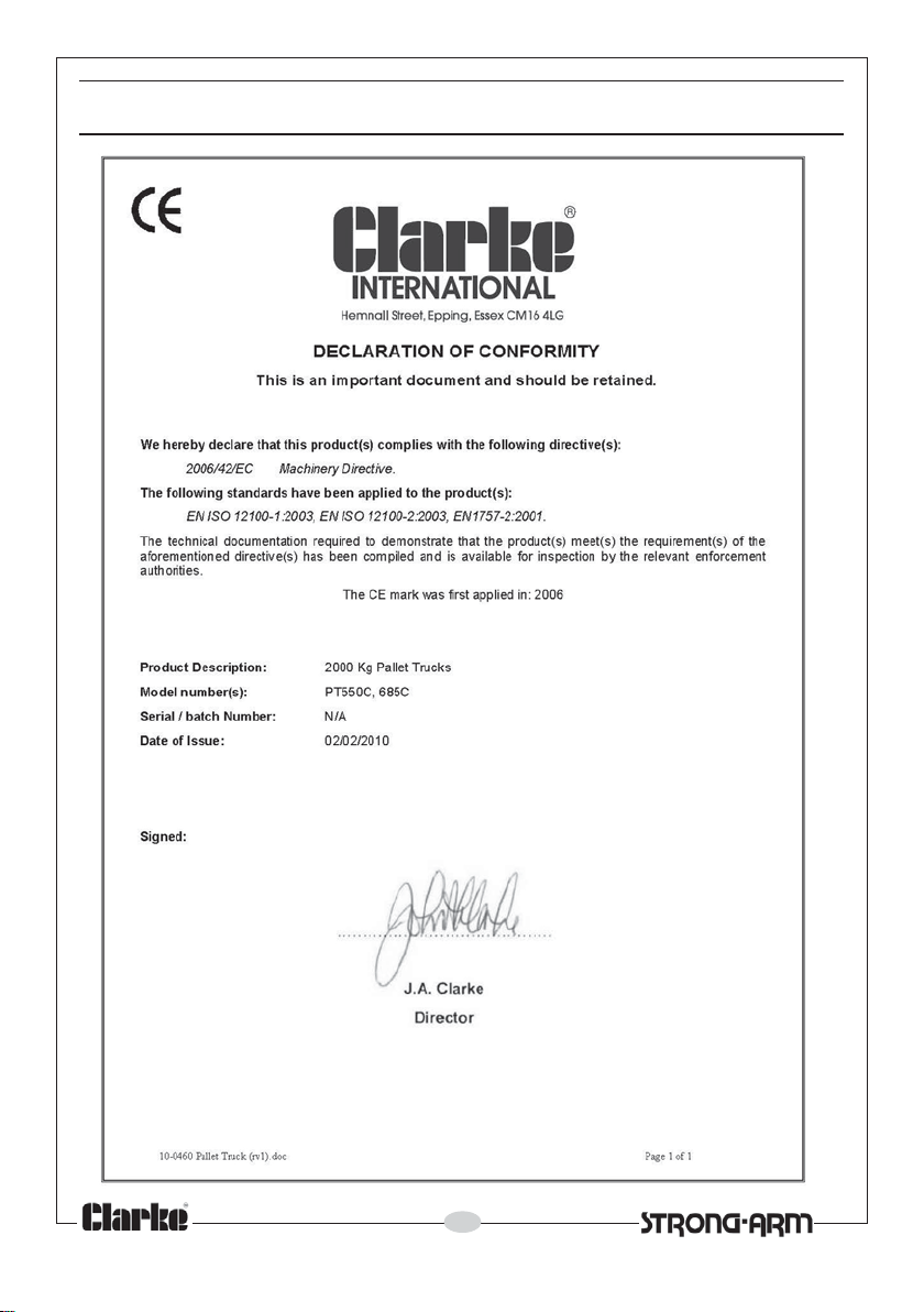
DECLARATION OF CONFORMITY
14
Parts & Service: 020 8988 7400/E-mail:[email protected] or [email protected]
Page 15

NOTES
__________________________________________________________________________
__________________________________________________________________________
__________________________________________________________________________
__________________________________________________________________________
__________________________________________________________________________
__________________________________________________________________________
__________________________________________________________________________
__________________________________________________________________________
__________________________________________________________________________
__________________________________________________________________________
__________________________________________________________________________
__________________________________________________________________________
__________________________________________________________________________
__________________________________________________________________________
15
Parts & Service: 020 8988 7400/E-mail:[email protected] or [email protected]
Page 16
 Loading...