

Page 1
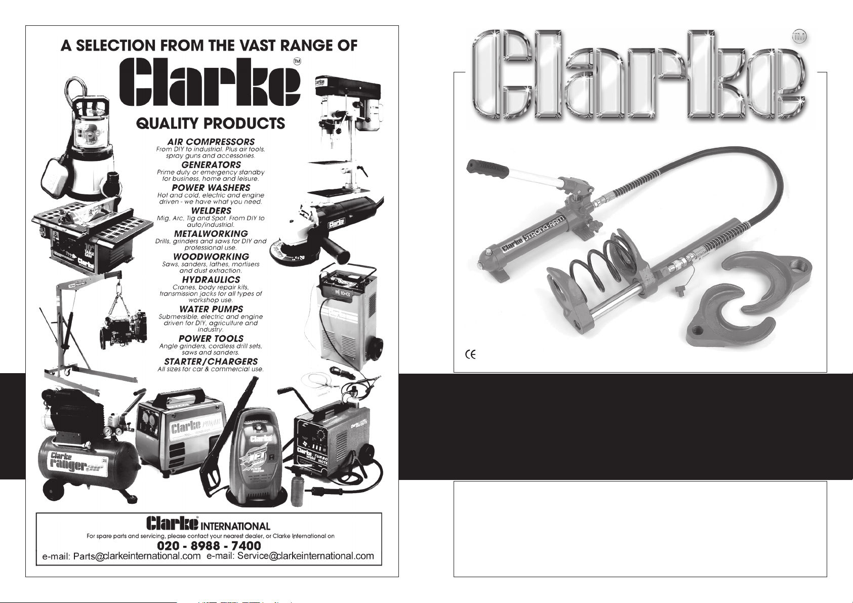
COIL SPRING COMPRESSOR
MODEL No: CSC1000
Part No: 7629005
OPERATING & MAINTENANCE
INSTRUCTIONS
0504©
Page 2
Thank you for purchasing this CLARKE Hydraulic Spring Compressor.
This product is designed and constructed for use with all types of spring shock
absorber from 78mm to 182mm in diameter.
Please read this leaflet thoroughly and follow the instructions carefully, in doing so
you will ensure the safety of yourself and that of others around you, and you can
look forward to the unit giving you long and satisfactory service.
Please note that this manual is an integral part of the Spring Compressor and must
always accompany it, even in the event of sale.
CLARKE International shall not be held liable to any damage to persons or
equipment due to improper or non-permitted use of the unit.
SPECIFICATIONS
Capacity (Max. compressive tensiom) ................. 1650lbs
Max. Extension ......................................................... 260mm
Fully Retracted Dimension ...................................... 100mm
Rod Travel ................................................................. 100mm
Weight ....................................................................... 23kg
GUARANTEE
This CLARKE product is guaranteed against faulty manufacture for a period
of 12 months from the date of purchase. Please keep your receipt as
proof of purchase. This guarantee is invalid if the product is found to have
been abused or tampered with in any way, or not used for the purpose
for which it was intended.
Faulty goods should be returned to their place of purchase, no product
can be returned to us without prior permission.
This guarantee does not effect your statutory rights.
SAFETY PRECAUTIONS
• Never tamper with the pump. The safety valve is calibrated and sealed at the
factory, do not attempt to change these settings.
• Use ONLY the recommended hydraulic oil.
• Never use the pump for any purpose other than that for which it is designed.
• Do not exceed the maximum working pressure. See Specifications
• Use only Spare Parts supplied by Clarke International. The use of parts other
than those supplied by Clarke International could be hazardous, or cause
damage to the equipment, and will invalidate the guarantee.
2
Parts List- PUMP
Item Description Qty Part No.
11 Rubber Handle 1 SNCSC100011
12 Handle 1 SNCSC100012
13 Actuator 1 SNCSC100013
14 Circlip 2 SNCSC100014
15 Pin 1 SNCSC100015
16 Pin 1 SNCSC100016
22 Oil Filter 1 SNCSC100022
23 Steel Ball 3 SNCSC100023
24 Coupler 1 SNCSC100024
25 Dust Cover 1 SNCSC100025
26 High Pressure Hose 1 SNCSC100026
27 Nut 1 SNCSC100027
28 O-Ring 1 SNCSC100028
29 Relief Valve Knob 1 SNCSC100029
31 O-Ring 1 SNCSC100031
32 Draw Rod 1 SNCSC100032
33 Oil Filter 1 SNCSC100033
34 O-Ring 1 SNCSC100034
35 Oil Reservoir 1 SNCSC100035
36 O-Ring 1 SNCSC100036
37 Valve Block 1 SNCSC100037
38 Oil Filler Screw 1 SNCSC100038
39 O-Ring 1 SNCSC100039
40 End Cover 1 SNCSC100040
41 Steel Ball 1 SNCSC100041
42 Steel Ball retainer 1 SNCSC100042
43 Adjuster Spring 1 SNCSC100043
44 Pressure Adjuster Screw 1 SNCSC100044
45 Stop Nut 1 SNCSC100045
46 Cover 1 SNCSC100046
47 Spring 1 SNCSC100047
48 O-Ring 1 SNCSC100048
52 Nut 1 SNCSC100052
53 O-Ring 1 SNCSC100053
54 O-ring 1 SNCSC100054
55 Plunger Seal 1 SNCSC100055
56 Plunger Housing 1 SNCSC100056
57 Plunger 1 SNCSC100057
59 O-Ring 1 SNCSC100059
7
Page 3
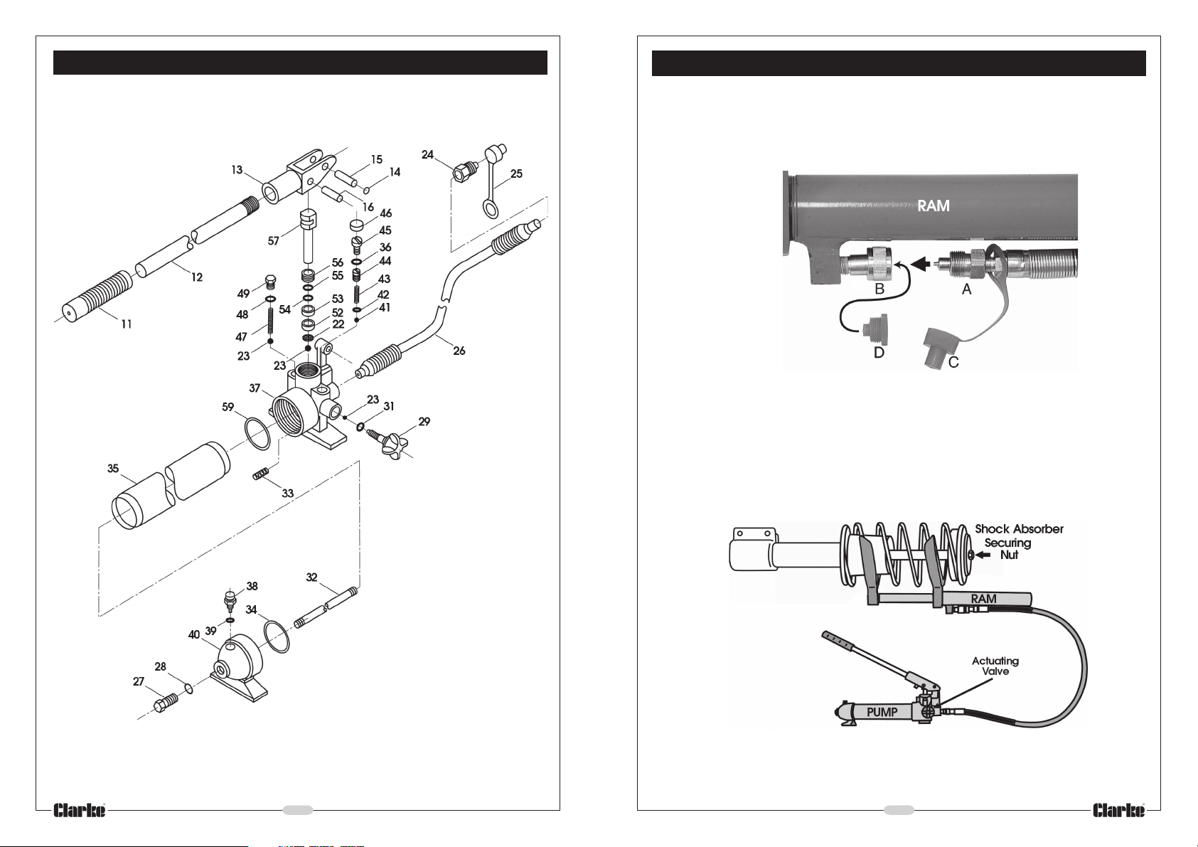
Parts - PUMP
ASSEMBLY AND OPERATION
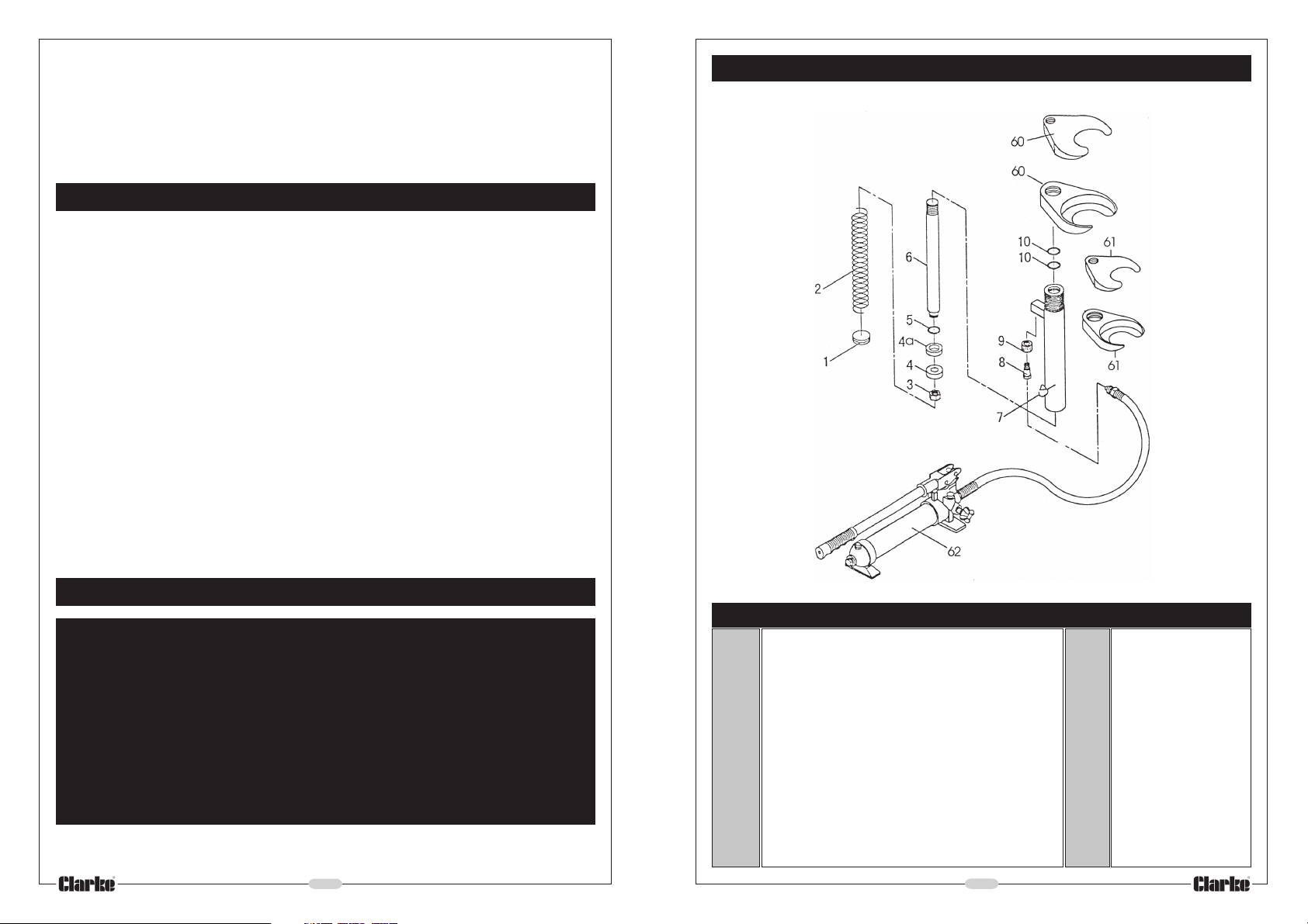
1. Remove the transit plugs (C Fig.1) from the hydraulic connector at the end of
the pump hose (A, Fig,1).
2. Remove the transit plugs (D Fig.1) from the adapter at the ram (B, Fig. 1)
3. Push the hose connector ‘A’ into the ram adapter ‘B’ and tighten the ring nut
by hand only.
4. Select the appropriate claws to suit the coil spring, and attach to the Ram.
The claws are not interchangeable. Ensure they are screwed on fully, with the
spring seats facing each other.
5. Turn the Actuating Valve knob (see Fig.2) fully clockwise.
6. Position the coil spring so that the coils bed into the claws fully. It may be
necessary to draw the claws together by pumping the pump handle a few
times in order to do so. Check to ensure the coils are seated neatly before
continuing to pump the handle, thereby compressing the spring.
Eventually, pressure on the shock absorber securing nut will be completely relieved,
when, at this point, the nut will turn easily. WARNING! DO NOT undo the nut until
this condition exists.
With the nut removed, the shock absorber may be withdrawn.
6
3
Page 4
Install the new shock absorber installed, and ensure the securing nut is tightened
according to manufacturers instructions before turning the actuator knob
anticlockwise so that the ram extends, allowing the coil spring to reassert so that
the complete assembly may be removed from the compressor.
MAINTENANCE
If performance begins to decline, bleed the pump as follows:.
1. Tighten ( turn clockwise) the actuator knob on the pump while the
pump hose is still attached to the main assembly.
2. Remove the oil filler cap, then pump the handle slowly to bleed air
from the system. Repeat until no air is expelled
3. Add clean, high quality hydraulic oil if necessary and then replace
the oil filler cap.
4. Test the pump by tightening the actuator knob and pump the handle.
The spring Compressor should operate satisfactorily. If it does not
performing properly, repeat the bleeding procedure.
Parts - RAM
PARTS AND SERVICE CONTACTS
For Spare Parts and Service, please contact your nearest dealer,
or CLARKE International, on one of the following numbers.
PARTS & SERVICE TEL: 020 8988 7400
PARTS & SERVICE FAX: 020 8558 3622
or e-mail as follows:
PARTS: [email protected]
SERVICE: [email protected]
4
Item Description Qty Part No.
1. Screw 1 SNCSC100001
2. Spring 2 SNCSC100002
3. Nut 1 SNCSC100003
4. Bushing 1 SNCSC100004
4a. Sealing Ring 1 SNCSC100004a
5. Retaining Ring 1 SNCSC100005
6. Piston Rod 1 SNCSC100006
7. Cylinder 1 SNCSC100007
8. Cylinder Screw 1 SNCSC100008
9. Connection Nut 1 SNCSC100009
10. O-Ring 2 SNCSC100010
60. Claw Set #1 (170mm) 1 SNCSC100060
61. Claw Set #2 (130mm) 1 SNCSC100061
62. Hand Pump 1 SNCSC100062
5
 Loading...