

Page 1
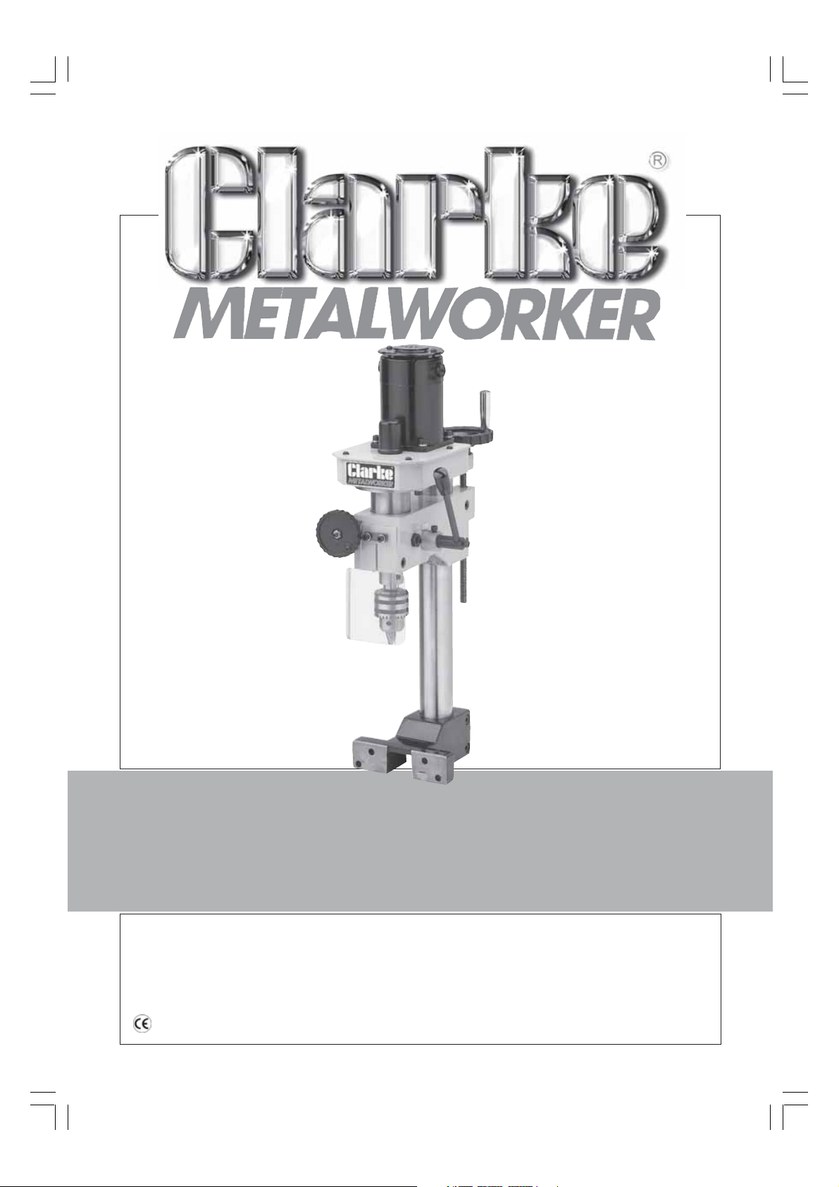
MILLING/DRILLING ATTACHMENT
MILLING/DRILLING ATTACHMENT
Model No.CL251MH
Part No. 7610741
OPERATING & MAINTENANCE
OPERATING & MAINTENANCE
INSTRUCTIONS
INSTRUCTIONS
1203
©
Page 2
© Copyright, CLARKE International. August 2003. All rights reserved
SPECIFICATIONS
Motor ................................................................................ 230V 50Hz 1ph
Power Rating.................................................................... 150W
Spindle Taper ................................................................... MT2
Spindle Speed.................................................................. 10-1300RPM
Max. Spindle Travel ......................................................... 30mm
Max. Dist. Chuck to Table............................................... 168mm
Dist. Column to Chuck Centre ....................................... 105mm
Overall Dimensions (WxDxH) .......................................... 220x410x575mm
Weight net ....................................................................... 18kg
2
Page 3
Thank you for purchasing this CLARKE - Micro Milling and Drilling machine attachment, designed for use
with model CL250M Variable Speed Metal Lathe
Before attempting to operate the machine, please read this instruction manual thoroughly, and follow
all directions carefully. By doing so you will ensure the safety of both yourself and others around you, and
at the same time, you should look forward to the Press giving you long and trouble free service.
GUARANTEE
This product is guaranteed against faults in manufacture for 12 months from date of purchase. Please
keep your receipt as proof of purchase.
This guarantee is invalid if the product has been found to have been abused or tampered with in any
way, or not used for the purpose for which it was intended. The reason for return must be clearly stated.
This guarantee does not affect your statutory rights.
TABLE OF CONTENTS
PAGE
Declaration of Conformity ............................................................................................. 2
Specifications ..................................................................................................................2
Safety Precautions .......................................................................................................... 4
Additional Safety Rules for Mill/Drills ............................................................................. 5
Electrical Connections ................................................................................................... 6
Preparation for Use ......................................................................................................... 7
Assembly .......................................................................................................................... 8
Operation ........................................................................................................................ 9
Maintenance ................................................................................................................. 11
Accessories .................................................................................................................... 12
Spare Parts and Service Contacts .............................................................................. 13
Parts Lists and Diagrams ......................................................................................... 14-15
3
Page 4

GENERAL SAFETY PRECAUTIONS
FOR OPERATING MACHINERY
WARNING
As with all machinery, there are certain hazards involved with their operation and
use. Exercising respect and caution will considerably lessen the risk of personal
injury. However, if normal safety precautions are overlooked, or ignored,
personal injury to the operator, or damage to property may result.
1. KNOW YOUR MACHINE. Read the manual carefully. Learn the machines applications
and limitations, as well as the specific potential hazards peculiar to it.
2. KEEP GUARDS IN PLACE and in working order.
3. EARTH ALL MACHINES. If the machine is equipped with three-pin plug, it should be
plugged into a three-pin electrical socket. Never remove the earth pin.
4. REMOVE ALL ADJUSTING KEYS AND WRENCHES. Before starting, form the habit of checking
to ensure that keys, wrenches and tools are removed from the machine.
5. KEEP WORK AREA CLEAN. Cluttered areas and benches invite accidents.
6. DON’T USE IN DANGEROUS ENVIRONMENT. Don’t use machinery in damp or wet locations,
or expose them to rain. Keep work area well lit.
7. MAKE WORKSHOP CHILDPROOF - with padlocks, master switches or by removing starter
keys.
8. KEEP CHILDREN AND VISITORS AWAY. All children and visitors should be kept a safe
distance from work area
9. DON’T FORCE THE MACHINE. It will do the job better and safer, at the rate for which it
was designed.
10. USE THE RIGHT TOOL. Don’t force a tool or attachment to do a job for which it was not
designed.
11. WEAR PROPER APPAREL. Loose clothing, gloves, neckties, rings, bracelets, or other
jewellery may get caught in moving parts. Nonslip footwear is recommended. Long hair
should be contained.
12. USE SAFETY GLASSES. Everyday eyeglasses only have impact resistant lenses, they are
NOT safety glasses.
13. USE EAR DEFENDERS.
14. DON’T OVERREACH. Keep proper footing and balance at all times.
15. MAINTAIN TOOLS IN TOP CONDITION. Keep tools sharp and clean for best and safest
performance. Follow instructions for lubricating and changing accessories.
16. ALWAYS DISCONNECT THE MACHINE before servicing or changing accessories.
17. AVOID ACCIDENTAL STARTING. Ensure machine is switched OFF before plugging in.
18. CHECK FOR DAMAGE. If part of the machine (eg. A cover or guard), is damaged, it
should be carefully inspected to ensure that it can perform its’ intended function
correctly. If in doubt, the part should be renewed. Damage to moving parts or major
components should be Inspected by a qualified technician before operating the
machine. Contact your local dealer for advice.
4
Page 5

19. DO NOT STAND ON THE MACHINE. Serious injury could occur if the machine is
tipped over. Do not store materials above or near the machine such that it is
necessary to stand on the machine to get to them.
20. NEVER operate a machine when under the influence of alcohol, drugs or
medication.
21. ALWAYS ENSURE THAT ADEQUATE LIGHTING is available. A minimum intensity
of 300 lux should be provided. Ensure that lighting is placed so that you will
not be working in your own shadow.
ADDITIONAL SAFETY RULES FOR DRILL/MILL HEADS
WARNING!
THIS MACHINE MUST NOT BE MODIFIED, OR USED FOR ANY PURPOSE OTHER THAN
THAT FOR WHICH IT IS DESIGNED.
1. IMPORTANT: You should not operate this machine unless you are thoroughly
familiar with drilling machines and drilling techniques. If there is any doubt
whatsoever, you should consult a qualified person.
2. Do not operate the machine until it is completely assembled, and you have
read, and understood this entire manual
3. Before switching the machine ON, ALWAYS:-
a. Ensure all chuck keys, spanners and wrenches are removed from the
machine.
b. Examine the setup carefully, ensuring that the workpiece is perfectly secure.
c. Ensure your clothing is properly adjusted.
d. Make all adjustments with the power OFF.
5. Always use the correct milling/drilling speeds for the mill/drill size, and the type
of material being worked (see page 11).
7. NEVER leave the machine unattended whilst it is running. Turn it OFF and do not
leave until it has come to a complete stop.
8. When you have finished with the machine, always remove and store the mill/drill
bits.
9. ALWAYS use clamps, or a vise bolted to the Cross-Slide, to hold the work. It must
NEVER be held in bare hands.
5
Page 6

ELECTRICAL CONNECTIONS
WARNING! THIS APPLIANCE MUST BE EARTHED
The machine is fitted with a power cable with a plug attached. The plug should be
connected to the socket at the rear of the Headstock of the CL250M Lathe.
IMPORTANT!
This appliance is fitted with a plug which is moulded on to the electric
cable (i.e. non-rewirable) please note:
The plug must be thrown away if it is cut from the electric cable. There is a
danger of electric shock if it is subsequently inserted into a socket outlet.
If the plug is damaged, a replacement cable complete with plug must be fitted.
These are available form you Clarke dealer (see parts list).
It will be necessary to disassemble the motor in order to fit the replacement
cable. Please note that the wires in the mains lead are coloured in accordance
with the following code;
Green & Yellow - Earth
Blue - Neutral
Brown - Live
WARNING!
DO NOT attempt to fit a replacement cable unless you are fully familiar with
electrical systems. Consult a qualified technician, or your nearest Clarke dealer.
6
Page 7
PREPARATION
On receipt, carefully unpack the components, ensuring that no damage was
suffered in transit, and that all parts are accounted for.
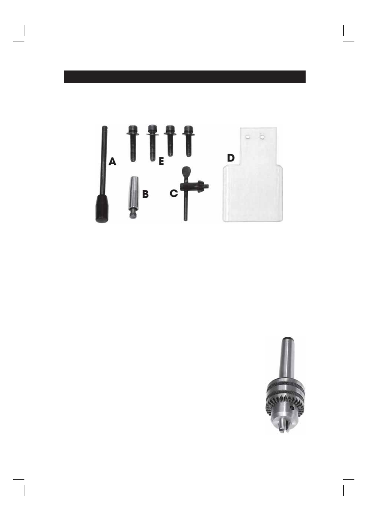
The following loose items are to be found in the packing case.
Fig. 1
A. Spindle Lowering Lever.
B. Handle.
C. Chuck Key.
D. Plastic Guard.
E. Mounting Bolts w/washers
Check the parts off against the above list.
Should there be any deficiencies or damage, you should contact your CLARKE
dealer immediately .
Remove all traces of preservative from the Mill/Drill with a good quality solvent, and
wipe all parts thoroughly with a clean dry cloth. Apply a coating of wax paste or
light oil, to the untreated parts.
In addition to the above, a Drill Chuck is fitted to the spindle.
See Accessories for method of attachment and removal.
Take the necessary precautions when lifting the head
assembly, considering its weight. Assistance may be required.
Before use, the machine must be mounted on to the Variable
Speed Metal Lathe, Model CL250M.
Ensure the location is adequately lit, and that you will not be
working in your own shadow.
7
Page 8
ASSEMBLY
Ensure the power supply to the lathe is disconnected.
If any accessories are attached to the cross slide of the lathe, they must be removed
before fitting the Mill/Drill Head.
Slacken the Tailstock securing bolts and slide it to the end of the bed and secure in
this position.
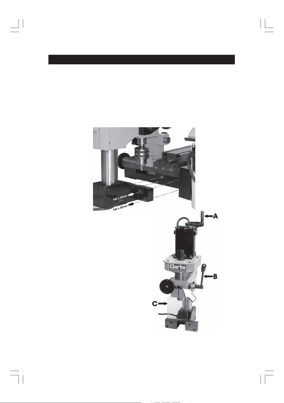
Bolt the Mill/Drill to the Metal Lathe as shown in Fig. 2, using the four hex. socket
head bolts supplied, ensuring the 2x35mm bolts are used for the two top holes, the
2x45mm bolts for the bottom holes, and they are tight.
Fig. 2
Fig. 3
Attach the Head Control Wheel Handle,
‘A’, and the Spindle Lowering Lever, ‘B’,
securing the latter with the single screw,
provided.
Finally bolt on the plastic guard, ‘C’
ensuring the metal block (arrowed) is
between the head and the guard,
tightening the two securing screws using
the hex key provided, (with the lathe).
Finally, plug the Power Cable into the socket on the rear of the Lathe Headstock.
8
Page 9
OPERATION.
Fig. 4
In order to carry out milling or drilling
operations, it will be necessary to provide
some means of securing the workpiece.
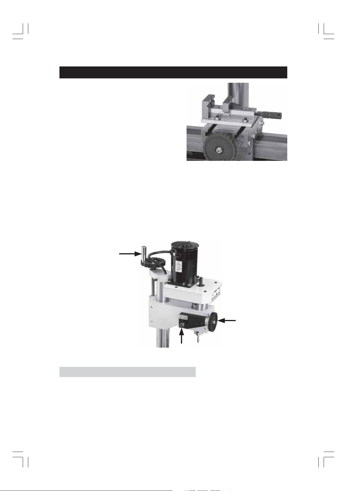
A quick action vise is available as an
accessory from your Clarke dealer. The vise
should be secured to the Cross Slide, using
the four Tee bolts with nuts and washers
provided with the vise, as shown in Fig. 4.
Similarly, a means of holding and securing
a Mill or Drill bit is required.
A Collet set and a Mill Chuck set are available for this purpose, from your Clarke
dealer.
A set of End Mills is also available with sizes ranging from 3 -10mm.
Please refer to the ‘Accessories’ section for an explanation as to how to mount and
use these tools.
With the workpiece secured to the lathes’ Cross Slide (in a vise or otherwise), use
the Cross Slide and Saddle feed handles of the lathe to position it beneath the Mill
or Drill.
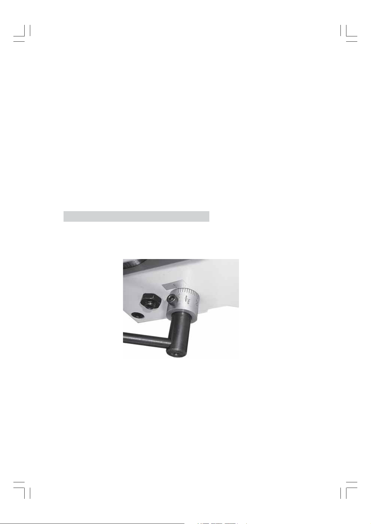
The Mill Head complete is raised or lowered using the handwheel ‘A’, Fig 5.
Fig. 5
A
B
C
The maximum spindle travel using the raising and lowering lever is 30mm.
Milling with Accuracy
Milling, with accuracy, to a specific depth, may be achieved using the handwheel
‘B’ in conjunction with the button ‘C’.
1. Push IN and hold button ‘C’ whilst lowering the Spindle, using the Spindle
Lowering Lever, until the button moves inwards, thereby locking the spindle to
the mechanism controlled by handwheel ‘B’.
9
Page 10
2. Lower the Head complete, using Handwheel ‘A’, until the Mill is a few millimetres
from the workpiece.
3. Turn the handwheel ‘B’ clockwise until the Mill just comes into contact with
the workpiece, then very carefully zero the scale by holding the handwheel
steady and turning the scale independently so that the ‘0’ lines up with the
mark provided on the head.
The machine is now set and prepared for accurate Milling to a specific depth.
Switch ON the Mill (refer to the ‘Starting’ procedure in the Lathe manual).
Turn the handwheel ‘B’ clockwise, observing the scale.....one graduation is
equivalent to 1mm in depth.
It is important to set the spindle speed correctly, according to the job in hand. A
knowledge of Cutting Speeds is therefore necessary.
It is not intended for this booklet to be a tutorial on Milling and Drilling procedures It
is strongly recommended therefore that you consult a suitable reference book on
the subject. Nevertheless, a brief summary is given below as a basis on which to
begin.
Accurate Drilling
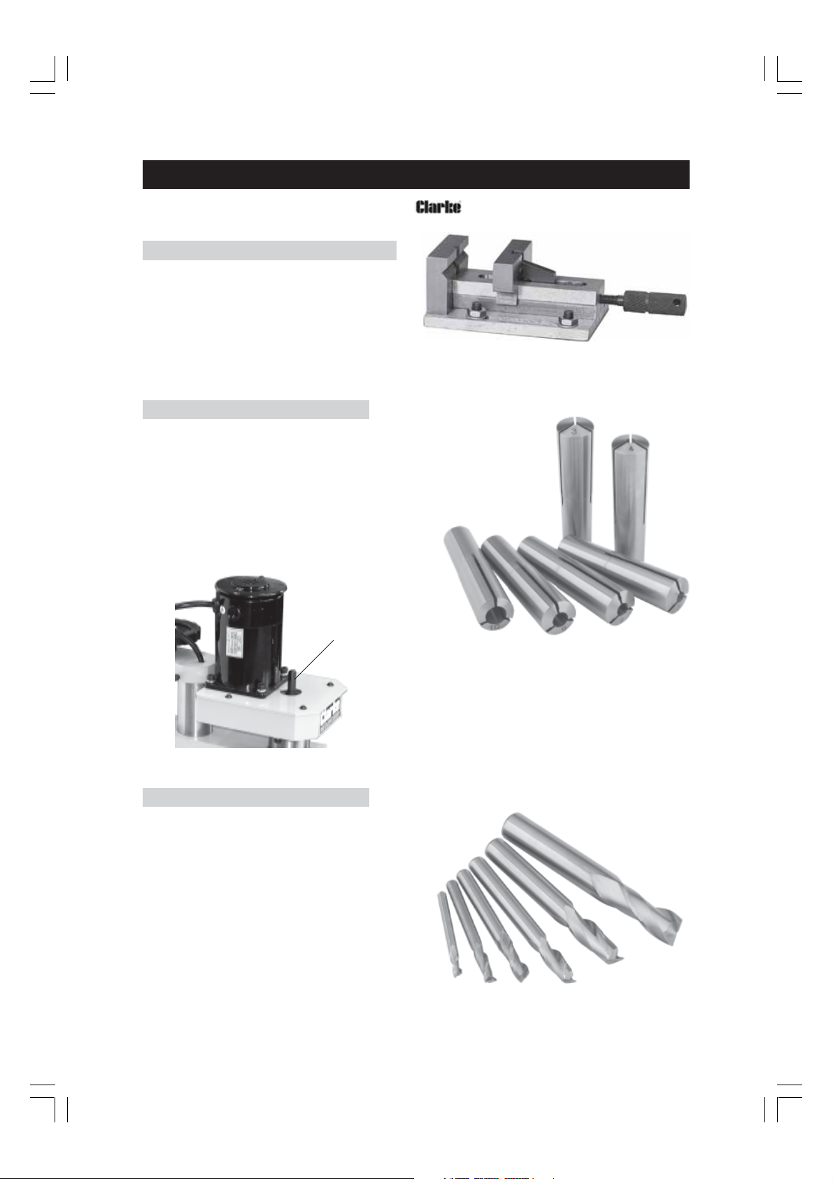
Drilling accurately to a predetermined depth is possible using the Spindle Lowering
lever. A scale shown in Fig.6 is provided, one division of which is equivalent to 1mm
in depth.
Fig. 6
Bring the drill so that it is just in contact with the workpiece using the HEAD Lowering
handle. Slacken the screw securing the scale and turn it the required number of
divisions, corresponding to the depth of desired cut, and secure in this position. i.e
if the drilling depth is 15mm, the 15th division mark should be opposite the zero
mark on the body.
The Spindle lowering lever may now be turned to the required depth for repetitive
drilling if desired.
10
Page 11

MAINTENANCE
For maximum performance, it is essential that the Mill/Drill is properly maintained. Always
inspect before use. Any damage should be repaired, and maladjustments rectified.
If you are unable to rectify any faults, please contact your local dealer or Clarke
International Service Division on 020 8556 4443 for assistance.
Monthly (When in regular use)
Check tightness of mounting bolts, and, head and column securing set screws.
If the mains lead is worn or cut, or damaged in any way, it should be replaced immediately.
Lubrication
All bearings are packed with grease at the factory and require no further lubrication.
Lubricate the Quill Shaft assembly with light oil, weekly.
After use
Remove all swarf from the machine and thoroughly clean all surfaces.
Components should be dry, with machined surfaces lightly oiled.
Always remove Mill/Drill bits, and store in a safe place.
CUTTING SPEEDS
In order to preserve the cutting tool, avoid damaging the workpiece and to produce a good
finish, it is important to ensure the correct Cutting Speeds are used. Cutting Speed is the rate
at which the cutting tool passes over the work, and is given in Feet Per Minute.
Factors which determine the best speed to use in any operation are:
• Kind of material being worked, and its hardness value
• Quality of cut desired
• Type and size of Drill/Mill
• Depth of Cut
• Rate of Feed
As a general guide, the Mill/Drill speed for a given bit size is according to the table below,
using a light to moderate Feed rate. DO NOT force the tool.
Generally, the smaller the Mill/Drill the greater the required RPM. In soft material, the speed
should be higher than for hard metals.
IF you are not familiar with materials and cutting speeds, it is strongly recommended that you consult a
qualified person or attend a suitable course on the subject.
Bit Size
Alum & Brass
Zinc Diecast
Iron & Mild
Steel
3456810
2000 2000 1850 1600 1400 1000
2000 2000 1650 1350 1000 800
11
Page 12
ACCESSORIES
The following accessories are available from your dealer. When ordering, please quote the
part number shown.
1. Quick Vice
With jaws 50mm wide, maximum opening of
37mm and 15mm deep.
‘T’ bolts with nuts and washers are provided for
mounting to the CL250M Lathe cross slide.
Part Number: 7610743
2 . Collet Set (MT2)
Part Number: 7601851
A set of 6 Collets for use with the HSS End Mills:
Insert the appropriate Collet into the spindle.
Insert the the draw bolt, provided, into the
spindle, from the top and screw on to the Collet
a few turns.
Insert the appropriate Mill into the jaws of the
Collet, and tighten the draw bolt.
Fig. 7
Draw
Bolt
3. HSS End Mill (2-Fluted)
Part Number: 7601852
A set of 6 End Mills, of the following sizes,
for use with the Collet Set (see above)
• 3mm
• 4mm
• 5mm
• 6mm
• 8mm
• 10mm
To remove the Collet, unscrew the draw bolt a few turns
and tap its head with a mallet to break the seal
between the Collet and spindle.
NOTE: A hole in the Spindle allows a tommy bar (not
provided) to be inserted so that the spindle may be held
whilst tightening/loosening is carried out.
12
Page 13
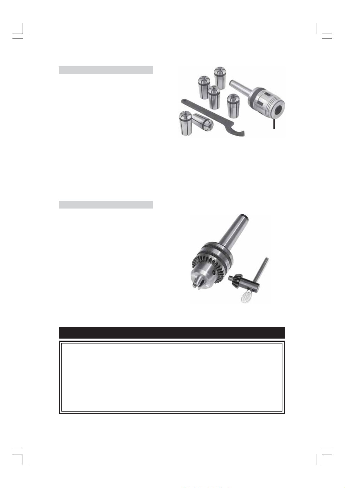
4. Mill Chuck Set
Part Number: 7601853
A set of 6 collets with chuck with sizes:
•3mm
•4mm
•5mm
•6mm
•8mm
• 10mm
1. Insert the shank of the chuck into the Mill Head Spindle and screw on to the end of the draw bolt,
shown in Fig 7, page 12. Tighten the draw bolt, holding the spindle steady by hand or by using a
tommy bar (not provided) in the hole provided in the spindle.
2. Unscrew and remove the end collar ‘A’, insert the appropriate collet and reattach the end collar.
3. Insert the respective end mill into the collet and tighten using the ‘C’ spanner.
To remove the chuck, undo the draw bolt a turn or two, then tap its’ head using a mallet to break the seal.
A
5. Drill Chuck with Key
Part Number: CL251MH910
Insert the shank of the chuck into the spindle and
screw on to the end of the draw bolt, shown in
Fig 7, page 12.
Tighten the draw bolt, holding the spindle steady
by hand or by using a tommy bar (not provided),
in the hole provided in the spindle.
To remove the chuck, undo the draw bolt a turn
or two, then tap its’ head using a mallet to break
the seal.
SPARE PARTS & SERVICING
For Spare Parts or Servicing, please contact your nearest dealer, or
CLARKE International, on one of the following numbers.
PARTS - 020 8558 6696 : SERVICE - 020 8556 4443
PARTS & SERVICE FAX - 020 8 558 3622
PARTS E-MAIL - [email protected]
SERVICE E-MAIL - [email protected]
NOTE: This tool is supplied with the machine.
13
Page 14

PARTS LIST
No: Description Qty Part No:
133 Handle bolt 1 SG251MH133
134 Handle sleeve 1 SG251MH134
135 Handwheel 1 SG251MH135
136 Leadscrew bkt 1 SG251MH136
137 Lifter 1 SG251MH137
138 Key 3x10 1 SG251MH138
139 Fuselage 1 SG251MH139
140 Screw M6x35mm 2 SG251MH140
141 Screw M6x45mm 2 SG251MH141
142 Fuselage bracket 1 SG251MH142
144 Motor cover 1 SG251MH144
145 Screw M6x12 5 SG251MH145
146 Spacing ring 1 SG251MH146
147 Motor gear 1 SG251MH147
149 Up cover plate 1 SG251MH149
150 Quill fixed plate 1 SG251MH150
151 Gear box 1 SG251MH151
152 Spindle quill 1 SG251MH152
154 Ball bearing 2 SG251MH154
155 Spindle base 1 SG251MH155
156 Safety cover 1 SG251MH156
157 Check Ring 20 1 SG251MH157
158 Spindle gear 1 SG251MH158
159 Spacing ring 1 SG251MH159
160 Nut M241.5 1 SG251MH160
161 Washer 24 1 SG251MH161
162 Check ring 38 2 SG251MH162
163 Compr. spring 1 SG251MH163
164 Spring support 1 SG251MH164
165 Long handle 1 SG251MH165
166 Lever cap M8x40 1 SG251MH166
167 Read out sleeve 1 SG251MH167
168 Spring pin 3x12 2 SG251MH168
170 Gear shaft 1 SG251MH170
171 Spacing ring 1 SG251MH171
172 Connecting screw 1 SG251MH172
173 Bevel gear 1 SG251MH173
174 Worm base 1 SG251MH174
175 Screw M5x18 1 SG251MH175
No: Description Qty Part No:
176 Pin 3x12 1 SG251MH176
177 Connect shaft 1 SG251MH177
178 Pin 3x18 1 SG251MH178
179 Worm shaft 1 SG251MH179
180 Dial 1 SG251MH180
181 Lock bolt 1 SG251MH181
182 Key 4x12 1 SG251MH182
183 Drill spindle 1 SG251MH183
184 Taper shank B12 1 SG251MH184
189 Main Label 1 SG251MH189
191 Small Label 1 SG251MH191
192 Fine feeding label 1 SG251MH192
193 Screw M6x20 1 SG251MH193
196 Cap nut M6 2 SG251MH196
197 Washer 6 5 SG251MH197
198 Screw M5x8 3 SG251MH198
199 Handwheel 1 SG251MH199
200 Spring steel 1 SG251MH200
201 Key 2X10 1 SG251MH201
202 Washer 4 4 SG251MH202
203 Cap screw M4x8 4 SG251MH203
204 Check ring 8 2 SG251MH204
205 Key 3x6 1 SG251MH205
206 Spring washer 6 5 SG251MH206
207 Motor 1 SG251MH207
208 Cap screw M4x12 2 SG251MH208
209 Screw M8x40 5 SG251MH209
210 Washer 8 5 SG251MH210
211 Site screw 1 SG251MH211
212 Flat washer 10 1 SG251MH212
213 Nut M10 1 SG251MH213
214 Block 1 SG251MH214
215 Chuck guard 1 SG251MH215
216 Flat washer 4 2 SG251MH216
217 Screw M4x14 2 SG251MH217
218 Power Cable compl. 1 SG251MH218
Accessories:
• Drill chuck with key 1 SG251MH910
14
Page 15
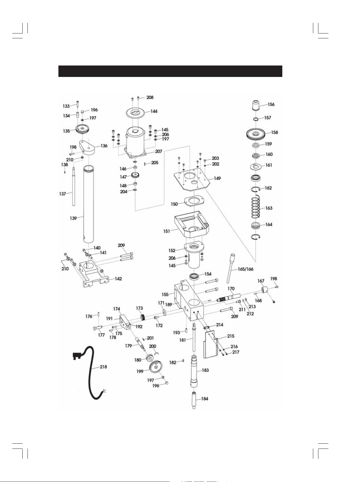
PARTS DIAGRAM
15
 Loading...