

Clarke Strong Arm HTL 300, Strong Arm HTL 500, 7610152, 7610148 Operating & Maintenance Instructions
Page 1
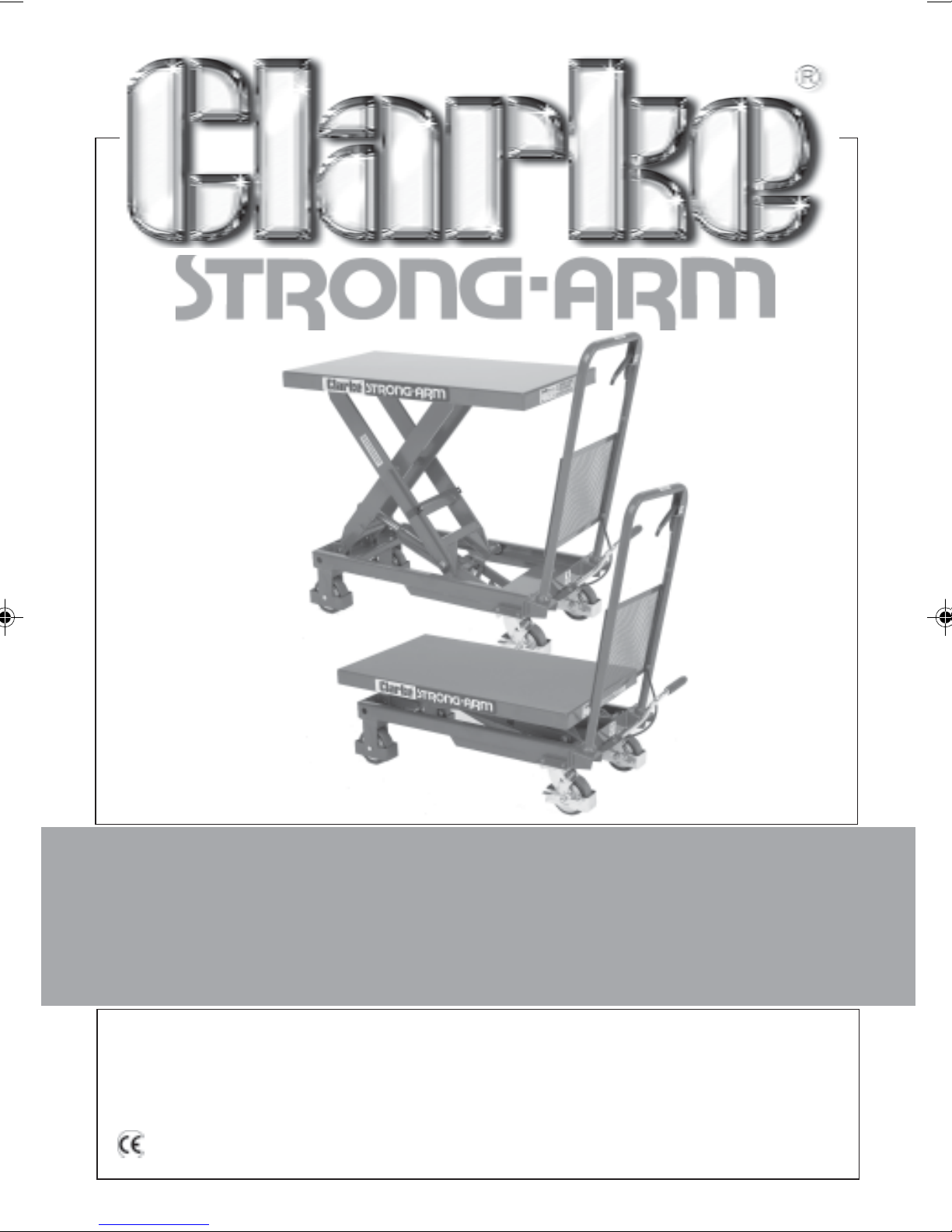
HYDRAULIC MOBILE
HYDRAULIC MOBILE
LIFTING TABLE
LIFTING TABLE
MODEL Nos. HTL300 & HTL500
OPERATING & MAINTENANCE
INSTRUCTIONS
0611
Page 2
SPECIFICATIONS
HTL 300 HTL 500
Part No. 7610148 7610152
Maximum Safe Working Load 300kg 500kg
Maximum Lifting Height 900mm 900mm
Minimum Lifting Height 340mm 340mm
Gross Weight 81kg 90kg
Dimensions 930x500x350mm 930x500x350mm
Hydraulic Oil (-10 to 40OC YBN32 YBN32
conforming to ISO VG32) or equivalent or equivalent
Please note that the details and specifications contained herein, are correct at the time of going to print. However,
NOTE: When de-commissioning this equipment, ensure the oil is drained completely
and disposed of according to local ordinances/regulations.
CLARKE International reserve the right to change specifications at any time without prior notice.
SPARE PARTS & SERVICING
IMPORTANT!
We strongly recommend that ALL replacement parts be purchased from Clarke
International through one of its approved dealers. We accept no responsibility
whatsoever for failure of the equipment due to parts purchased from a third party.
For Spare Parts and Service, please contact your nearest dealer, or CLARKE International,
on one of the following numbers.
PARTS & SERVICE TEL: 020 8988 7400
or e-mail as follows:
PARTS: [email protected]
SERVICE: [email protected]
2
Page 3

Thank you for purchasing this CLARKE Mobile Hydraulic Lifting Table, designed for
the quick and convenient raising of components or equipment in and around a
workshop.
All authorised users must read this leaflet thoroughly and carefully follow the
instructions given. This will ensure the safety of the operator and that of others in the
vicinity, and you can also look forward to the Lifting Table giving long and
satisfactory service.
SAFETY PRECAUTIONS
• Only use the Lift for the purpose for which it was intended. NEVER exceed
its capacity - HTL300 - 300kg.......HTL500 - 500kg
• DO NOT use for lifting, lowering or transporting personnel.
• ALWAYS ensure the load is centralised on the table and is completely stable before
lifting or moving. DO NOT secure by hand alone, use straps where necessary.
• NEVER transport a load in the raised position.
• ALWAYS apply the brakes before lifting or lowering, when the lift is left unattended, or
when stationary on an incline.
• ALWAYS ensure the table is left in its FULLY LOWERED position when the Lift is
not in use.
• DO NOT use the Lift on rough terrain. It is designed for use on smooth surfaces only.
• ALWAYS open the release valve slowly in order that load descends in a
controlled manner.
• ALWAYS wear proper apparel, including coveralls, and safety shoes when
using workshop equipment.
• Take all necessary precautions when handling heavy equipment. Be aware
that moving equipment of 0.3 tonnes or 0.5 tonnes can be extremely
hazardous. The equipment MUST be adequately secured when the table is
moved.
• Be aware that the cantilever action poses a severe hazard. Do not allow any
body parts/materials/equipments to come into contact with or interfere with
its operation. Keep feet well away when lowering.
• Be aware that excessive force may be required to move a load of 0.3 - 0.5 tonnes.
Take all precautions when moving and stopping to ensure it is carried out under
complete control. Be aware of what is happening in the immediate vicinity, and
anticipate possible hazards...blind corners, overhead obstructions etc.
• Take great care when lowering a load, that the hands are not trapped by the
load.
3
Page 4
ASSEMBLY
Lower the Handle into the holes in the frame and secure, each side, from below,
with the bolt (64), spring and flat washers (63 & 62), provided.
Insert Foot Lever (59) into its Socket at the end of lever (60). Insert Pin (42) and
secure with washers (6 & 11) and nut (12).
OPERATION
Before commencing to raise or lower the Lift:
1. Ensure the load is completely stable and evenly displaced on the table
and secured if necessary.
2. Ensure that no obstacles can snag or prevent the Lift from being raised.
3. Lock the castor brakes. (A safety device, (brake) is provided on each castor)
RAISE:
1. Pump the Foot Lever (59) so that the table reaches the desired height.
(The Release Lever (65) is spring loaded to return it to its closed position).
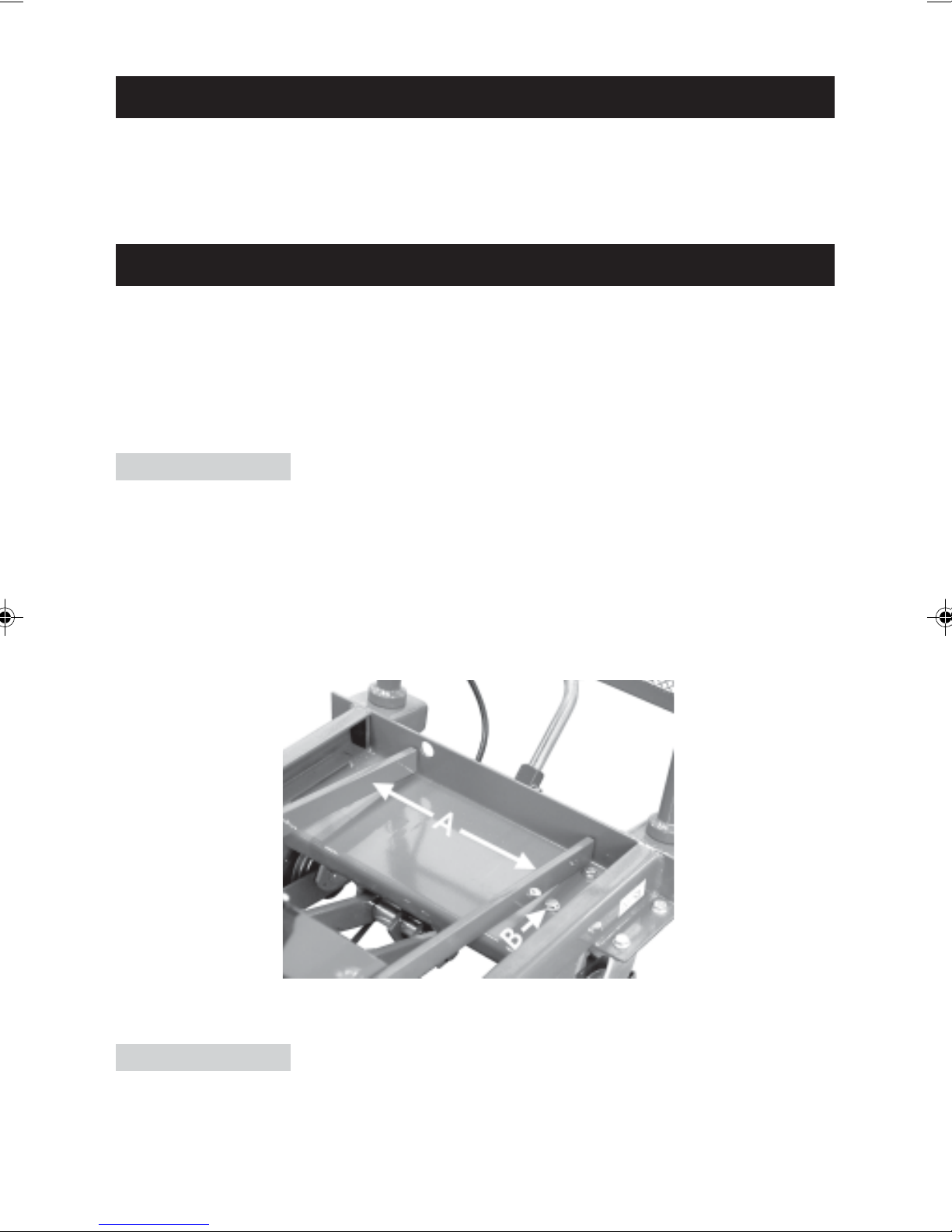
SAFETY BARS (‘A’ Fig.1)
IMPORTANT! When working with the table raised, the safety bars must be put in
place and the table lowered so that the load is supported by the safety bars and
not the hydraulic ram, as shown in the illustration below. The safety bars are
secured with a clip, one to each leg of the lift.
Fig.1
Take care to ensure, when lowering, that the safety bars do not foul the bolt heads
arrowed at ‘B’.
LOWER:
Slowly pull the Release Lever (65) upwards. Ensure the load is lowered in a fully
controlled manner - do not jerk the lever upwards.
Releasing the Lever will cause the table to stop at any desirable height.
4
Page 5

MAINTENANCE
DAILY
Inspect the lift for signs of obvious damage, distortion of components, damage to
castors etc.
Check the ram for signs of hydraulic oil leakage.
If any of the above are apparent - DO NOT use the lift. Have it inspected by a
qualified person and repaired if necessary.
Be aware that oil leaks can produce extremely hazardous environmental
conditions. ALL leaks must be cleaned immediately and sand/sawdust or similar
should cover the contaminated area (which should be isolated), until it is
completely cleaned and dried.
MONTHLY
• Check that all joints and pivots are clean and moving freely. Lubricate all pivots with
light oil and lightly grease the channels in which the wheels are located.
• Check the action of the hydraulic ram and inspect for leaks. If leaks are
apparent, DO NOT USE THE LIFT, but submit for repair. (Contact your Clarke
dealer).
regulations and should therefore be carried out by your CLARKE dealer.
NOTE: ALL major repairs MUST be re-tested according to ANNEX C
• Check castor brake action and ensure that the Lift is held securely when
they are applied.
TROUBLESHOOTING
PROBLEM CAUSE SOLUTION
Trucks will not operate or
lifting height is insufficient
Platform rises, then
lowers
Platform will not lower Pin (28) - inadequate
1. Non-return valve steel
ball (23) is not seated
2. Pin (28) bears heavily
on steel ball
3. Insufficient hydraulic oil
1. Non-return valves (23, 24,
16), not seated correctly
2. As (2) above
movement
1. Clean valve hole and
replace ball
2. Adjust cable (2) at the adjuster
(3&4) so that free play exists
between ball and pin
3. Top up oil to correct level
1. Clean valve holes and
replace balls
2. As (2) above
Adjust cable at the adjuster
3&4 so that movement is
sufficient to open ball valve
Oil Leak at pin (28) O-Rings (29) damaged Replace O-Ring
Oil Leak at Pump element
(5) and piston rod (44)
Seal rings (1, 3, 47, & 48) are
damaged
5
Replace seals
Page 6
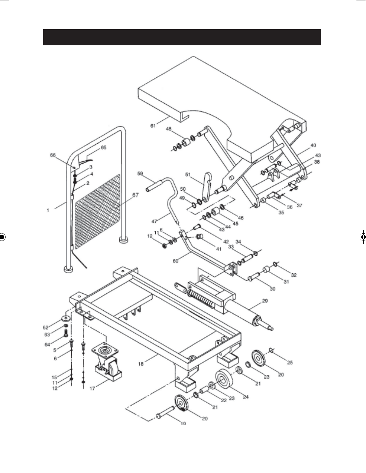
PARTS DIAGRAM
6
Page 7
PARTS LIST
No.Description Qty Part No.
I Handle bar 1 ZJ30001
2 Pull Rod 1 ZJ30002
3 Nut 1 ZJ30003
4 Screw 1 ZJ30004
5 Bolt 8 ZJ30005
6 Washer 9 ZJ30006
11 Washer 9 ZJ30011
12 Nut 9 ZJ30012
15 Washer 8 ZJ30015
17 Universal wheel 2 ZJ30017
18 Frame 1 ZJ30018
19 Shaft 2 ZJ30019
20 Cover 4 ZJ30020
21 Washer 4 ZJ30021
22 Screw 4 ZJ30022
No. Description Qty Part No.
36 L-pin 4 ZJ30036
37 Screw 4 ZJ30037
38 Pin 1 ZJ30038
40 Arm (300) 1 ZJ30039
40 Arm (500) 1 ZJ50039
41 Cushion 1 ZJ30041
42 Bolt 1 ZJ30042
43 Retaining ring 6 ZJ30043
44 Washer 4 ZJ30044
45 Roller 2 ZJ30045
46 Washer 2 ZJ30046
47 Pedal bar 1 ZJ30047
48 Roller 2 ZJ30048
49 Retaining ring 2 ZJ30049
50 Washer 2 ZJ30050
23 Bearing 4 ZJ30023
24 Wheel 2 ZJ30024
25 Retaining ring 2 ZJ30025
29 Pump unit 1 ZJ30029
30 Short shaft 1 ZJ30030
31 Bush 1 ZJ30031
32 Retaining ring 2 ZJ30032
33 Short shaft 1 ZJ30033
34 Retaining ring 2 ZJ30034
35 Bush 2 ZJ30035
51 Support 2 ZJ30051
59 Protecting cover 1 ZJ30059
60 Connecting 1 ZJ30060
61 Table 1 ZJ30061
62 Washer 2 ZJ30062
63 Washer 2 ZJ30063
64 Nut 2 ZJ30064
65 Handle 1 ZJ30065
66 Pin 1 ZJ30066
67 Mesh Guard 1 ZJ30067
PARTS and SERVICE CONTACTS
For Spare Parts and Service, please contact your nearest dealer, or CLARKE International,
on one of the following numbers.
PARTS & SERVICE TEL: 020 8988 7400
or e-mail as follows:
PARTS: [email protected]
SERVICE: [email protected]
7
Page 8
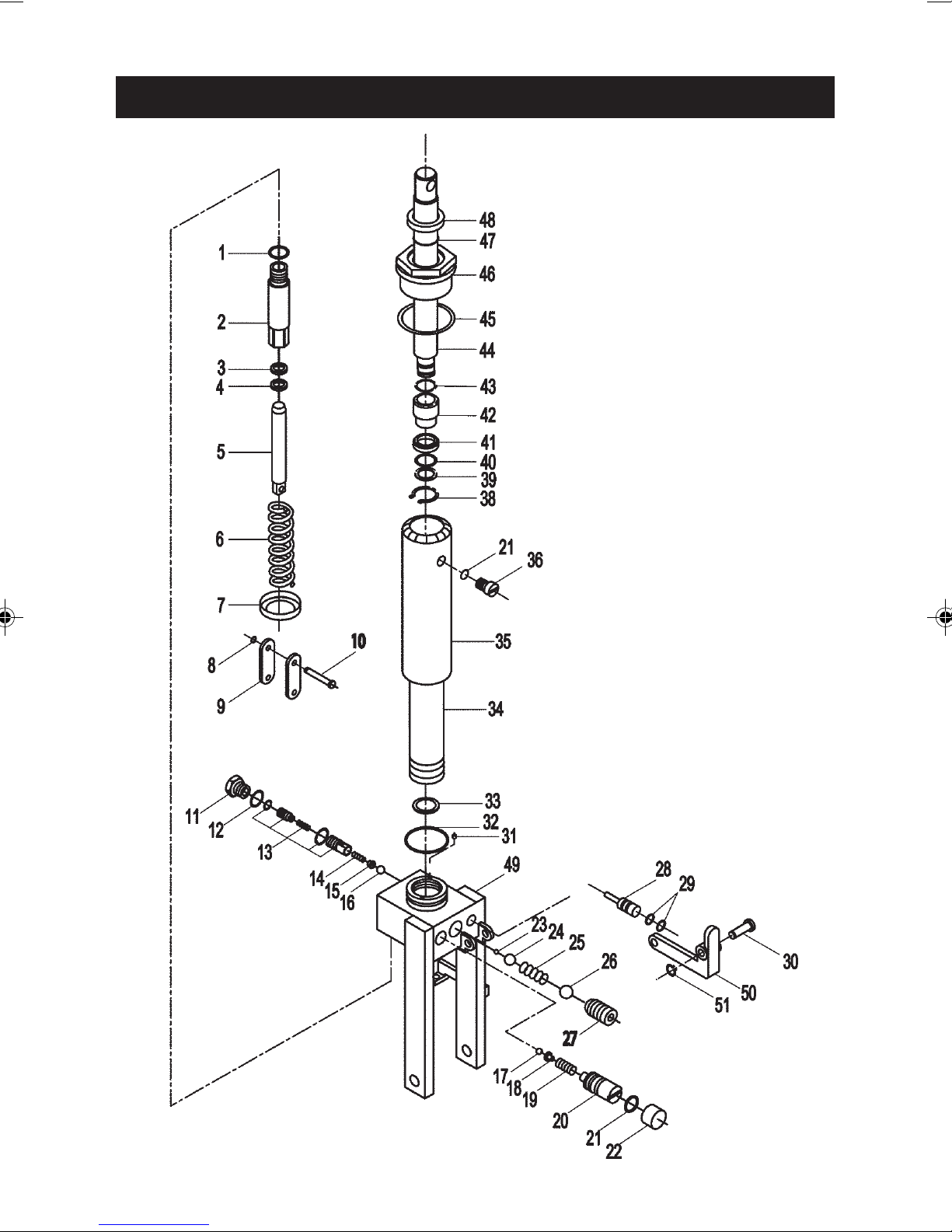
PARTS DIAGRAM - RAM
8
Page 9
PARTS LIST - RAM
No. Description Qty Part No.
I O-ring 22x2.65 I ZJ300R01
2 Pump cylinder (300) I ZJ300R02
2 Pump cylinder (500) I ZJ500R02
3 Seal ring (300) I ZJ300R03
3 Seal ring (500) I ZJ500R03
4 Dust ring (300) I ZJ300R04
4 Dust ring (500) I ZJ500R04
5 Pump plunger (300) I ZJ300R05
5 Pump plunger (500) I ZJ500R05
6 Spring I ZJ300R06
7 Spring seat 1 ZJ300R07
8 Retaining ring I ZJ300R08
9 Joint plate 2 ZJ300R09
10 Pin I ZJ300R10
No. Description Qty Part No.
24 Steel Ball I ZJ300R24
25 Spring I ZJ300R25
26 Steel ball I ZJ300R26
27 Screw I ZJ300R27
28 Strike pin I ZJ300R28
29 O-ring 6.9x1.8 2 ZJ300R29
30 Shaft I ZJ300R30
31 Filter I ZJ300R31
32 O-ring 65x3.55 I ZJ300R32
33 Sealing Ring 1 ZJ300R33
34 Cylinder I ZJ300R34
35 Housing I ZJ300R35
36 Screw I ZJ300R36
38 Retaining ring I ZJ300R38
11 Plug I ZJ300R11
12 Copper washer I ZJ300R12
13 Damp valve I ZJ300R13
14 Spring I ZJ300R14
15 Spring seat I ZJ300R15
16 Steel ball I ZJ300R16
17 Steel ball I ZJ300R17
18 Spring seat I ZJ300R18
19 Spring I ZJ300R19
20 Adjusting screw I ZJ300R20
21 O-ring 7.5x2.65 2 ZJ300R21
22 Cover ring I ZJ300R22
23 Steel ball I ZJ300R23
39 Washer I ZJ300R39
40 O-ring 33.5x3.55 I ZJ300R40
41 Cup packing I ZJ300R41
42 Bush I ZJ300R42
43 O-ring 20x2.65 I ZJ300R43
44 Piston rod I ZJ300R44
45 Sealing Ring 1 ZJ300R45
46 Cylinder cap I ZJ300R46
47 O-ring 31.5x3.55 I ZJ300R47
48 Rubber seal I ZJ300R48
49 Base I ZJ300R49
50 Lever plate I ZJ300R50
51 Retaining ring I ZJ300R51
9
Page 10
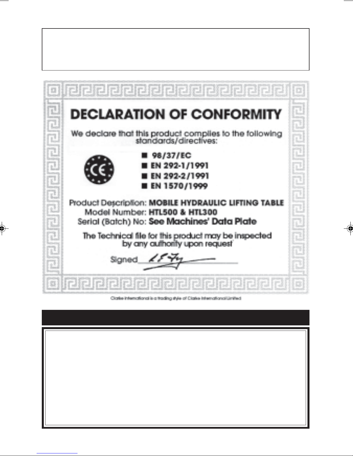
IMPORTANT!
The notice at the control position stating that, ‘only authorised persons
are allowed to use this machine’, must always be in place and
renewed if it becomes defaced.
This CLARKE product is guaranteed against faulty manufacture for a period
of 12 months from the date of purchase. Please keep your receipt as proof
of purchase.
This guarantee is invalid if the product is found to have been abused or
tampered with in any way, or not used for the purpose for which it was
intended.
Faulty goods should be returned to their place of purchase, no product can
be returned to us without prior permission.
This guarantee does not effect your statutory rights.
GUARANTEE
10
Page 11

11
Page 12
 Loading...