

Page 1
JETSTAR 1700
JETSTAR 1700
POWERWASHER
POWERWASHER
Part No. 7333055
OPERATING & MAINTENANCE
INSTRUCTIONS
0401
©
Page 2
DECLARATION OF CONFORMITY
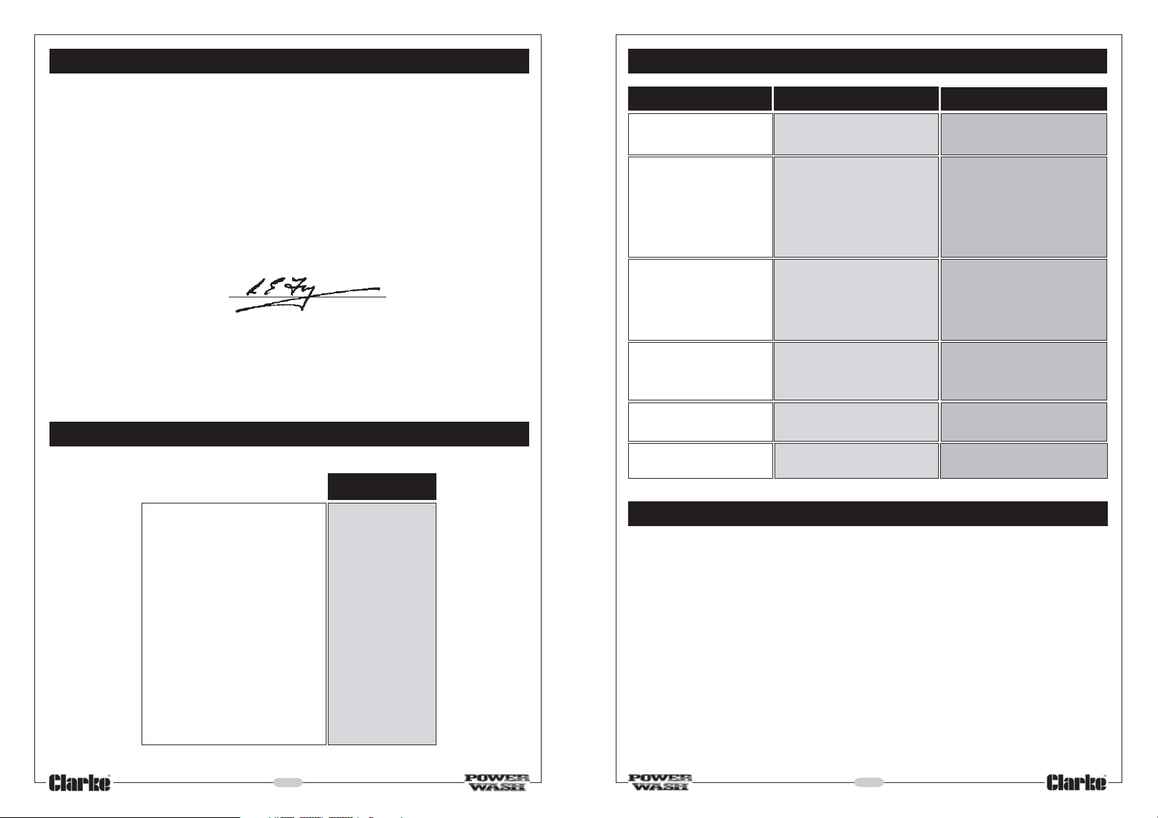
TROUBLESHOOTING
We declare that this product complies with the following standards/directives:
• 73/23 EEC
• 98/37 EEC
• 89/336 EEC
• 93/68 EEC
• EN60 335-1
• EN292 2
See data plate for serial/batch number
signed
SPECIFICATIONS
Jetstar 1700
Fault Cause Remedy
Pressure Drops or Oscillates
Motor hums when switched
ON but fails to start
Machine fails to start, no
sound from motor
Motor stops
No detergent delivered
Irregular jet produced
Lack of Water
Water Filter blocked
Mains voltage low
Gun not activated
Power lead extension cable too
small
Plug not connected correctly
Incorrect power voltage
Mains fuse blown or RCD tripped
Thermal Overload has
intervened
Injector clogged
Container empty
Dirty high pressure nozzle in spray
gun
Check the water tap is fully ON
Clean water filter
Check electrical connections
On switching ON the machine,
operate the gun
Use an extension with
conductors of sufficient cross
section. (See Electrical
Connections)
Check plug and lead and
repair/replace accordingly.
Check the plug, cable and
switch.
Renew fuse or reset RCD
Check to ensure the power
voltage is correct, wait for 5
minutes before trying to start
again. (See Thermal Overload)
Clean the spray gun nozzle
Fill container
Clean high pressure nozzle
Motor 230V 50Hz 1Ph
Power Rating 1,3kW
Max. Pressure 100Bar (1500psi)
Max. Water Flow 6 Litre/min
Max. Inlet Water Temp. 40°C
Detergent Tank Capacity 0.5L
Gross Weight 11kg
Dimensions 370x190x290mm
Noise Level (at 1M) 73dB(A)
Part Number 7333055
2
ACCESSORIES
The range of accessories listed below may be purchased from your CLARKE dealer.
Item Part No.
DIY Car Brush ........................................................................ 7310020
Water Sandblaster............................................................... 7310106
Drain Cleaner ...................................................................... 7310117
Turbo Nozzle ......................................................................... 7334000
Extension Hose 10M ............................................................. 7310120
5 Litres Detergent (Traffic Film Remover) .......................... 3050821
25 Litres Detergent (Traffic Film Remover) ........................ 3050820
5 Litres Wash ‘n’ Wax ........................................................... 3050815
Sand (For use with Sand blaster) ....................................... 7320005
15
Page 3
LANCE & ACCESSORIES
Thank you for purchasing this CLARKE Jetstar 1700 Powerwasher.
This machine is a lightweight, portable, high pressure power washer,
designed for DIY use only.
It comprises an electric motor, a pump, a high pressure hose with a trigger
and lance, and a foam lance for injecting cleaning agents into the water
jet, ideal for cleaning greasy engines and equipment, removing oil spots
from patios etc.
Before attempting to use your Jetstar 1700, please read this instruction
manual thoroughly and follow all instructions carefully. By doing so you will
ensure the safety of yourself and that of others around you, and you can
look forward to it giving you long and satisfactory service.
GUARANTEE
This CLARKE product is guaranteed against faulty manufacture for a
period of 12 months from the date of purchase. Please keep your receipt
as proof of purchase. This guarantee is invalid if the product is found to
have been abused or tampered with in any way, or not used for the
purpose for which it was intended.
Faulty goods should be returned to their place of purchase, no product
can be returned to us without prior permission. This guarantee does not
effect your statutory rights.
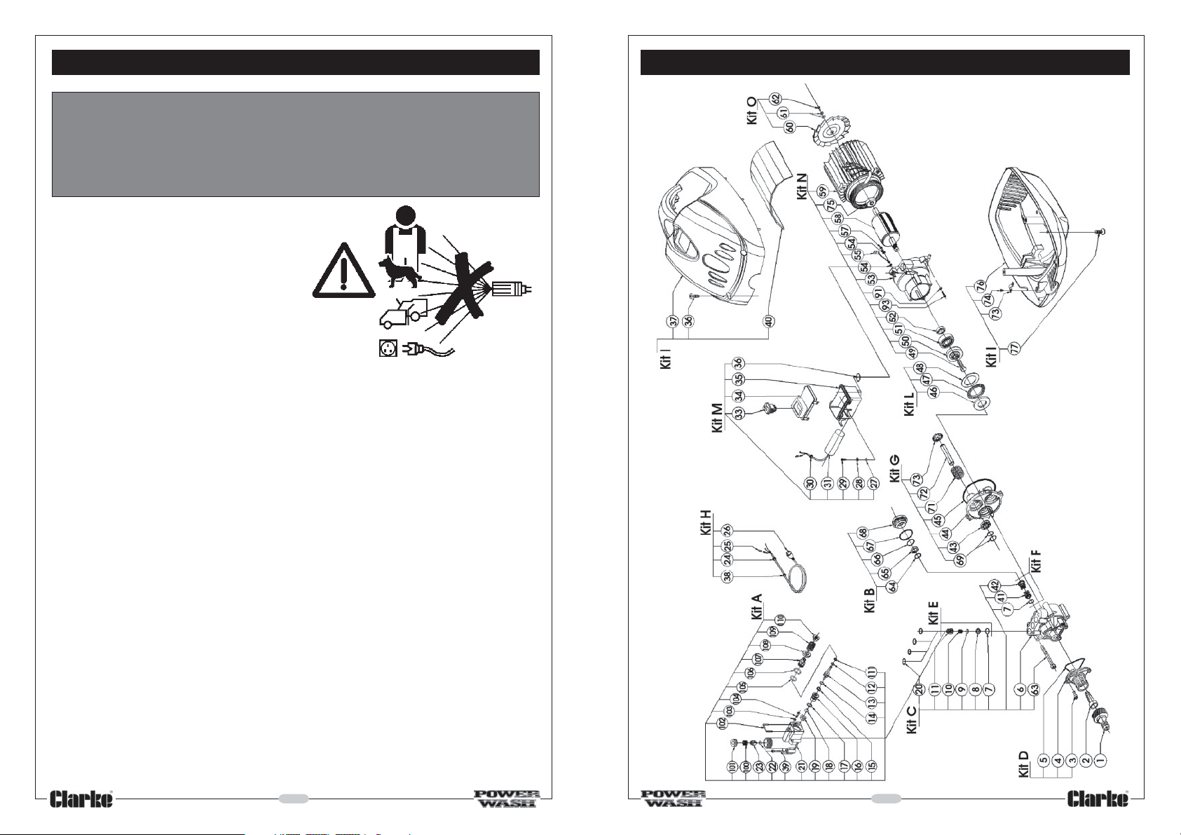
SPARE PARTS LIST
No. Description Part No.
1
1 Hose Fitting Kit KTR182976
2 Suction Filter Kit KTR182975
3 Screw Kit KTR182973
5 0-ring Kit KTR182974
45 0-ring Kit 594 KTR182977
73 Clamp Kit 599 KTR182982
91 Washer Kit 604 KTR182987
KA Manifold Kit KTR184110
KB Packing Retain.kit KTR182762
KC Head Kit KTR184111
KD Intake Connect.kit KTR184112
KE Small Valve Kit KTR182765
KF Small Valve Kit KTR182766
No. Description Part No.
KG Crankcase Kit KTR182767
KH Cable Kit KTR184113
KI Red Cover Kit KTR184114
KL Roller Bear Kit KTR182770
KM Control Board Kit KTR184115
KN Motor Kit KTR184116
KO Impeller Kit KTR184117
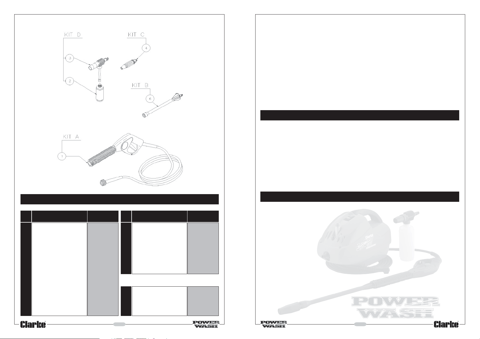
LANCE & ACCESSORIES
KA Gun Kit KTRI84124
KB Extension Kit KTR183571
KG Head Kit KTRI84125
KD Foam Device KTRI83573
14
CONTENTS
Specifications ...................................................................................... 2
Safety Precautions .............................................................................. 4
Parts and Service Contacts ............................................................... 5
Electrical Connections ....................................................................... 6
Pre-Assembly Checks ......................................................................... 7
Assembly and Preparation for Use ................................................... 8
Operation ............................................................................................ 9
Thermal Overload ............................................................................... 11
Cleaning Agents ................................................................................. 11
Care & Maintenance ......................................................................... 12
Spare Parts Diagram ........................................................................... 13
Spare Parts List ..................................................................................... 14
Troubleshooting ................................................................................... 15
Accessories .......................................................................................... 15
3
Page 4
SAFETY PRECAUTIONS
WARNING!
Water at high pressure can be dangerous and may cause severe damage
to persons or property if subject to misuse.
NEVER allow anyone to operate this equipment unless they are thoroughly
reliable, and completely familiar with the safety precautions.
1. Never direct the spray jet at
any person or animal.
2. Never hold a finger over the
high pressure nozzle.
3. Never direct the spray jet at the
machine itself or any other
electrical equipment.
4. After use, and before disconnecting hoses, release the pressure in the
high pressure hose by operating the trigger. Do not attempt to
disconnect any hose or coupling with pressure still in the hose.
5. Never operate the machine with any of the covers removed.
6. Do not, attempt any electrical or mechanical repair. If you have a
problem with your machine contact your local dealer or Clarke
Customer Services Dept., tel: 020 8988 7400
SPARE PARTS DIAGRAM
7. Never supply any liquid other than CLEAN water to the water inlet.
8. Use only chemical cleaning agents (detergents) approved for power
washing when using the foam lance.
9. Never use the foam lance to introduce solvents eg. paint thinners,
petrol, oil, etc.
10. Do not operate the machine whilst standing on ladders: use a platform
tower or scaffolding.
11. Children should not be allowed to use the machine.
12. We recommend the use of safety goggles when using machine with
sand blasting attachment (optional accessory - see Page 14), or any
application where loose particles of stone or grit etc. may be blown
around by the high pressure spray.
4
13
Page 5
ACCESSORIES
Your power washer can be used with a wide range of optional accessories
available from your local dealer (see page 15 for a full list ).
CARE AND MAINTENANCE
WARNING:
Ensure the plug is removed from the socket before carrying out
any adjustment, servicing or maintenance.
After each use
If cleaning agents have been used, thoroughly clean the detergent lance
and bottle with clean water.
Fig.9
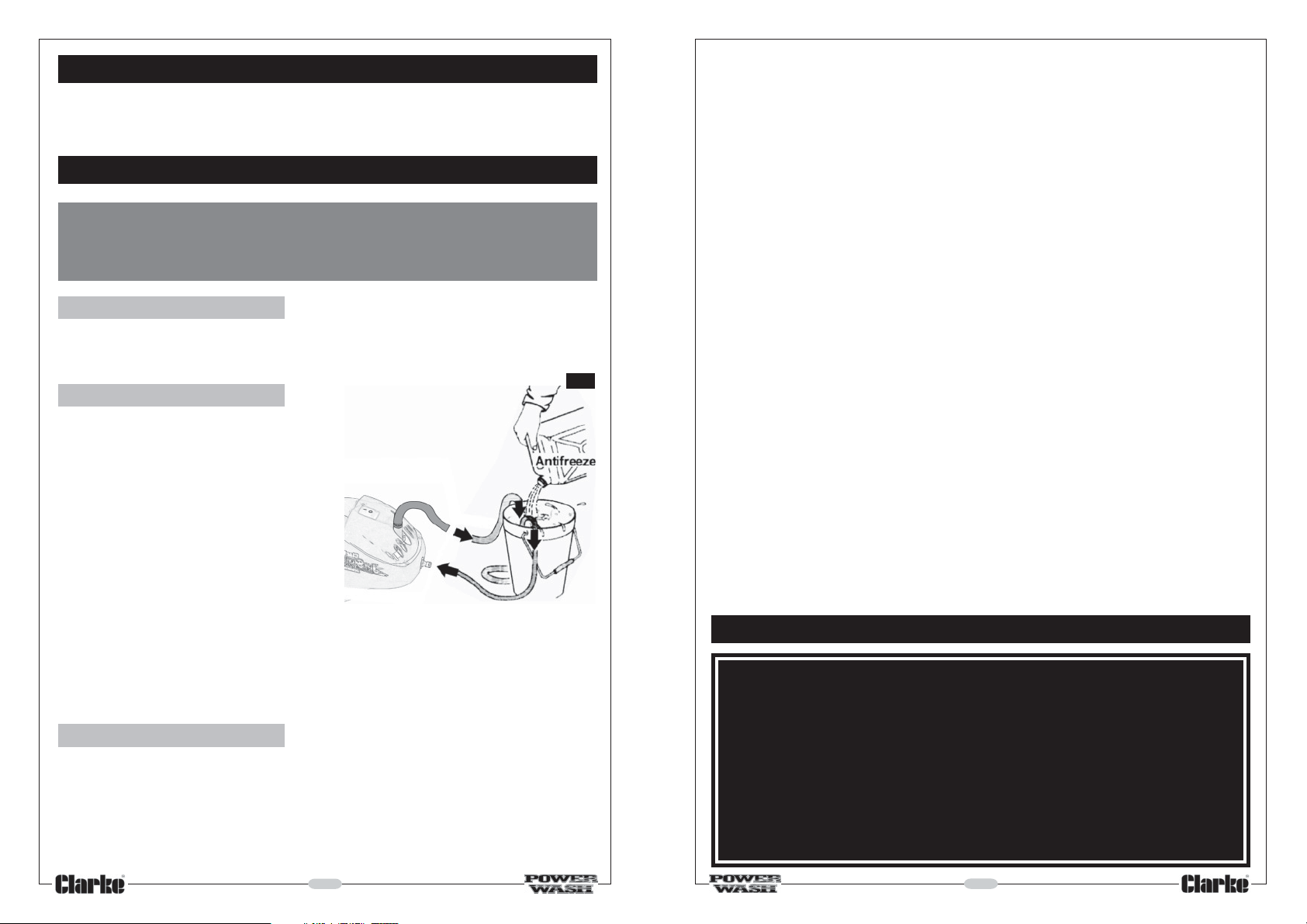
Storage
If there is a danger of freezing, insert
the inlet and outlet hoses into a
bucket of antifreeze as shown in
Fig.9. Start the machine and allow
the antifreeze to circulate. After a
short time, stop the machine and
store with the antifreeze still within
the pump body.
13. When not in use, disconnect from the water and electrical supply’s,
and ensure the system is completely drained. Store in a dry, frost free
environment.
14. Disconnect from the mains supply before carrying out any
maintenance or servicing.
15. Never carry the washer by the power cable, or yank it to disconnect
from the socket.
16. Keep the cable away from heat, oil or sharp edges.
17. Keep all connections dry. Do not touch the plug with wet hands.
18. Do not allow the high pressure hose to become crushed, stretched,
kinked or twisted.
19. Do not pull the washer by the high pressure hose.
20. ALWAYS operate the machine in an upright position and as far away
from the spray site as possible.
21. ALWAYS connect the machine to the power supply through a Residual
Current Device (RCD), readily available from electrical stores, DIY
stores etc.
NOTE:
If you experience difficulty in starting the motor following a long period of
storage, it is possible that the seals within the pump have dried out and
are gripping the pistons. This problem may be alleviated by storing the
machine with antifreeze within the pump body, as described above.
If the seals are stuck however, contact your Clarke dealer for advice.
Water input filter
Located behind the water inlet, this filter should be removed for cleaning
after every 10 hours of use (or less if water is contaminated).
Remove the filter by unscrewing the input hose connection and
withdrawing the filter element.
Clean the element with fresh water. To replace, reverse the above
procedure ensuring that all seals are in place.
PARTS & SERVICE CONTACTS
For Spare Parts and Service, please contact your nearest dealer,
or CLARKE International, on one of the following numbers.
PARTS & SERVICE TEL: 020 8988 7400
PARTS & SERVICE FAX: 020 8558 3622
or e-mail as follows:
PARTS: [email protected]
SERVICE: [email protected]
512
Page 6
ELECTRICAL CONNECTIONS
THERMAL OVERLOAD
WARNING: THIS MACHINE MUST BE EARTHED.
This product is provided with a standard 13 amp, 230 volt (50Hz). BS 1363 plug, for
connection to a standard, domestic electrical supply. Should the plug need
changing at any time, ensure that a plug of identical specification is used.
IMPORTANT: The wires in the mains lead should be wired up in accordance with
the following colour code:
Green & Yellow - Earth
Blue - Neutral
Brown - Live
As the colours of the wires in the mains lead may not correspond with the coloured
markings identifying the terminals in your plug, proceed as follows:
• Connect the GREEN & YELLOW cord to terminal marked with a letter “E” or
Earth symbol “ ”
• Connect BROWN cord to plug terminal marked letter “L”
• Connect BLUE cord to plug terminal marked letter “N”
We recommend that this machine is connected to the mains supply through a
Residual Current Device (RCD).
FUSE RATING
The fuse in the plug for this appliance must be rated at 13 amps
IMPORTANT:
If this appliance is fitted with a plug which is moulded onto the electric cable (i.e
non-rewirable):
1. The plug must be thrown away if it is cut from the electric cable. There is a
danger of electric shock if it is subsequently inserted into a socket outlet.
2. Never use the plug without the fuse cover fitted.
3. Should you wish to replace a detachable fuse carrier, ensure that the correct
replacement is used (as indicated by marking or colour code).
4. Replacement fuse covers can be obtained from your local dealer or most
electrical stockists.
EXTENSION CABLES
If an extension cable is used always ensure that it is fully unwound. The maximum
extension length is 25M, and the wire size in the cables must be at least 1.5mm in
diameter. As a general rule the extension cable must be thicker than the cable
supplied with the Washer. If longer extensions are required please seek advice
from a qualified electrician.
IF IN DOUBT CONSULT A QUALIFIED ELECTRICIAN.
DO NOT ATTEMPT ANY ELECTRICAL REPAIRS YOURSELF.
6
The machine is protected against damage which could result should the
machine overheat. If the thermal overload cuts in, allow at least 5 minutes,
to allow the machine to cool, before attempting to restart.
CHEMICAL CLEANING AGENTS
To improve cleaning qualities, it is possible to introduce chemical cleaning
agents (detergents) using the foam lance. This is particularly useful for
washing cars, greasy engine parts, removing oil spots on concrete etc.
Use ONLY those detergents recommended for use with power washers,
such as CLARKE Traffic Film Remover which is a powerful low foaming agent
for car cleaning, patio cleaning etc., or CLARKE Wash & Wax, both
available from your CLARKE dealer.
To prepare for detergent application, ensure the trigger safety latch is set
to prevent the trigger from being pulled accidentally and the machine is
switched OFF. It is not necessary to pull
the trigger to release the pressure.
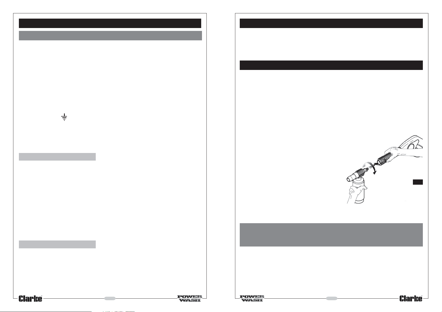
Remove the lance from the trigger/
handle assembly by twisting it clockwise
looking down from the handle end, and
pulling it free. Insert the detergent lance,
push in firmly and twist anticlockwise to
lock in position.
NOTE: It may be necessary to lubricate
the lance spigot when new to assist when
attaching to the handle.
With the container filled with detergent, screw it on to the detergent lance
ensuring the plastic pickup tube is in place.
IMPORTANT:
ALWAYS read and comply with the manufacturers instructions
issued with the chemical detergent.
Spray the detergent on to the vehicle, patio etc., and allow it to work
itself into the grime.
To rinse and clean, set the safety latch, replace the detergent lance with
the main lance, release the safety latch and blast off the dirt.
After using the detergent lance, rinse it thoroughly, together with the
container, with clean water. (See Maintenance)
11
Fig.8
Page 7
As soon as you pull the trigger again, water at pressure will be ejected.
PRE- ASSEMBLY CHECKS
WARNING!
Ensure the operator is aware that
when the trigger is pulled, water at
high pressure can cause the lance
to kick fiercely - it should therefore
be held firmly. In addition, care must
be taken to ensure that the nozzle
is NOT aimed at an area where the
water jet will cause damage. i.e.
away from people, animals,
windows - greenhouses etc., and
be aware that splash back could
also cause damage if the jet is
trained on a nearby wall etc.
As explained above, whenever you release the trigger, the bypass valve
will operate, allowing the motor to continue to run whilst water is not
delivered at the nozzle. IMPORTANT! To avoid overheating, you should never
allow this condition to exist for longer that 1 minute or so.
To turn the machine OFF, press the OFF button (see Fig. 5), THEN........
ALWAYS press the trigger, to ensure there is no pressure in the hose.
Get into the habit of pressing the trigger again BEFORE disconnecting
the hose from the machine.
In the event that you switch the machine OFF, but intend to continue with
its use after a few minutes or so, DO NOT depress the trigger, but set the
safety latch to prevent it from being accidentally pulled. This will ease
and assist the subsequent restarting of the motor as pressures will remain
equalised on either side of the pump, thereby reducing the load on the
motor when restarting.
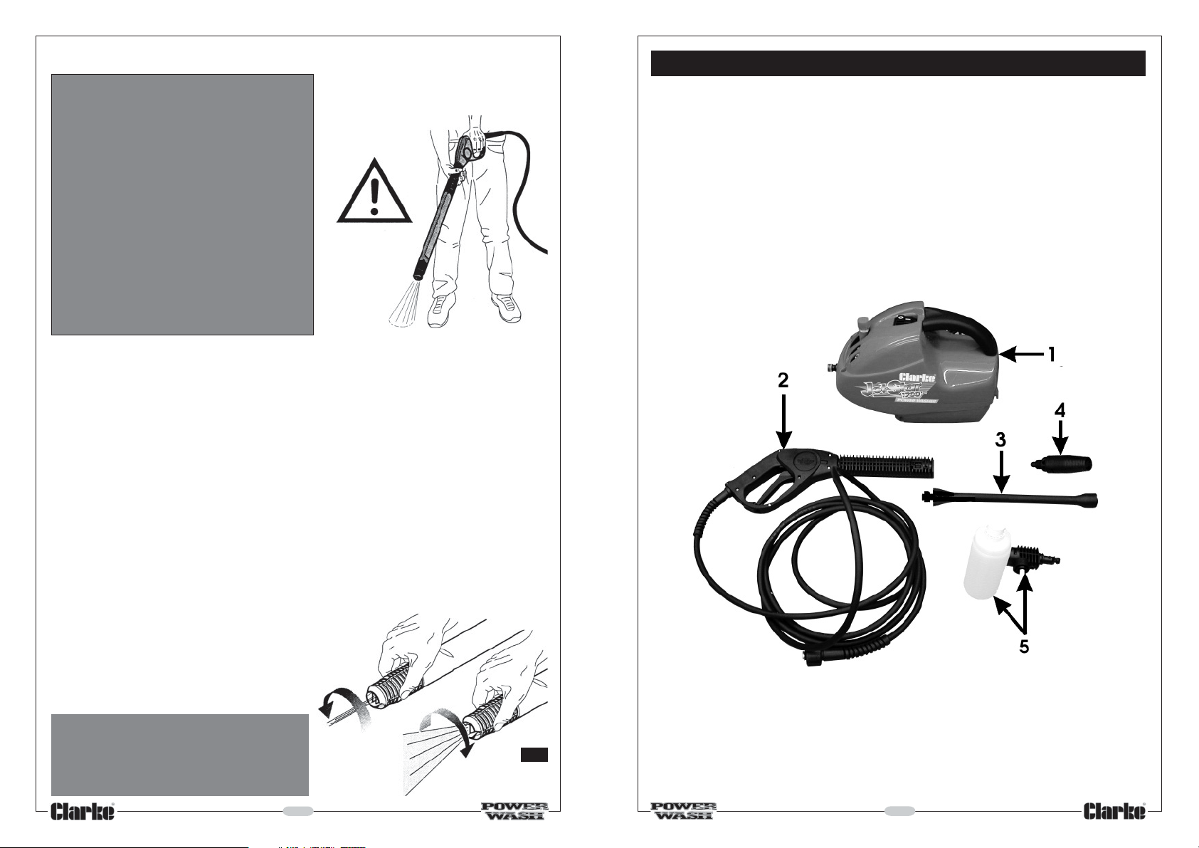
Before assembling your new Jetstar 1700 Powerwasher, check to ensure
that all parts listed below are included.
Item 1 Powerwasher with cable and plug
Item 2 Trigger/Handle assembly with high pressure hose
Item 3 Lance Extension
Item 4 Nozzle assembly
Item 5 Detergent/foam lance with container
A high pressure pencil jet or fan spray
may be selected by twisting the nozzle
as shown in Fig.7.
NEVER attempt to run the
machine with the water
supply disconnected, or
turned off
10
Please check to ensure that no damage was suffered in transit. Should any
damage be apparent, you should notify your Clarke dealer immediately.
Fig.7
7
Page 8
ASSEMBLY AND PREPARATION FOR USE.
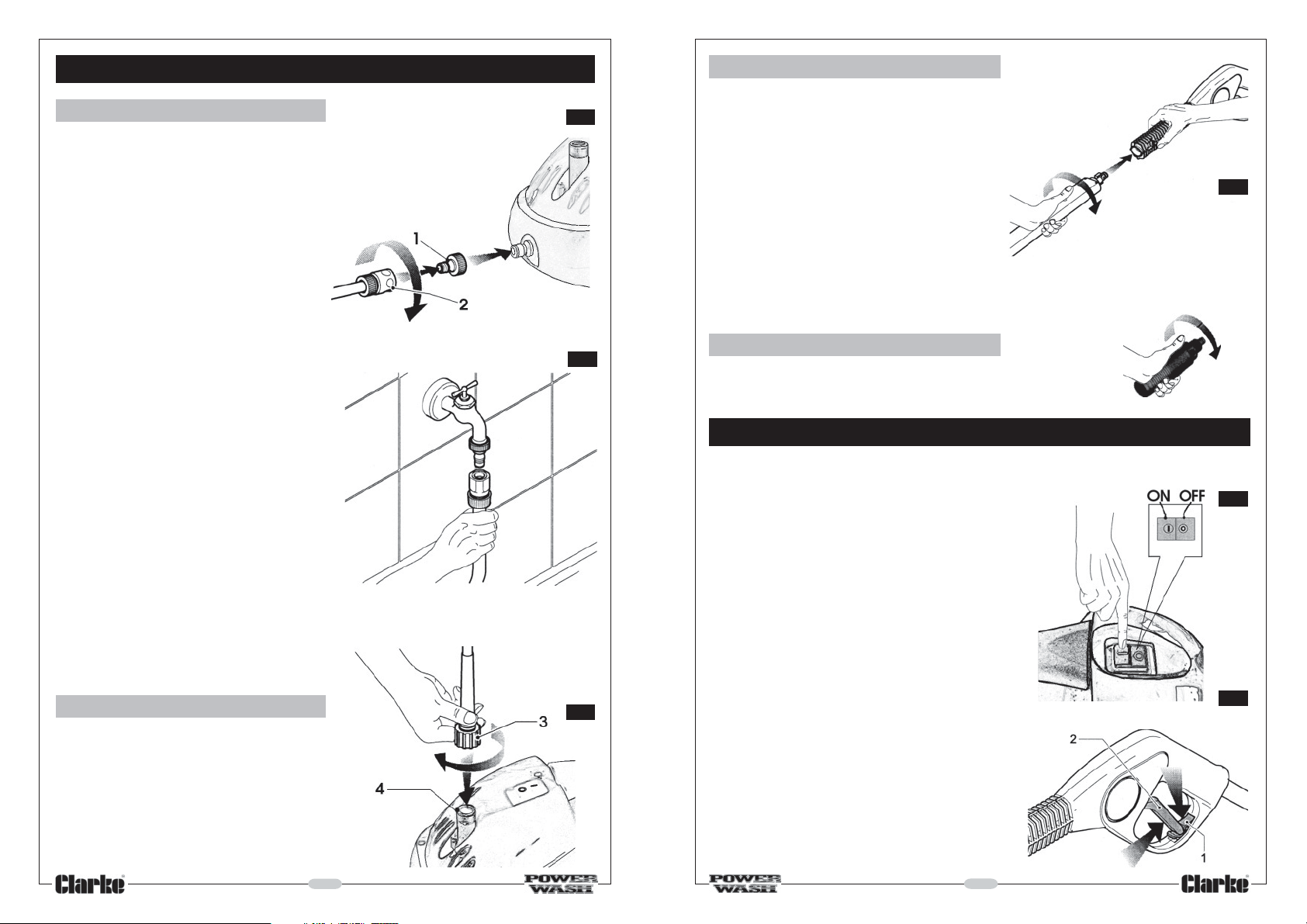
A. Water Supply Hose
Remove the temporary travel cap from
the threaded inlet port and screw on the
inlet hose adapter (1), ensuring the filter,
within the port and sealing ring within the
adapter are in both in place
Attach a suitable hose to the inlet hose
adapter, using a worm drive clip, or more
commonly used, a Quick Fit Coupling
as shown at 2, Fig 1.
NOTE:
1. Use a good quality hose of at
least 1/2" (13 mm) diameter.
2. Hose, worm drive clips, Quick Fit
Couplings are not supplied but
are available from all good DIY,
Hardware and Garden Supplies
Stores.
Secure the other end of the hose to
your tap using a suitable tap adaptor
(not supplied) CLEAN, cold or hot
water (up to 40°C) can be used.
NOTE:
In some areas, it may be necessary to
ensure that you comply with local
bylaws concerning the use of water
from the mains supply, and the disposal
of possibly contaminated water.
B. High Pressure Hose
Remove the plastic travel cap from
the threaded high pressure outlet (4,
Fig.3), then insert and push home the
high pressure hose into the
connector.
Tighten the ring nut (3, Fig. 3), by hand
taking care not to overtighten.
8
Fig.1
Fig.2
Fig.3
B. Lance
At the opposite end to the nozzle is a
spigot with two integral lugs, and a
rubber O-ring. Ensure the O-ring is in
place and in good condition.
Insert the spigot end of the nozzle into the
handle/lance assembly. Push home firmly
Fig.4
to lock it in position. Twist anticlockwise
looking down from the handle end. DO
NOT attempt to disassemble the lance/
handle assembly.
NOTE: When new, the lance may be a tight fit and a little lubrication, with
vaseline or similar, will assist when joining the parts together.
C. Nozzle
The nozzle simply screws into the end of the lance.
OPERATION
Make certain the ON/OFF switch is set in the OFF position, see Fig. 5.
Connect the plug to the mains supply,
preferably via a Residual Current Device.
Turn the water tap fully on.
When starting, it is IMPORTANT that you
adopt the following procedure:
In order to ease the starting process, and to
prevent the possibility of blown fuses, pull the
trigger on the lance - it may be necessary to
release the safety latch in order to do so (1,
Fig.6), and hold the trigger in that position
whilst switching the motor ON and allowing
the pump to develop full pressure.
You may release the trigger once full pressure
is developed. When you do so, a bypass
valve will operate, and the motor will
continue to run, but water will not be
delivered at the nozzle.
9
Fig.5
Fig.6
 Loading...