

Page 1

SUBMERSIBLE PUMPS
HSE RANGE
OPERATING & MAINTENANCE
INSTRUCTIONS
GC0514
Page 2
INTRODUCTION
Thank you for purchasing this CLARKE submersible pump.
Before attempting to use the pump, please read this manual thoroughly and
follow the instructions carefully. In doing so you will ensure the safety of
yourself and that of others around you, and you can look forward to the
submersible pump giving you long and satisfactory service.
GUARANTEE
This product is guaranteed against faulty manufacture for a period of 12
months from the date of purchase. Please keep your receipt which will be
required as proof of purchase.
This guarantee is invalid if the product is found to have been abused or
tampered with in any way, or not used for the purpose for which it was
intended.
Faulty goods should be returned to their place of purchase, no product can
be returned to us without prior permission.
This guarantee does not affect your statutory rights.
ENVIRONMENTAL PROTECTION & RECYCLING
Do not dispose of this product with general household waste. It must
be disposed of according to the laws governing Waste Electrical and
Electronic Equipment, at a recognised disposal facility. Any old tools,
accessories and packaging should be sorted and disposed of in an
environmentally appropriate manner.
Through purchase of this product, the customer is taking on the obligation to
deal with the WEEE in accordance with the WEEE regulations in relation to the
treatment, recycling & recovery and environmentally sound disposal of the
WEEE.
In effect, this means that this product must not be disposed of with general
household waste. It must be disposed of according to the laws governing
Waste Electrical and Electronic Equipment (WEEE) at a recognised disposal
facility.
2
Page 3

TABLE OF CONTENTS
INTRODUCTION .................................................................................. 2
GUARANTEE ........................................................................................ 2
ENVIRONMENTAL PROTECTION .........................................................2
SPARES & SERVICING CONTACTS ......................................................2
TABLE OF CONTENTS .......................................................................... 3
PUMP SAFETY INSTRUCTIONS ............................................................. 4
ELECTRICAL CONNECTIONS .............................................................. 5
OVERVIEW .......................................................................................... 7
OPERATION .........................................................................................9
CLEANING & MAINTENANCE.............................................................11
FAULT FINDING .................................................................................... 12
PARTS LISTS & SPARES DIAGRAMS ...................................................... 13
TECHNICAL SPECIFICATIONS .............................................................16
DECLARATIONS OF CONFORMITY .....................................................17
3
Page 4

PUMP SAFETY INSTRUCTIONS
1. Only use the pump in the manner and for the functions described in these
instructions.
2. These pumps are designed to pump water only. Never use for pumping
flammable liquids or corrosive chemicals of any kind.
3. Never allow the pump to run dry. Switch the pump OFF immediately the
task is completed.
4. An approved Residual Current Device (RCD) must be used when pumping
from ponds or swimming pools.
5. The submersible pump may only be used for pumping water from a
swimming pool when there is no person or animal in the pool.
6. Do not attempt to carry out any repairs on the pump until it is unplugged
from the power supply.
7. Always lift the pump using the handle with rope or chain attached if
necessary. Never lift or carry the pump by the power cable or by the float
switch cable.
8. Always disconnect the pump from the electrical supply before placing it
into, or removing from the water, and before any cleaning or
maintenance of the pump.
9. Remember, the operator or user is responsible for accidents or hazards
occurring to other people or their property.
10. Do not install the pump on sand, silt or mud which is likely to shift or
collapse.
11. If the electrical cable becomes damaged, it must be replaced, - not
repaired.
12. Keep the work area well lit. Dark areas invite accidents.
13. Do not over-reach. Keep your proper footing and balance at all times
when handling the pump in waterlogged areas.
14. Store the pump out of the reach of children and do not allow persons
unfamiliar with these instructions to operate the pump.
15. Do not abuse the electrical cable. Never use the cable for pulling or
unplugging the pump Damaged or tangled cables increase the risk of
electric shock.
16. Check the pump for damage before use. Any damaged part should be
inspected to ensure that it will operate properly and perform its intended
function. Any damage should be properly repaired or the part replaced.
If in doubt, DO NOT use the appliance. Consult your local dealer.
17. When operating outdoors, use an extension cable suitable for outdoor
use. Using the correct cable reduces the risk of electric shock.
4
Page 5

18. Always use an approved cable extension suitable for the power rating of
this pump (see specifications), the conductor size should also be at least
the same size as that on the pump, or larger. When using a cable reel,
always unwind the cable completely.
19. Keep children and bystanders away while operating the pump.
Additionally, please keep these instructions in a safe place for future reference.
ELECTRICAL CONNECTIONS
All models EXCEPT HSE301A, 361A & HSEC651A should have their mains lead
connected to a standard 230 volt (50Hz) electrical supply through an
approved plug or a suitably fused isolator switch. We recommend that these
pumps be fitted with a Residual Current Device (RCD).
NOTE: This is mandatory when pump is used for pumping swimming pools.
Models HSE301, 361 & HSEC651A must be connected to a protected 110V
supply, through a suitably approved connector. On no account must a 230V,
13amp plug be used.
NOTE: If a portable 110V transformer is used, make sure it has a rated
capacity sufficient to take the load of the pump.
In the event that the pump is hard-wired into the electrical system, it must be
carried out in accordance with IEE regulations.
If used for draining swimming pools or ponds, the pump MUST be fitted with a
Residual Current Device (RCD), with a rated residual operating current of no
greater than 30mA.
WARNING: THIS APPLIANCE MUST BE EARTHED
IMPORTANT: The wires in the mains lead are coloured in accordance with the
following code:
Green & Yellow - Earth
Blue - Neutral
Brown - Live
As the colours of the flexible cable of this appliance may not correspond with
the coloured markings identifying terminals in your plug proceed as follows:
• Connect GREEN & YELLOW coloured cord to plug terminal marked
with a letter “E” or Earth symbol “
& YELLOW.
• Connect BROWN cord to terminal marked with a letter “L” or
coloured RED.
• Connect BLUE cord to terminal marked with a letter “N” or coloured
BLACK.
” or coloured GREEN or GREEN
5
Page 6

FUSE RATING
The fuse in the plug for this appliance must be rated according to the
Technical Specification on page 16.
If this product is fitted with a plug which is moulded onto the electrical cable
(i.e. non-rewirable) please note:
1. The plug must be thrown away if it is cut from the cable. There is a danger
of electric shock if it is subsequently inserted into a socket outlet.
2. Never use the plug without the fuse cover fitted.
3. Replacement fuse covers can be obtained from your local dealer or most
electrical outlets.
4. The fuse in the plug must be replaced with one of the same rating and this
replacement must be ASTA approved to BS1362.
IMPORTANT: If in doubt, consult a qualified electrician.
6
Page 7
OVERVIEW
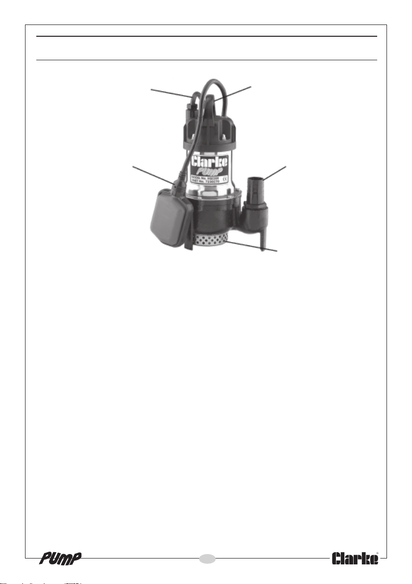
MAINS CABLE
FLOAT
SWITCH
LIFTING HANDLE
DISCHARGE
OUTLET
STRAINER
PROTECTED
INLET
The CLARKE HSE range of submersible pumps are of rugged and durable
construction, designed for long lasting continuous operation. They are
suitable for discharging pools, ponds, fountains, pits and any waste water
drainage. They can handle foul water containing sewage or other
suspended material including sand up to a maximum of 3kg/m
amount stated in the specifications for each model. They may be used for
pumping water, (including seawater) or water containing small solids in
suspension with particle sizes of up to 6-10mm in diameter, dependant upon
the size of pump. The pumps are not suitable for handling inflammable,
corrosive, explosive or dangerous liquids.
The range includes models 130, 200, 300/301, 360/361 and 650/651 as
itemised in the Technical Specification on page 16.
The HSEC650 & HSEC651A are fitted with a tungsten carbide cutter, and is
specially suited for heavily polluted water and waste solids, such as sewage,
light slurry, factory waste etc. The HSE200 is fitted with a strainer to prevent the
ingress of foreign matter.
Float switches are fitted to those models bearing an ‘A’ suffix, meaning the
pump will stop and restart automatically as the surrounding water level
changes. This makes them suitable for permanent or semi-permanent
installations, eg. installations where it is necessary to maintain a water at a
particular level without an operator in attendance.
3
to an
7
Page 8

As the water level rises, the switch will float and start the pump. As the water
level falls, so will the float switch, until it stops the pump. Float switches are
factory set to provide the correct ON-OFF switching mode.
• It is not recommended that these pumps be used for pumping
drinking water, as there is a remote possibility of water
contamination due to leakage of pump lubricant should the pump
malfunction or the oil seal become damaged.
All HSE pumps are provided with a thermal overload cut-out, so that in the
event the pump becomes overheated (due to becoming blocked etc.) the
pump will shut off automatically
thermal overload will cool down and re-set and the pump can be re-started.
. When the blockage has been cleared, the
8
Page 9
OPERATION
CONNECTION AND LOCATION
1. Place the pump in a vertical position resting on a firm, flat surface. If this is
not available, sit the pump on timber or house bricks, but ensure they are
not likely to collapse. Never install the pump on sand, silt, mud or ground
that is likely to collapse.
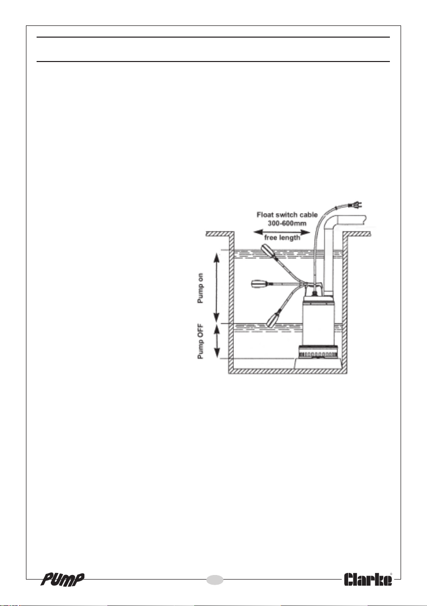
Automatic versions should only be placed in a sump which is large
enough not to restrict the movement of the float switch. It is advisable to
use a strainer when using the pump as a sump pump.
2. Keep the pump clear of
any sediment by standing
it on a platform or brick or
suspending from a rope
attached to the handle if
the pump is to be used
where there may be silt or
mud etc (e.g. garden
ponds).
3. Connect the outlet to the
largest diameter hose
available, as any
restrictions will reduce
capacity and put further
strain on the motor. The
outlet hose diameter for
each HSE pump is given in
the Technical
Specification on page 16.
4. Ensure that the hose diameter is equal to or greater than the diameter of
the pump outlet if a long run of discharge hose is being used.
5. Ensure the float has sufficient room to operate correctly if used in a
confined space such as a shaft or sump.
Note: When the pump is being used in a permanent or semi-permanent
installation, a check valve must be fitted in the delivery hose.
Suitable hoses are available from your Clarke dealer.
USING THE PUMP
1. Take all necessary precautions as described on page 4 before plugging in
the pump and switching ON. Where the pump is an automatic unit fitted
with a float switch, the pump will only run where there is sufficient depth of
water for the float to rise and activate the pump.
9
Page 10
2. If the water is likely to freeze, the pump must be run continuously,
otherwise the pump must be removed from the water and stored in a frost
free location.
3. Never run the pump dry. Never run the pump with the body exposed for
more than 10 minutes.
4. When the water has been pumped out, disconnect from the power
supply. Avoid running the pump continuously.
AUTOMATIC THERMAL OVERLOAD
These pumps are fitted with automatic thermal overload protection. If the
pump overheats due to an obstruction in the pump, or pumping warm water
for example, it will shut off automatically. Switch the pump OFF and
disconnect from the mains supply. Check for blockages and allow the motor
to cool (at least 5 minutes) before attempting to restart, by which time the
cut-out will have reset.
ACCESSORIES
A wide range of accessories is available from your nearest CLARKE dealer, for
further information, contact your nearest dealer, or telephone CLARKE
International Sales department on 01992 565300.
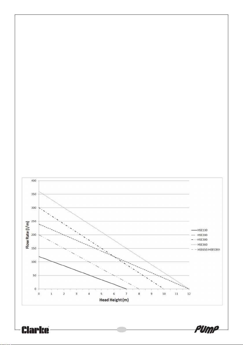
PUMP PERFORMANCE
10
Page 11

CLEANING & MAINTENANCE
WARNING: MAKE SURE THAT THE PUMP IS DISCONNECTED FROM THE
MAINS SUPPLY BEFORE CLEANING, OR PERFORMING ANY
MAINTENANCE.
• This pump should require no maintenance other than regular
cleaning. If the pump starts to show signs of wear or damage,
contact your CLARKE dealer for advice.
• Do not use the pump if there is any damage to the mains power
cable, or to the float switch or it’s connecting cable.
• Check pump installation regularly to ensure the base inlet is clear of
leaves or other debris.
• Do not attempt to repair the pump yourself, as you may damage
the waterproof seal and invalidate your guarantee. Repairs must be
carried out by your CLARKE dealer, or contact the CLARKE Service
Department on 020 8988 7400.
If using this pump to empty a garden pond, please note that there is a small
quantity of oil in the pump seal. If the pump or seal is damaged, possibly
caused by running the pump dry, oil may leak out, and appear as a film on
the surface of the water. The oil must be cleared to prevent any possible
harm to pond life. Disconnect the pump from the electrical supply, remove it
from the pond and clear the oil, then contact your CLARKE dealer for advice.
11
Page 12

FAULT FINDING
MELBORP SESUACELBISSOP
.nurton
pmuP
.potston
d
.spots
tubsnurpmuP
tspmup
.stra
arofsnurrotoM
neht,emittrohs
seod&smuhpmuP
vobaehtllafI
etulovrorellepmI
seodtubsnurpmuP
.retawreviledton
htnaelc
spmup&snur
seodtubpmustuo
.esac
llamsaylnosrevile
.retawfotnuoma
tiucricroswolbesuF
nehwspirtrekaerb
am
.tuo
.pmusniyleerf
iggulpnudna
upniselohtelnI
vrorellepmI
aerevoba
nsahpmusnilevelretaW
fonoitceridnitniopdluohs
.wolf
.tuonaelc&pmupevomeR
.sgninepodnareniartse
.pmupehtfognittifegrahcsidehtegnahc
tiwecalpeR.hctiwstaolfevitcefeD
.pmupehtfognittifegrahcsidehtegnahc
nepoetulovrorellepmI
.sgninepoehttuonaelc
.sgninepodnareniartsehtnaelc
.naelcdnapmupevomeR
.deggolcsirollepmipmuP
meR.daolrevodnaylwolsnurotrotom
.evitcefedebyamrotatsrotoM
.naelcdnapmupevomeR
.nitucsahhctiwstaolF.snos
.esoolrodenrubsiesufroffosirekaerbtiucriceniL
.levelno-nrutdehcaerto
.)retawfonisabaniyleerfetarepodluohstI(.kcutssitaolF
.evitcefedebdluocrotom,KOerae
evlavnoworrA.sdrawkcabdellatsnisi)dettiffi(evlavkcehC
.desolcebyam)desufi(evlavffo-tuhsegrahcsiD
.deggolcyllaitraproylluferasgninepo
itnevriadeggolcrofkcehC.gniggulpnudna
.hctiwswenh
.hctiwswenhtiwecalpeR.hctiwsrewopevitcefeD
napmupevomeR.daolrevodnaylwolsnurotrotom
.naelcdnapmupevomeR.deggolcyllaitrap
nigniggulpybsemitlarevespotsdnatratS.dekcol-riasipmuP
.gnisacpmupn
dnapmupevomeR.deggolceraesabehttaselohtelnI
roecnatsidecudeR.hgihootsiecnatsidgnipmuplacitreV
setarepotaolftahteruseB.noitisopPUehtnikcutssitaolF
nigniggulpybsemitlarevespotsdnatratS.dekcol-riasipmuP
pmupnitnevdeggolcrofkcehC.elbacgn
roecnatsidecudeR.hgihootsiecnatsidgnipmuplacitreV
napmupevomeR.deggolceraesabehttaselohtelnI
d
.deggolcyllaitraproylluferasgni
gnisuac,cte,rat,tniaphtiwdeggolcyllaitrapsirellepmipmuP
.naelcd
rekaerbtiucricroezisesuF.evitcefedebyamrotatsrotoM
roylluferagninepoetulovrorellepmI.llamsooteby
dnapmupevomeR.deggolceraesabpm
gnisuac,tniaprorathtiwdeggolcyllaitrapsirellepmipmuP
naelcdnapmupevo
.deggolcyllaitraproylluferasgninepoetulo
ehtfoenooteuddetareposahtuo-tucdaolrevolamrehT
12
Page 13
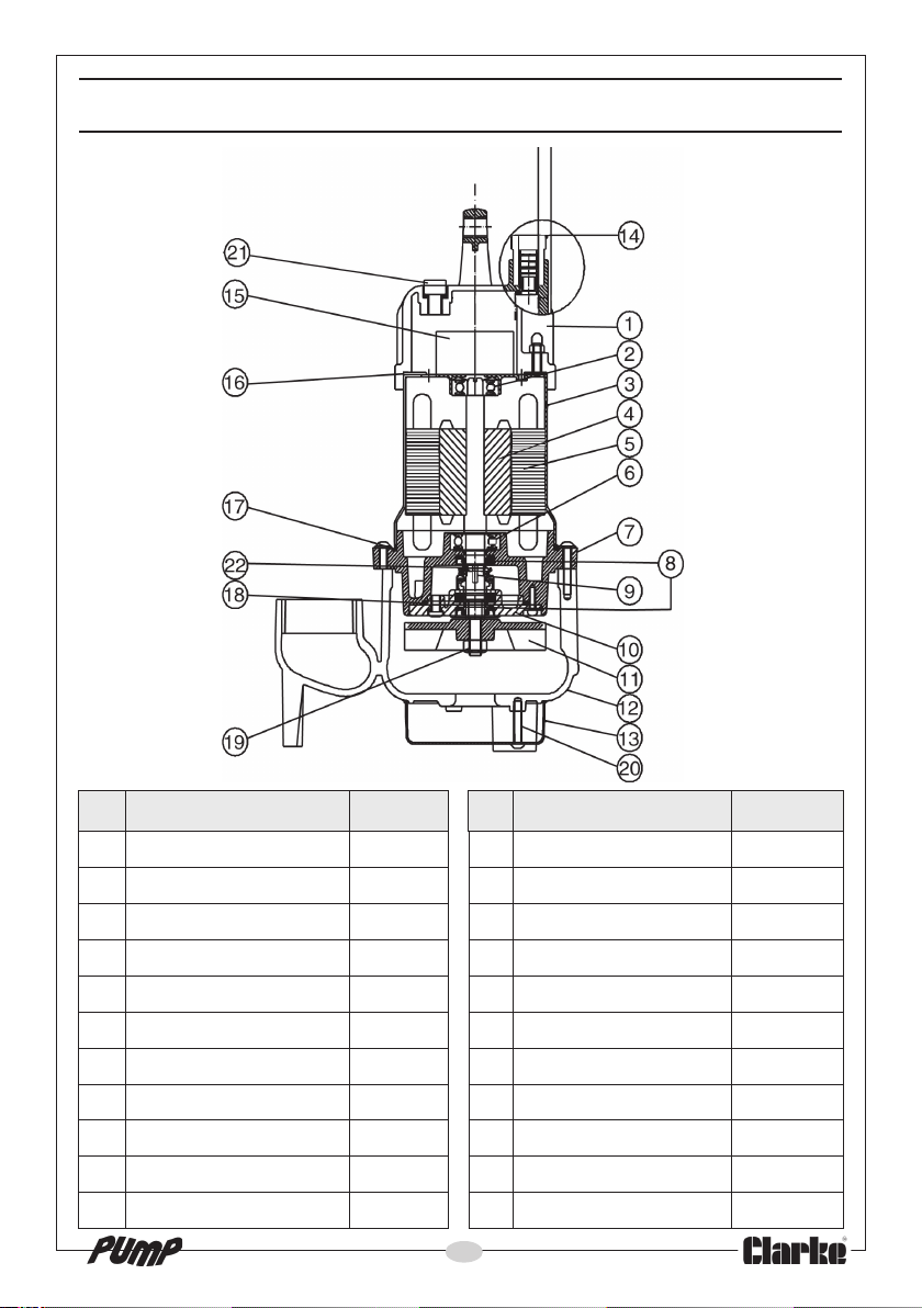
PARTS LIST & DIAGRAM HSE130
ON NOITPIRCSED
1revoCpoT10031GH21gnisaCpmuP21031GH
2gniraeBreppU20031GH31reniartS31031GH
3gnisuoHrotoM30031GH41elbaCrewoP41031GH
4tfahS4
5rotatS50031GH61gnikcaPpaC61031GH
6gniraeBrewoL60031GH71gniR-O71031GH
7etalPlaeS70031GH81gniR-O81
8laeSliO80031GH91tuN91031GH
9laeSlacinahceM90031GH02wercSgnitteS02031GH
01revoClaeS01031GH12gulPni-wercS12031GH
11r
ellepmI11031GH22gniRgniniateR22031GH
ONTRAP
0031GH51roticapaC51031GH
ON NOITPIRCSED
13
ONTRAP
031GH
Page 14
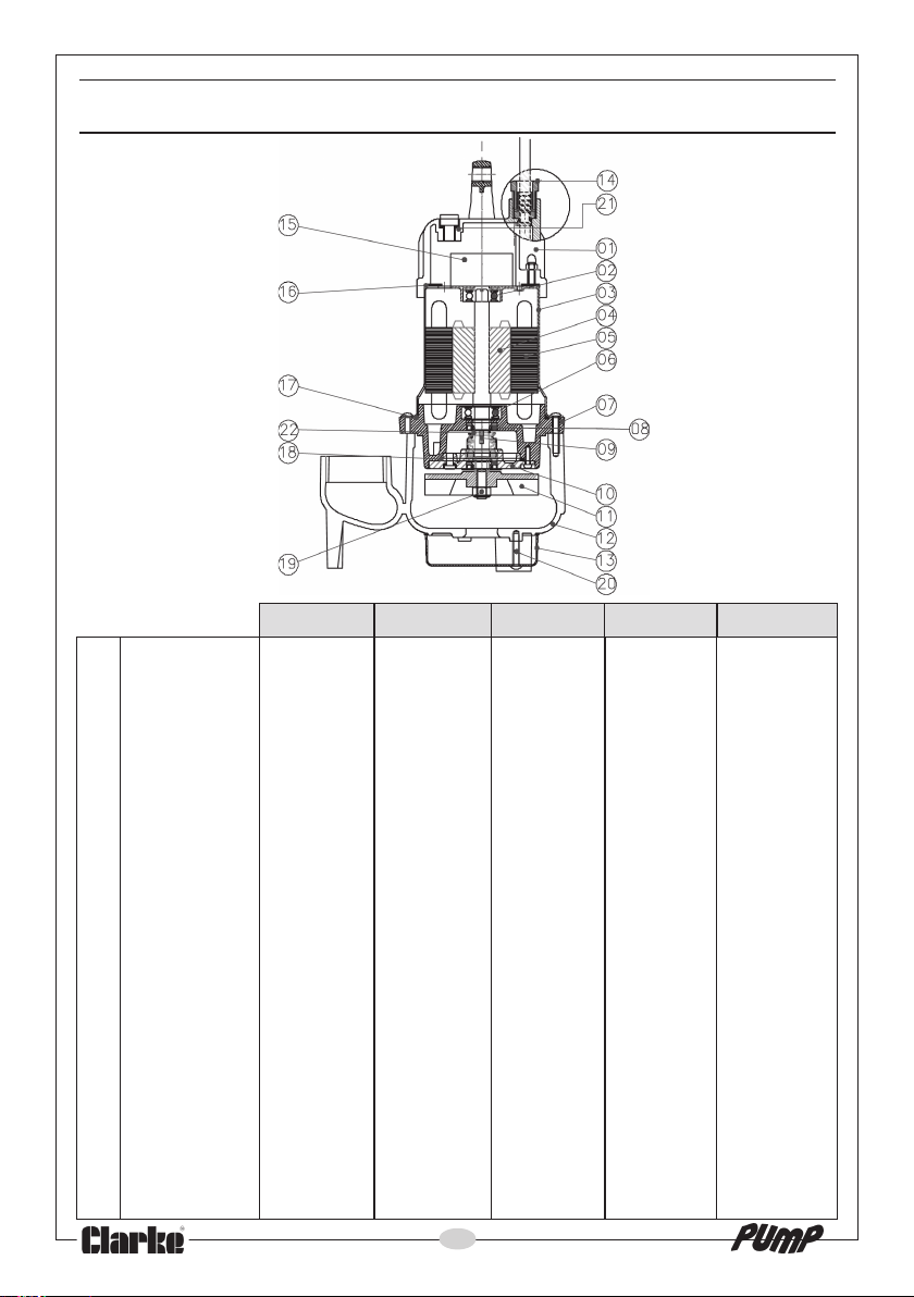
PARTS LIST & DIAGRAM:- HSE200/300/301/360
HSE200 HSE300 HSE301 HSE360 HSE361
1 Top Cover HG20001 HG30001 HG30101 HG36001 HG36101
2 Upper Bearing HG20002 HG30002 HG30102 HG36002 HG36102
3 Motor Housing HG20003 HG30003 HG30103 HG36003 HG36103
4 Shaft HG20004 HG30004 HG30104 HG36004 HG36104
5 Stator HG20005 HG30005 HG30105 HG36005 HG36105
6 Lower Bearing HG20006 HG30006 HG30106 HG36006 HG36106
7 Seal Plate HG20007 HG30007 HG30107 HG36007 HG36107
8 Oil Seal HG20008 HG30008 HG30108 HG36008 HG36108
9 Mech. Seal HG20009 HG30009 HG30109 HG36009 HG36109
10 Seal Cover HG20010 HG30010 HG30110 HG36010 HG36110
11 Impeller HG20011 HG30011 HG30111 HG36011 HG36111
12 Pump Casing HG20012 HG30012 HG30112 HG36012 HG36112
13 Strainer HG20013 HG30013 HG30113 HG36013 HG36113
14 Power Cable HG20014 HG30014 HG30114 HG36014 HG36114
15 Capacitor HG20015 HG30015 HG30115 HG36015 HG36115
16 Cap Packing HG20016 HG30016 HG30116 HG36016 HG36116
17 O-ring HG20017 HG30017 HG30117 HG36017 HG36117
18 O-ring HG20018 HG30018 HG30118 HG36018 HG36118
19 Nut HG20019 HG30019 HG30119 HG36019 HG36119
20 Setting Screw HG20020 HG30020 HG30120 HG36020 HG36120
21 Screw-in Plug HG20021 HG30021 HG30121 HG36021 HG36121
22 Retaining Ring HG20022 HG30022 HG30122 HG36022 HG36122
14
Page 15
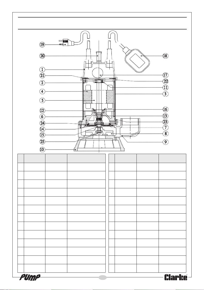
PARTS LIST & DIAGRAM:- HSEC650A/651A
oN
110A056GH10A156GHrevoCreppU4141A056GH41A156GHlaeSliO
220A056GH20A156GHrevoCgniraeBpoT5151A056GH51A156GHev
330A056GH30A156GHgnisuoHrotoM6161A056GH61A156GHgniRkcoL
440A056GH40A156GHrotatS7171A056GH71A156GHroticapaC
550A056
660A056GH60A156GHrevoClaeS9191A056GH91A156GHelbaCrewoP
770A056GH70A156GHet
880A056GH80A156GHrellepmI1212A056GH12A156GHgnikcaP
990A056GH90A156GHgnisaCpmuP2222A056G
0101A056GH01A156GHreniartS3232A056GH32A156GHgnir-O
1111A056GH11A156GHsgniraeBpoT4242A056GH42A156GHgnir-
2121A056GH21A156GHgniraeBrewoL5252A056GH52A156GHtuN
3131A056GH31A156GHlaeShceMelbuoD
056CESH A156CESH NOITPIRCSED
GH50A156GHrotoR8181A056GH81A156GHhctiwStaolF
alPlaeS0202A056GH02A156GHeldnaH
oN
H22A156GHgnir-O
15
056CESH A156CESH NOITPIRCSED
eelS
O
Page 16
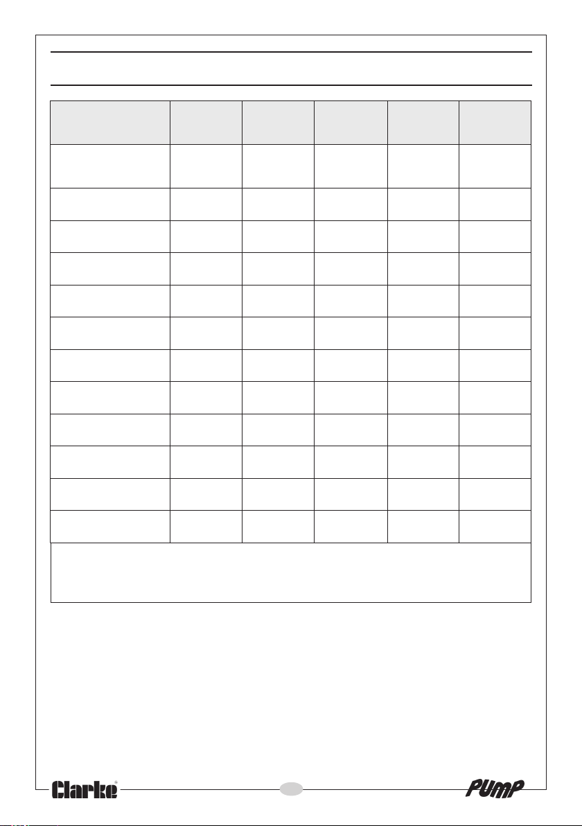
TECHNICAL SPECIFICATIONS
ledoM
ontrapEKRALC
aiDteltuO
)sehcni/mm(
egatloVrotoMzh05/V032zh05/V032
xam@egattaWrotoM
etarwolf
)spma(gnitaResuF55313131
lbaC0101010101
)m(htgnele
gnitaRPI86PI86PI86PI86PI86PI
)m(daeH.xaM7801215.9
)nim/L(etaRwolF.xaM041002003063092
HxWxLsnoisnemiD
)mm(
)gk(thgieW71.8212171
031ESH
A031ESH
5120327
7120327
"4/1-1/23"2/1-1/83"2/05"2/05"2/05
382024027069566
1x503413x531x791053x141x522563x141x522024x081x042
331x88
A002ESH
0720327
003ESH
A003ESH
A103ESH
5520327
0620327
5620327
zh05/V032
*zh05/V011
063ESH
A063ESH
A163ESH
5720327
0820327
5820327
h05/V032
z
*zh05/V011
A056CESH
A156CESH
0920327
0327
592
zh05/V032
*zH05/V011
)m(htpeDmumixaM010101015
03* nierehdeniatnocsnoitacificeps&sliatedtahtetonesaelP
gnahc
.etalp
.ylnoledomA156&A163,A1
irpotgniogfoemitehttatcerrocera
16
otthgirehtevreserlanoitanretnIEKRALC,revewoH.tn
atadenihcamehttlusnocsyawlA.ecitonroirptuohtiwemitynatasnoitacificepse
Page 17

DECLARATION OF CONFORMITY
17
Page 18

DECLARATION OF CONFORMITY
18
Page 19

DECLARATION OF CONFORMITY
19
Page 20

 Loading...