

Page 1
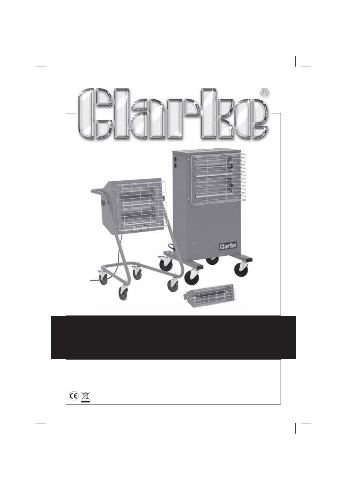
INFRA RED HEATERS
INFRA RED HEATERS
Models
DEVIL160 • DEVIL360P • DEVIL365P
OPERATING & MAINTENANCE
INSTRUCTIONS
0705
Page 2

Thank you for purchasing this Clarke Infra Red Heater.
Before attempting to operate the unit please read this instruction leaflet and carefully
follow all directions given. By doing so you will ensure safe operation of the unit and you
can also look forward to it providing you with long and trouble free service.
GUARANTEE
This CLARKE product is guaranteed against faults in manufacture for 12 months
from purchase date. Please keep your receipt as proof of purchase.
This guarantee is invalid if the product has been found to have been abused in
any way, or not used for the purpose for which it was intended, or to have been
tampered with in any way. The reason for return must be clearly stated.
This guarantee does not affect your statutory rights.
SAFETY PRECAUTIONS
• This heater is for INDOOR USE ONLY.
• ALWAYS disconnect from the mains supply before moving or performing any
maintenance tasks.
• ALWAYS use in an upright position ONLY.
• Inspect the mains cable regularly for signs of damage. DO NOT use if it is
damaged, and ALWAYS keep it away from the source of heat.
• Ensure the wall mountings, where used, are perfectly sound at all times.
• DO NOT install the heater BELOW an electrical outlet.
• NEVER switch ON the heater when the guard is removed.
• NEVER mount or locate the heater near combustible materials such as
curtains, furniture etc. Allow at least 2 metres distance.
• DO NOT use this heater in a bathroom or shower room.
• DO NOT use this heater in greenhouses or construction areas.
• DO NOT mount or locate the heater close to an adjacent wall or ceiling...allow
a distance of at least 1 metre from a wall and 10” from a ceiling.
• NEVER cover the heater, or block any of the vents.
• DO NOT use if the IR Halogen Tubes are damaged or broken.
• NEVER touch the heater for at least 15 minutes after it is switched off.
• DO NOT use this heater in the vicinity of a swimming pool.
• NEVER touch the lamp - even when cold.
• NEVER use the heater with a timer device as this could be a fire hazard
should the heater move for any reason whilst unnattended.
3
Page 3
ELECTRICAL CONNECTIONS
230 Volt Models
Connect the mains lead to a standard, 230 Volt (50Hz) electrical supply through
an approved 13 amp BS 1363 plug, or a suitably fused isolator switch.
WARNING! THIS APPLIANCE MUST BE EARTHED
IMPORTANT: The wires in the mains lead are coloured in accordance with the
following code:
Green & Yellow ........................ Earth
Blue ............................................ Neutral
Brown ........................................ Live
As the colours of the flexible lead of this appliance may not correspond with the
coloured markings identifying terminals in your plug, or your mains supply, proceed
as follows:
• Connect GREEN & YELLOW coloured cord to plug terminal marked with a
letter “E” or Earth symbol “ ” or coloured GREEN or GREEN & YELLOW.
• Connect BROWN cord to terminal marked with a letter “L” or coloured RED.
• Connect BLUE cord to terminal marked with a letter “N” or coloured BLACK.
Fuse Rating
The fuse in the plug must be replaced with one of the same rating (13 amps) and
this replacement must be ASTA approved to BS1362.
110 Volt Models
These models must be connected to a protected 110V supply, through a suitably
approved connector. On no account must a 230V, 13amp (BS1363) plug be used.
NOTE: If a portable 110V transformer is used, make sure it has a rated capacity
sufficient to take the load of the heater.
In the event that the heater is hard wired into the electrical system, it must be
carried out in accordance with IEE regulations.
WARNING!
IF YOU ARE IN ANY DOUBT ABOUT ELECTRICAL CONNECTIONS, CONSULT
AQUALIFIED ELECTRICIAN.
NEVER ATTEMPT ELECTRICAL REPAIRS YOURSELF.
4
Page 4
ASSEMBLY
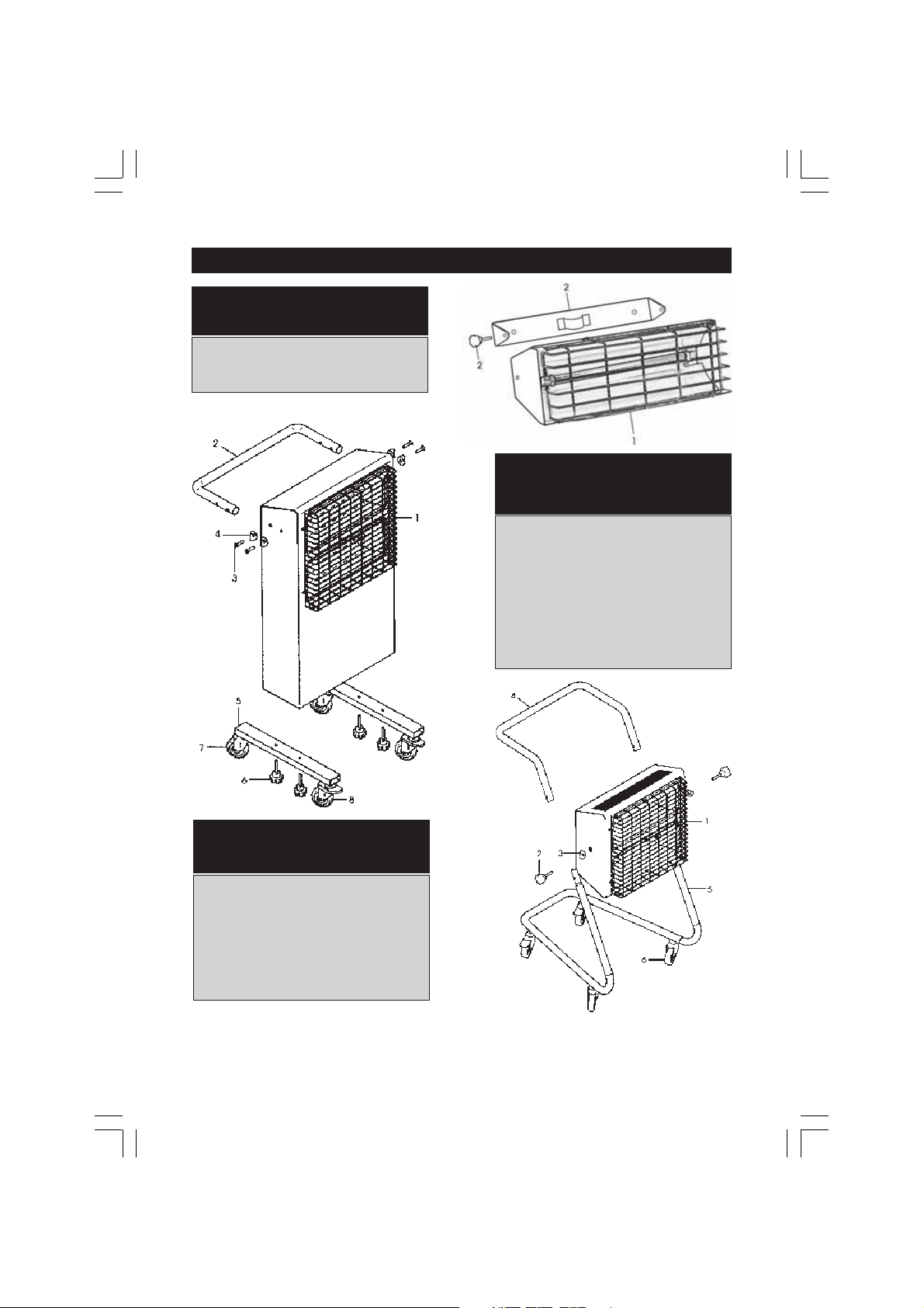
A. Devil 160
First, decide where the heater is to be located, ensuring it is at least 25cm (10”)
from a ceiling and 1 metre from the corner of a room. Also take into account any
furniture, draperies or any other flammable or heat sensitive materials or objects,
ensuring they are at least 2 metres from the heater. Finally ensure a suitable
electrical supply is close to hand (see Safety Precautions).
Mark out the mounting holes on the wall using the mounting bracket as a template. Drill
and plug the wall then screw on the bracket firmly. Mount the heater on the wall bracket
and connect the power cable to the supply (see Electrical Connections). Alternatively
provision is made to mount the bracket on to a support, such as a tripod etc.
IMPORTANT!
When using the heater, the angle of tilt MUST NOT exceed 45 degrees,
as this could lead to the heater overheating. NEVER mount the heater
pointing vertically downwards
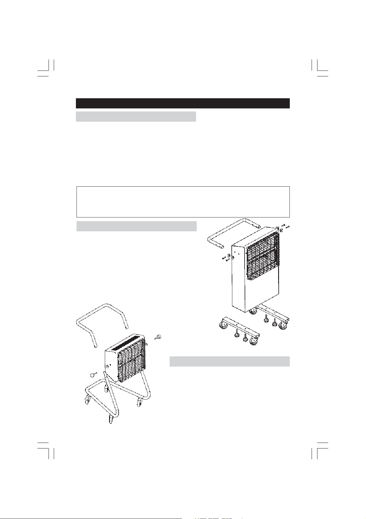
B. Devil 360P
Fit the feet, complete with castors to the
underside of the heater using the four large
knob head screws provided.
Attach the handle to the sides of the main body using
the four countersunk Hex. socket head screws provided
together with the four plastic semi-circular supports
located between the tube and the heater body.
Connect the mains cable to a suitable supply in
accordance with the Electricall Connection
instructions given previously.
C. Devil 365P
Attach the frame to the heater body in the
manner shown in the drawing opposite, with
the t wo plastic saddle supports located between
the tube and the heater body, then connect
the mains cable to a suitable supply in
accordance with the Electrical Connection
instructions given previously.
5
Page 5
MAINTENANCE
Allow the heater to cool down for at least 15 minutes after switching off, before
performing any maintenance tasks.
Periodically.
• Disconnect from the mains supply, remove the guard and wipe the reflectors
with a clean dry cloth. DO NOT use abrasive cleaners. Take care NOT to touch
the tube with your fingers.
• Inspect the mains cable for damage. Heat damage will cause the cable to
stiffen and crack. If this is found, have the cable replaced (refer to your CLARKE
dealer), check cable routing and ensure it is well away from the heat source.
IR Halogen Tube Replacement
Tubes are long lasting and should not need replacing under normal circumstances.
Should this become necessary however, the method of replacement is as follows:
1. Ensure the heater is disconnecterd from the mains supply, then remove the
guard, followed by both side reflectors, each of which is secured with two
screws.
2. Remove the back panel.
3. Disconnect the tube leads from the appropriate switch, by carefully pulling
off the spade connectors.
4. Carefully unclip the tube from its holders at each end, then withdraw the
tube, with leads, from the front of the heater.
5. Replace in the reverse order ensuring you DO NOT touch the tube itself.
Protect the tube with a cloth or paper - your fingers should not come into
contact with it.
IMPORTANT
IF IN ANY DOUBT, ALWAYS CONSULT A QUALIFIED TECHNICIAN. DO NOT
CARRY OUT ANY REPAIRS YOURSELF.
PARTS & SERVICE
PARTS & SERVICE TEL: 020 8988 7400
or e-mail as follows:
PARTS: [email protected]
SERVICE: [email protected]
6
Page 6
SPARE PARTS
DEVIL160
No. Description Part No.
1 Guard AX16001
2 Wall Bracket AX16002
- IR Halogen Tube AX16003
DEVIL360P
No. Description Part No.
1 Guard AX36001
2 Handle AX36002
3 C’sk Screw AX36003
4 Saddle Support AX36004
5 Foot AX36005
6 Securing Knob AX36006
7 Castor AX36007
8 Castor w/Brake AX36008
- IR Halogen Tube AX16003
DEVIL365P
No. Description Part No.
1 Guard AX36001
2 Securing Knob AX36502
3 Saddle Support AX36004
4 Handle AX36504
5 Frame AX36505
6 Castor AX36506
- IR Halogen Tube AX16003
Waste electrical products should not be disposed of with household waste.
Please dispose of at your local recycling facility.
7
 Loading...