

Page 1
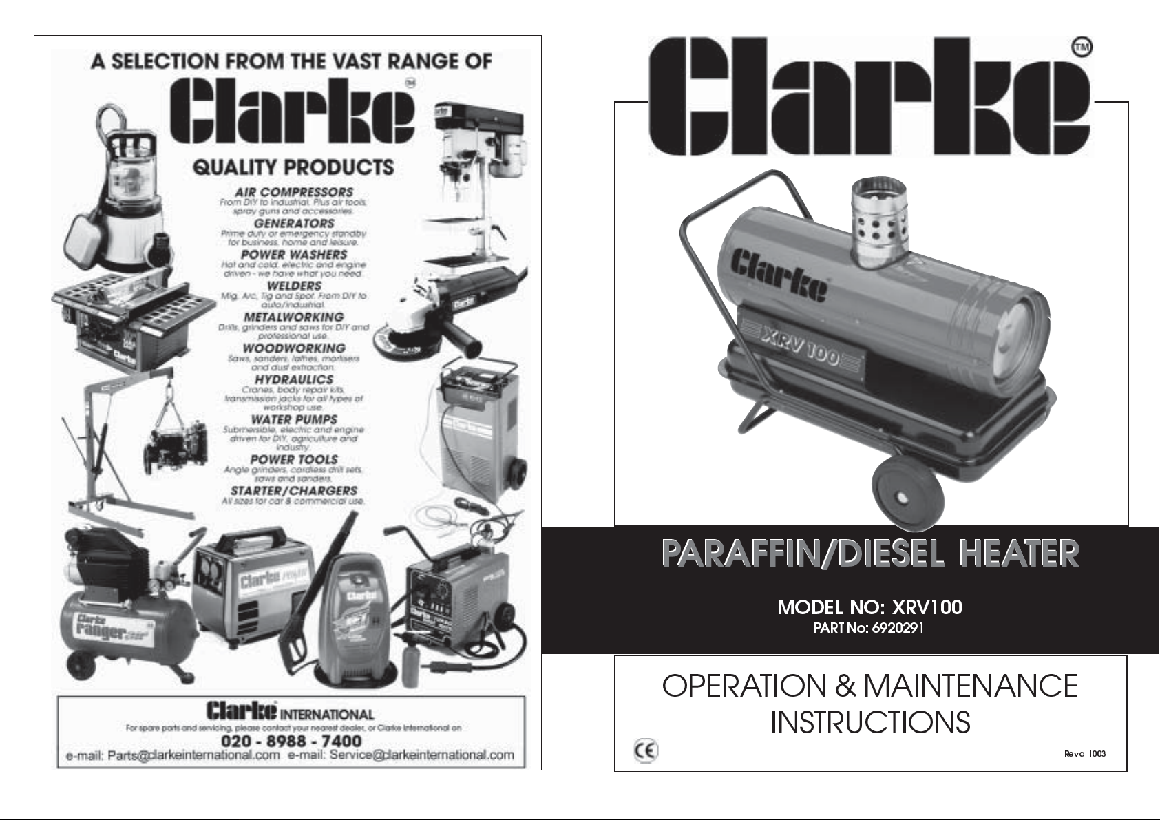
PARAFFIN/DIESEL HEATER
PARAFFIN/DIESEL HEATER
MODEL NO: XRV100
PART No: 6920291
OPERATION & MAINTENANCE
INSTRUCTIONS
Rev a: 1003
Page 2
Thank you for purchasing this CLARKE, Paraffin/Diesel fired Space Heater.
This portable heater is designed for
mechanical equipment, optimum performance will only be achieved if the
correct application and servicing procedures are followed. Please read this
manual thoroughly and follow the instructions carefully before attempting to use
the heater. In doing so you will ensure the safety of yourself and that of others
around you, and you can look forward to it giving you long and reliable service.
industrial applications only
. As with all
Guarantee
This CLARKE product is guaranteed against faulty manufacture for a period of 12
months from the date of purchase. Please keep your receipt as proof of
purchase. This guarantee is invalid if the product is found to have been abused or
tampered with in any way, or not used for the purpose for which it was intended.
Faulty goods should be returned to their place of purchase, no product can be
returned to us without prior permission. This guarantee does not effect your
statutory rights.
Contents
Safety Precautions ......................................................................... 2
Electrical Connections................................................................... 3
Assembly ......................................................................................... 4
Installation ....................................................................................... 5
Operation..................................................................................... 6-7
Starting Procedure ......................................................................... 7
Maintenance ............................................................................... 8-9
Specifications ............................................................................... 10
Trouble Shooting........................................................................... 11
PAGE
Parts List
37 AXCAVALEUR1500UKSP2 Power Cord inc Plug 1
38 AXCRUSCGRYP#025F20 Left Side Panel 1
39 AX1016001600 Screw 4
42 AX1035001211 Fuse 5A 1
43 AX1001007736 Cover 1
44 AX1047003711 Control Board 1
45 AX1002005711 Gasket 1
46 AX1002002100 Rubber Gasket 1
47 AX1023002411 Ba ll 1
48 AX1023004511 Spring 1
49 AX1023002511 Screw 1
50 AX1017002111 Nut 1
51 AX1067006911 Cap 1
52 AX1067007000 Drain cap 1
53 AXCRUSCGRY028C20 Right Side panel 1
56 AX1002001111 Nozzle Gasket 1
57 AX1023004111 Spring 1
58 AX1018001311 Washer 4
59 AX1001014711 Suction Fitting 1
60 AX1078000411 Rubber Hose L=200mm 1
61 AX1067005800 Hose Connector 2
62 AX1042003611 Solenoid Valve 1
63 AX1094078411 Exhaust Hood 1
64 AX1001015680 Spacer 6
65 AX1032001900 Switch 1
66 AX1002002755 Switch Cover 1
67 AX1043000600 Socket Casing 1
68 AX1043000400 Socket 1
69 AX1052001800 Blanking Plug 1
Parts Diagram ............................................................................... 12
Parts List .................................................................................... 13-14
-1- -14-
PARTS & SERVICE TEL: 020 8988 7400
or e-mail as follows:
PARTS: Parts@clarkeinternational.com
SERVICE: Service@clarkeinternational.com
Page 3
Parts List
Safety Precautions
Item No Part No Description Qty
1 AX1006000311 Rear Guard 1
2 AX1086001711 Air Inlet Filter 1
3 AX1094007311 Compression Plate 1
4 AX1002001311 Gasket 1
5 AX1086000111 Air Outlet Filter 1
6 AX1094007211 Cover 1
7 AX1094008211 Stator Ring 1
8 AX1099001811 Rotor 1
9 AX1099001411 Blade 4
10 AX1001008311 Screw 1
11 AXMANTGRY4020 Handle 1
12 AX1040005611 Motor 230volt 50hz 1
13 AX1094006111 Motor Bracket 1
14 AX1033004111 Ignition Transformer 1
15 AX1094077811 Lower Casing 1
16 AX1094013111 Bracket 1
17 AX1050000311 Flame Sensor 1
18 AX1087006111 Impellor 1
19 AX1094078011 Upper Casing 1
20 AX1039033211 HT Cable 1
21 AX1030001111 Ignition Electrode 1
22 AX1094007111 Combustion Head 1
23 AX1067006011 Hose Connector 1
24 AX1088005711 Nozzle 1
25 AX1078000211 Hose L=170mm 1
26 AX1078001611 Hose L=230mm 1
27 AX1086001911 Oil Filter 1
28 AX1036001611 Safety Thermostat 1
29 AX1043002655 Cable + Connector 1
30 AXCAMERAGRY025 Combustion Chamber 1
31 AXSERBGRYP040STD20 Tank 1
32 AX1022000911 End Cap 2
33 AX1004000200 Wheel 200mm Ø 2
34 AXASSALEGRY4001 Axle 1
35 AX1094004311 Filler Cap 1
36 AXTELAIOTGRY04020 Frame 1
WARNING!
Lack of ventilation can cause Carbon Monoxide poisoning.
CARBON MONOXIDE CAN KILL
Signs of Carbon Monoxide poisoning are, headaches, dizziness and/or nausea.
Should anyone show these signs, they must GET FRESH AIR IMMEDIATELY.
Turn off the heater and have it serviced before using again.
Pregnant women, persons with a heart or lung condition, anaemia or under the
influence of alcohol, or those at high altitudes, are more likely to be effected by
Carbon Monoxide than others.
Read, and make sure you fully understand the following precautions and the
hazards associated with this type of equipment.
Ensure the appliance is properly earthed.
Use
Use
Use
Use heater in accordance with all fire regulations.
Keep children and animals away from heater at all times.
The minimum clearance from any combustible materials is
Maintain the heater on a stable, level surface whilst hot or operating, or a fire
Store the heater in a level position when filled, or fuel leakage may occur.
When used with a thermostat, bear in mind, the heater may start at anytime.
Disconnect the heater from the power supply when not in use.
ONLY
clean paraffin or Diesel Oil.
ONLY
with the electrical voltage specified
ONLY
in well ventilated areas. Provide fresh air ventilation of at least 3 ft
for every 100,000 BTU/ hr of rating.
300cm
outlet,
60cm
from the sides and flue, and
could occur.
NEVER
use the heater where Gasoline, Paint thinners or other highly flammable
vapours or high dust content is present.
NEVER
use Gasoline, Naphtha, Paint thinners, Alcohol or other highly
flammable fuels.
NEVER
use heater in living or sleeping areas.
NEVER
leave a heater plugged in without adult supervision if children or
animals are likely to be present.
NEVER
move, handle, refuel or service the heater when it is hot, operating or
plugged in.
NEVER
cover or impede air flow into or out of heater.
NEVER
attach duct work to the front of heater.
150cm
from the top.
from hot air
2
-13-
-2-
Page 4
Electrical Connections
Connect the mains lead to a standard, 230 Volt (50Hz) electrical supply through an
approved 13 amp BS 1363 plug, or a suitably fused isolator switch.
WARNING! THIS APPLIANCE MUST BE EARTHED
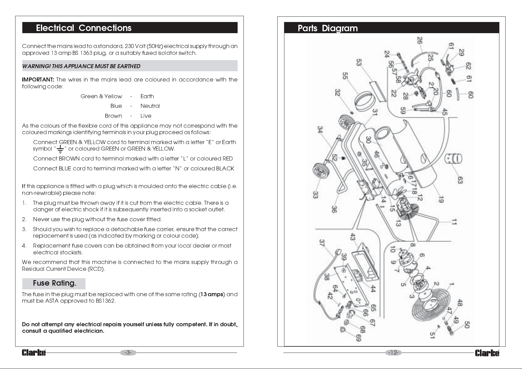
Parts Diagram
IMPORTANT:
following code:
As the colours of the flexible cord of this appliance may not correspond with the
coloured markings identifying terminals in your plug proceed as follows:
Connect GREEN & YELLOW cord to terminal marked with a letter E or Earth
symbol or coloured GREEN or GREEN & YELLOW.
Connect BROWN cord to terminal marked with a letter L or coloured RED
Connect BLUE cord to terminal marked with a letter N or coloured BLACK
If this appliance is fitted with a plug which is moulded onto the electric cable (i.e.
non-rewirable) please note:
1. The plug must be thrown away if it is cut from the electric cable. There is a
danger of electric shock if it is subsequently inserted into a socket outlet.
2. Never use the plug without the fuse cover fitted.
3. Should you wish to replace a detachable fuse carrier, ensure that the correct
replacement is used (as indicated by marking or colour code).
4. Replacement fuse covers can be obtained from your local dealer or most
electrical stockists.
We recommend that this machine is connected to the mains supply through a
Residual Current Device (RCD).
The wires in the mains lead are coloured in accordance with the
Green & Yellow - Earth
Blue - Neutral
Brown - Live
Fuse Rating.
The fuse in the plug must be replaced with one of the same rating (
must be ASTA approved to BS1362.
Do not attempt any electrical repairs yourself unless fully competent. If in doubt,
consult a qualified electrician.
-3-
13 amps
) and
-12-
Page 5
Troubleshooting
FAULT CAUSE REMEDY
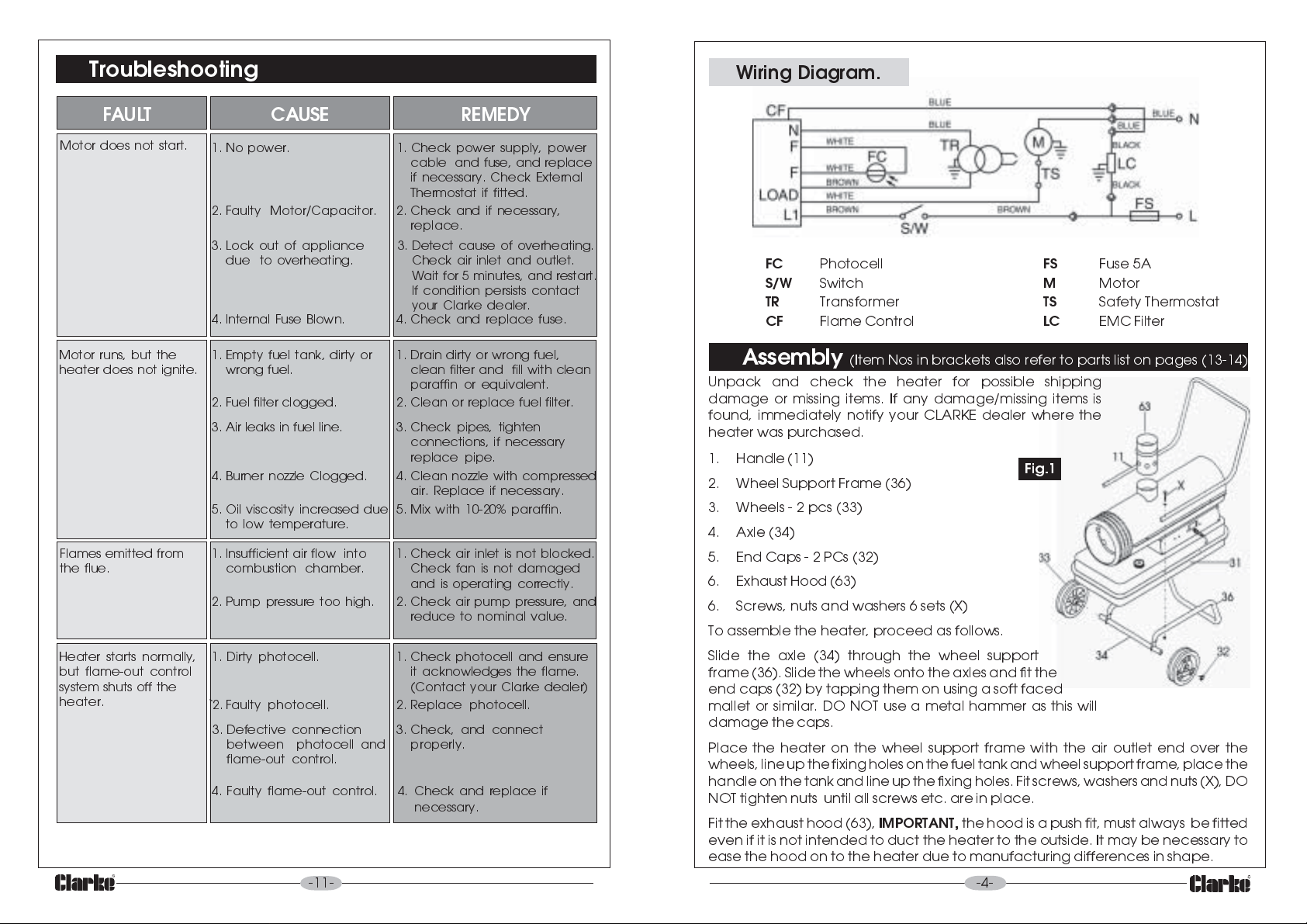
Wiring Diagram.
Motor does not start.
Motor runs, but the
heater does not ignite.
Flames emitted from
the flue.
Heater starts normally,
but flame-out control
system shuts off the
heater.
1. No power. 1. Check power supply, power
2. Faulty Motor/Capacitor. 2. Check and if necessary,
3. Lock out of appliance
due to overheating.
4. Internal Fuse Blown. 4. Check and replace fuse.
1. Empty fuel tank, dirty or
wrong fuel.
2. Fuel filter clogged.
3. Air leaks in fuel line. 3. Check pipes, tighten
4. Burner nozzle Clogged. 4. Clean nozzle with compressed
5. Oil viscosity increased due
to low temperature.
1. Insufficient air flow into
combustion chamber.
2. Pump pressure too high. 2. Check air pump pressure, and
1. Dirty photocell. 1. Check photocell and ensure
`2. Faulty photocell. 2. Replace photocell.
3. Defective connection
between photocell and
flame-out control.
4. Faulty flame-out control. 4. Check and replace if
cable and fuse, and replace
if necessary. Check External
Thermostat if fitted.
replace.
3. Detect cause of overheating.
Check air inlet and outlet.
Wait for 5 minutes, and restart.
If condition persists contact
your Clarke dealer.
1. Drain dirty or wrong fuel,
clean filter and fill with clean
paraffin or equivalent.
2. Clean or replace fuel filter.
connections, if necessary
replace pipe.
air. Replace if necessary.
5. Mix with 10-20% paraffin.
1. Check air inlet is not blocked.
Check fan is not damaged
and is operating correctly.
reduce to nominal value.
it acknowledges the flame.
(Contact your Clarke dealer)
3. Check, and connect
properly.
necessary
.
-11-
FC
S/W
TR
CF
Assembly
Photocell
Switch
Transformer
Flame Control
FS
M
TS
LC
Fuse 5A
Motor
Safety Thermostat
EMC Filter
(Item Nos in brackets also refer to parts list on pages (13-14)
Unpack and check the heater for possible shipping
damage or missing items. If any damage/missing items is
found, immediately notify your CLARKE dealer where the
heater was purchased.
1. Handle (11)
Fig.1
2. Wheel Support Frame (36)
3. Wheels - 2 pcs (33)
4. Axle (34)
5. End Caps - 2 PCs (32)
6. Exhaust Hood (63)
6. Screws, nuts and washers 6 sets (X)
To assemble the heater, proceed as follows.
Slide the axle (34) through the wheel support
frame (36). Slide the wheels onto the axles and fit the
end caps (32) by tapping them on using a soft faced
mallet or similar. DO NOT use a metal hammer as this will
damage the caps.
Place the heater on the wheel support frame with the air outlet end over the
wheels, line up the fixing holes on the fuel tank and wheel support frame, place the
handle on the tank and line up the fixing holes. Fit screws, washers and nuts (X), DO
NOT tighten nuts until all screws etc. are in place.
Fit the exhaust hood (63),
IMPORTANT,
the hood is a push fit, must always be fitted
even if it is not intended to duct the heater to the outside. It may be necessary to
ease the hood on to the heater due to manufacturing differences in shape.
-4-
Page 6
Installation
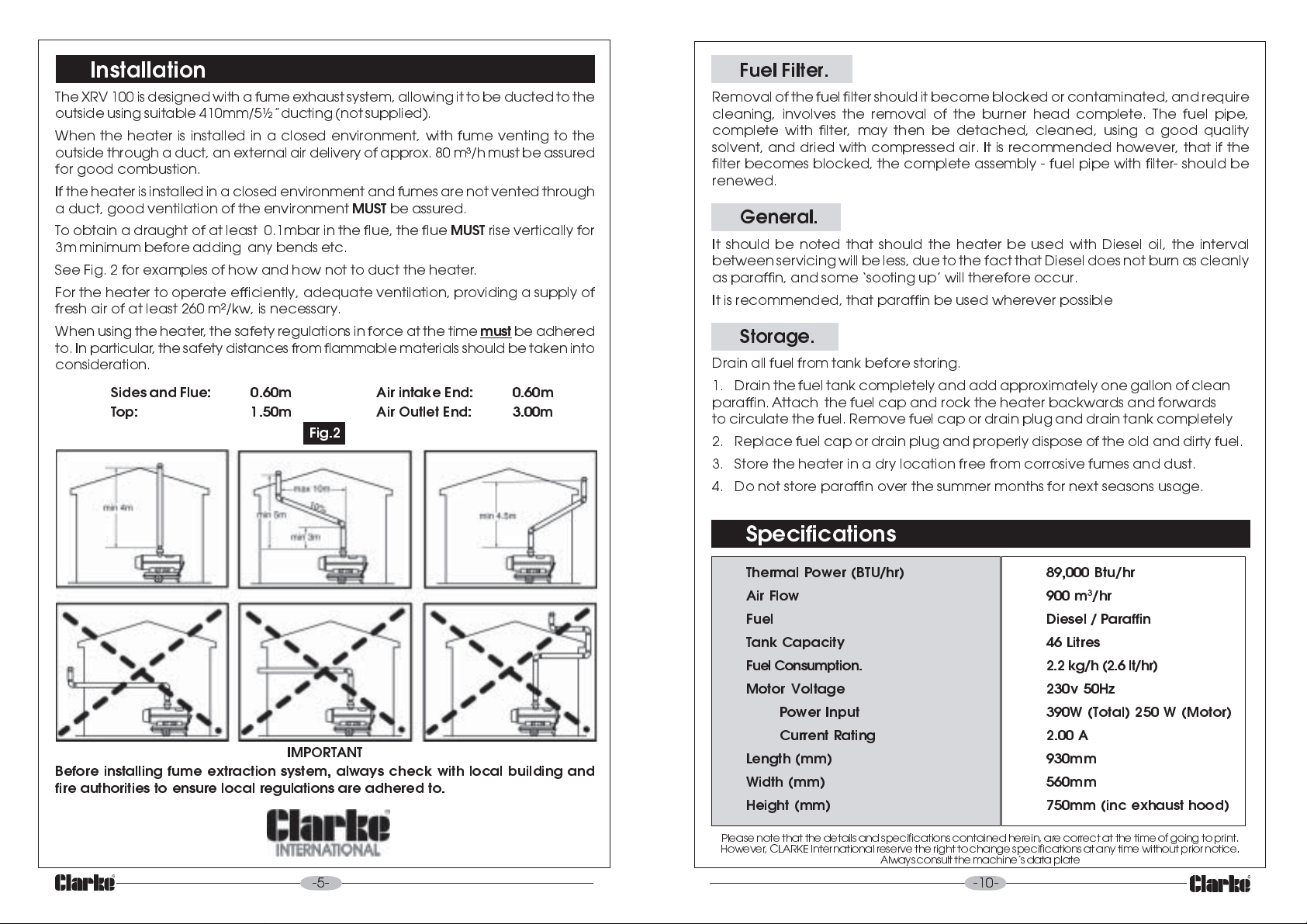
The XRV 100 is designed with a fume exhaust system, allowing it to be ducted to the
outside using suitable 410mm/5½ducting (not supplied).
When the heater is installed in a closed environment, with fume venting to the
outside through a duct, an external air delivery of approx. 80 m³/h must be assured
for good combustion.
If the heater is installed in a closed environment and fumes are not vented through
a duct, good ventilation of the environment
To obtain a draught of at least 0.1mbar in the flue, the flue
3m minimum before adding any bends etc.
See Fig. 2 for examples of how and how not to duct the heater.
For the heater to operate efficiently, adequate ventilation, providing a supply of
fresh air of at least 260 m²/kw, is necessary.
When using the heater, the safety regulations in force at the time
to. In particular, the safety distances from flammable materials should be taken into
consideration.
Sides and Flue: 0.60m Air intake End: 0.60m
Top: 1.50m Air Outlet End: 3.00m
Fig.2
MUST
be assured.
MUST
rise vertically for
must
be adhered
Fuel Filter.
Removal of the fuel filter should it become blocked or contaminated, and require
cleaning, involves the removal of the burner head complete. The fuel pipe,
complete with filter, may then be detached, cleaned, using a good quality
solvent, and dried with compressed air. It is recommended however, that if the
filter becomes blocked, the complete assembly - fuel pipe with filter- should be
renewed.
General.
It should be noted that should the heater be used with Diesel oil, the interval
between servicing will be less, due to the fact that Diesel does not burn as cleanly
as paraffin, and some sooting up will therefore occur.
It is recommended, that paraffin be used wherever possible
Storage.
Drain all fuel from tank before storing.
1. Drain the fuel tank completely and add approximately one gallon of clean
paraffin. Attach the fuel cap and rock the heater backwards and forwards
to circulate the fuel. Remove fuel cap or drain plug and drain tank completely
2. Replace fuel cap or drain plug and properly dispose of the old and dirty fuel.
3. Store the heater in a dry location free from corrosive fumes and dust.
4. Do not store paraffin over the summer months for next seasons usage.
IMPORTANT
Before installing fume extraction system, always check with local building and
fire authorities to ensure local regulations are adhered to.
-5-
Specifications
Thermal Power (BTU/hr) 89,000 Btu/hr
3
Air Flow 900 m
Fuel Diesel / Paraffin
Tank Capacity 46 Litres
Fuel Consumption. 2.2 kg/h (2.6 lt/hr)
Motor Voltage 230v 50Hz
Power Input 390W (Total) 250 W (Motor)
Current Rating 2.00 A
Length (mm) 930mm
Width (mm) 560mm
Height (mm) 750mm (inc exhaust hood)
Please note that the details and specifications contained herein, are correct at the time of going to print.
However , CLARKE International reserve the right to change specifications at any time without prior notice.
Always consult the machines data plate
-10-
/hr
Page 7
Bi-Monthly.
Fan.
Having removed the top cover, thoroughly clean the fan using a cloth moistened
with paraffin or light solvent, and dry using an air line if possible.
Output Air Filter.
Remove the grille, and pull off the Intake Air Filter, revealing the 3 screws securing
the filter housing. Remove the screws and pull off the housing to reveal the Output
Air Filter. If contaminated, this filter must be renewed.
In dirty environments this procedure should be carried out monthly.
Nozzle.
Having removed the top cover, gently unscrew and remove the burner head,
and unscrew the nozzle. Clean, using compressed air and a soft brush, if
necessary. DO NOT prod or poke the nozzle in any way, with a metal tool.
Following a period of Storage.
Operation
Understanding the basic operation of the heater, will reinforce the need to
maintain the unit in top condition at all times, whilst
precautions.
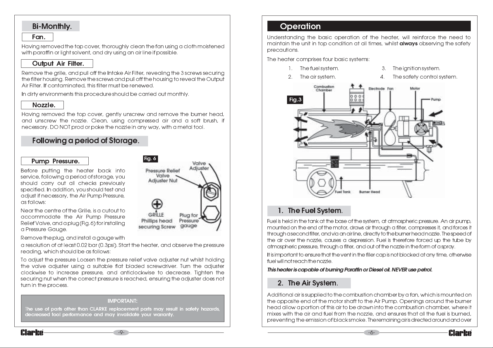
The heater comprises four basic systems:
1. The fuel system. 3. The ignition system.
2. The air system. 4. The safety control system.
Fig.3
always
observing the safety
Pump Pressure.
Before putting the heater back into
service, following a period of storage, you
should carry out all checks previously
specified. In addition, you should test and
adjust if necessary, the Air Pump Pressure,
as follows:
Near the centre of the Grille, is a cutout to
accommodate the Air Pump Pressure
Relief Valve, and a plug (Fig. 6) for installing
a Pressure Gauge.
Remove the plug, and install a gauge with
a resolution of at least 0.02 bar (0.3psi). Start the heater, and observe the pressure
reading, which should be as follows:
To adjust the pressure Loosen the pressure relief valve adjuster nut whilst holding
the valve adjuster using a suitable flat bladed screwdriver. Turn the adjuster
clockwise to increase pressure, and anticlockwise to decrease. Tighten the
securing nut when the correct pressure is reached, ensuring the adjuster does not
turn in the process.
IMPORTANT:
T
he use of parts other than CLARKE replacement parts may result in safety hazards,
decreased tool performance and may invalidate your warranty.
Fig. 6
1. The Fuel System
Fuel is held in the tank at the base of the system, at atmospheric pressure. An air pump,
mounted on the end of the motor, draws air through a filter, compresses it, and forces it
through a second filter, and via an air line, directly to the burner head nozzle. The speed of
the air over the nozzle, causes a depression. Fuel is therefore forced up the tube by
atmospheric pressure, through a filter, and out of the nozzle in the form of a spray.
It is important to ensure that the vent in the filler cap is not blocked at any time, otherwise
fuel will not reach the nozzle.
This heater is capable of burning Paraffin or Diesel oil. NEVER use petrol.
2. The Air System
Additional air is supplied to the combustion chamber by a fan, which is mounted on
the opposite end of the motor shaft to the Air Pump. Openings around the burner
head allow a portion of this air to be drawn into the combustion chamber, where it
mixes with the air and fuel from the nozzle, and ensures that all the fuel is burned,
preventing the emission of black smoke. The remaining air is directed around and over
.
.
-9-
-6-
Page 8
the combustion chamber, until it finally mixes with the heated air from the combustion
chamber, and is ejected as a jet of clean hot air.
Maintenance
(Item Nos in brackets, ref to Parts List on page 12)
3. The Ignition System.
A constant arc is struck between the electrodes, which ignites the air and fuel
mixture. It is important that the electrode gap is correctly maintained, otherwise
arcing will not take place...see Maintenance.
4. The Safety Control System.
A light sensitive photo cell (flame sensor) trips the motor if the flame goes out for
any reason, causing the heater to shut down.
Starting Procedure
Warning!
Before starting the heater, you MUST ensure that the minimum ventilation
requirements are observed, to avoid the risk of carbon monoxide poisoning.
Ensure the fuel tank is filled with clean diesel/paraffin, before plugging in to a
suitably earthed supply.
Observing all precautions previously stated, push The start switch - I located on
the left side of the machine.
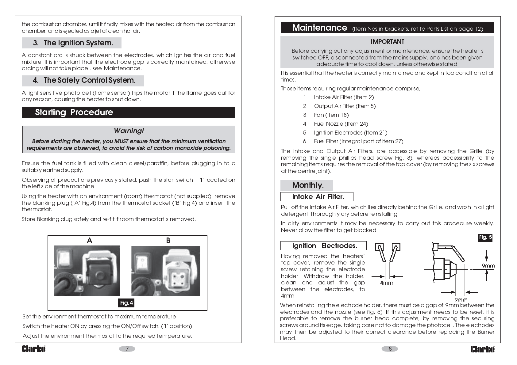
Using the heater with an environment (room) thermostat (not supplied), remove
the blanking plug (A Fig.4) from the thermostat socket (B Fig.4) and insert the
thermostat.
Store Blanking plug safely and re-fit if room thermostat is removed.
AB
Fig.4
Set the environment thermostat to maximum temperature.
Switch the heater ON by pressing the ON/Off switch, (I position).
Adjust the environment thermostat to the required temperature.
-7-
IMPORTANT
Before carrying out any adjustment or maintenance, ensure the heater is
switched OFF, disconnected from the mains supply, and has been given
adequate time to cool down, unless otherwise stated.
It is essential that the heater is correctly maintained and kept in top condition at all
times.
Those items requiring regular maintenance comprise,
1. Intake Air Filter (Item 2)
2. Output Air Filter (Item 5)
3. Fan (Item 18)
4. Fuel Nozzle (Item 24)
5. Ignition Electrodes (Item 21)
6. Fuel Filter (Integral part of item 27)
The Intake and Output Air Filters, are accessible by removing the Grille (by
removing the single phillips head screw Fig. 8), whereas accessibility to the
remaining items requires the removal of the top cover (by removing the six screws
at the centre joint).
Monthly.
Intake Air Filter.
Pull off the Intake Air Filter, which lies directly behind the Grille, and wash in a light
detergent. Thoroughly dry before reinstalling.
In dirty environments it may be necessary to carry out this procedure weekly.
Never allow the filter to get blocked.
Fig. 5
Ignition Electrodes.
Having removed the heaters
top cover, remove the single
screw retaining the electrode
holder. Withdraw the holder,
clean and adjust the gap
between the electrodes, to
4mm.
When reinstalling the electrode holder, there must be a gap of 9mm between the
electrodes and the nozzle (see fig. 5). If this adjustment needs to be reset, it is
preferable to remove the burner head complete, by removing the securing
screws around its edge, taking care not to damage the photocell. The electrodes
may then be adjusted to their correct clearance before replacing the Burner
Head.
-8-
 Loading...