

Page 1
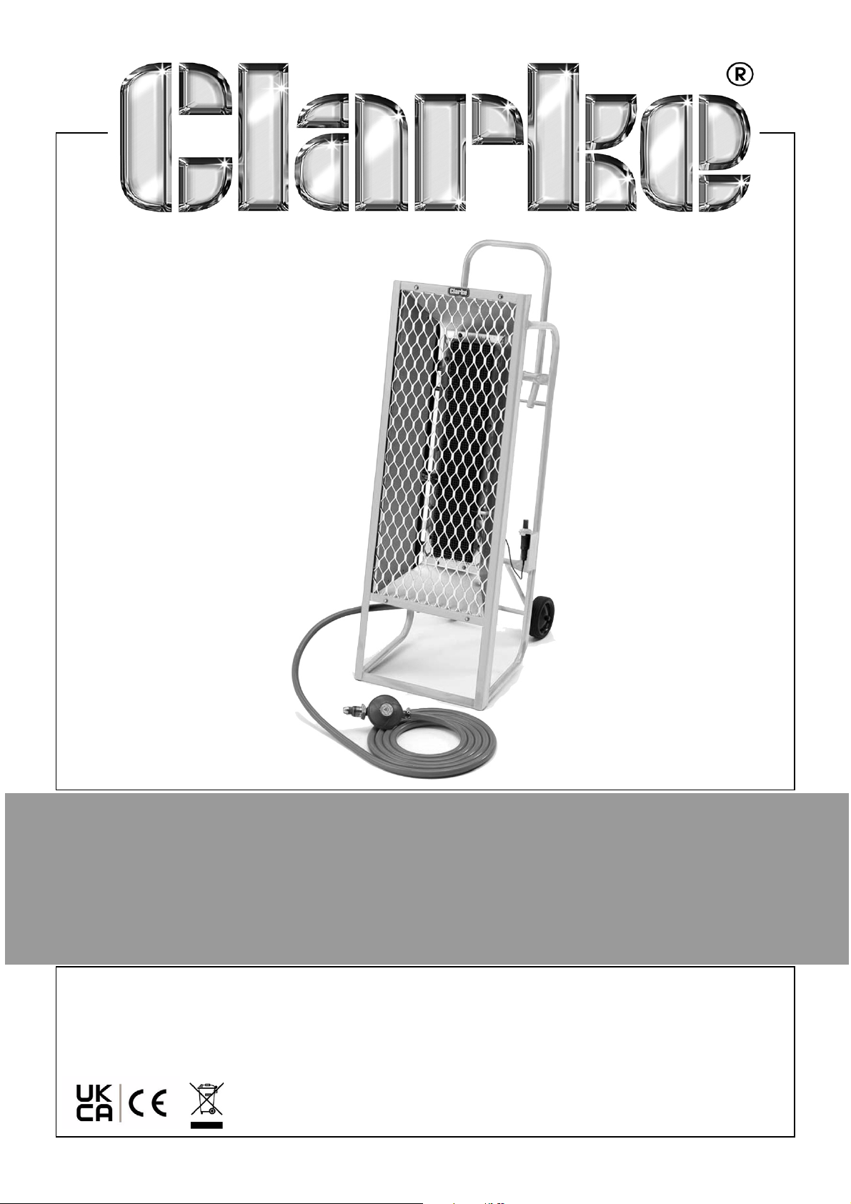
PROPANE GAS HEATER
MODEL NO: GRH35
PART NO: 6920016
OPERATION & MAINTENANCE
INSTRUCTIONS
ORIGINAL INSTRUCTIONS DL0722 - Issue 10
Page 2

INTRODUCTION
Thank you for purchasing this CLARKE Gas Heater. designed for industrial use only, i.e.
NOT for domestic use.
This portable gas heater is designed to BS 4096 for industrial applications, to give safe,
efficient and reliable operation, and is for use with Propane Gas only. Propane gas
bottles are not supplied with the unit, but are readily available from builders merchants
or gas suppliers.
As with all mechanical equipment, optimum performance will only be achieved if the
correct application and servicing procedures are followed.
Before attempting to use this product, please read this manual thoroughly and follow
the instructions carefully. In doing so you will ensure the safety of yourself and that of
others around you, and you can look forward to your purchase giving you long and
satisfactory service.
Proper combustion depends upon the air flow; therefore, the heater must not be
modified or operated with parts removed or missing. Likewise, safety systems must not
be circumvented or modified in order to operate the heater.
FUNCTION AND OPERATING PARAMETERS
This is gas powered heater. It’s intended use is for drying and the warming of
commercial/industrial buildings where adequate ventilation is provided.
• It must be operated as prescribed in the operating manual.
• Is not intended to be used for domestic use or for the heating of habitable areas.
• Is not intended to be used to reach and maintain a certain level of human
thermal comfort within an enclosed space in which the heater is situated.
• Is not intended to be used in enclosed areas with restricted ventilation.
• Is not for use in areas with high levels of fluctuating drafts.
• Is not intended for warming animals or live stock.
2
Parts & Service: 020 8988 7400 / E-mail: [email protected] or [email protected]
Page 3
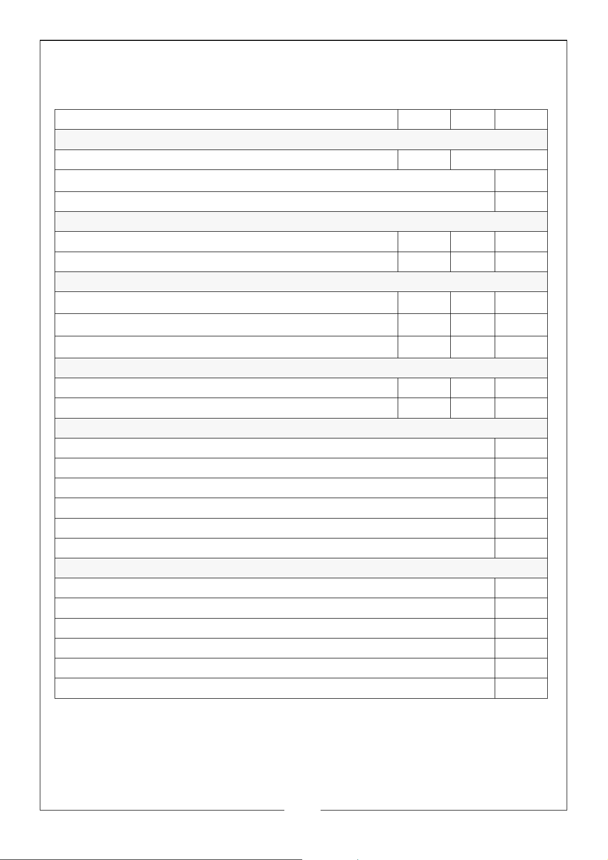
THE FOLLOWING TABLE ADDRESSES THE INFORMATION
REQUIREMENTS OF REG.2015/1188
Item Symbol Value Unit
Fuel
LPG butane Gaseous 28
[mg/kWh
input
] (GCV)
Space Heating Emission(*) No
Indirect heating fuctionality: [yes/no] No
Heat Output
At nominal heat output
At minimum heat output (indicative)
Pnom
Pnom
4.2 kW
1.55 kW
Auxiliary electricity consumption
At nominal heat output el
At minimum heat output el
In standby mode el
max
min
SB
N/A kW
N/A kW
0kW
Useful Efficiency (NCV)
At nominal heat output
At minimum heat output
nth, nom
nth, nom
91 %
N/A %
Type of heat output/room temperature control (select one)
Single stage heat output, no temperature control No
X
Two or more manual stages, no temperature control Yes
With mechanical thermostat temp control No
With electronic temperature control No
Electronic temperature control with day timer No
Electronic temperature control with week timer No
Other control options (multiple selections possible)
Room temperature control with presence detection No
Room temperature control with open window detection No
Room temperature control with distance control option No
Room temperature control with adaptive start control No
Room temperature control with working time limitation No
Room temperature control with black bulb sensor No
3
Parts & Service: 020 8988 7400 / E-mail: [email protected] or [email protected]
Page 4

GENERAL SAFETY PRECAUTIONS
Read, and make sure you fully understand the following precautions and the hazards
associated with this type of equipment.
1. Check the heater thoroughly for damage. DO NOT operate a damaged heater.
2. DO NOT modify the heater or operate a heater which has been modified from its
original condition.
3. Use only propane gas.
4. Use only VAPOUR WITHDRAWAL propane supply. If there is any question about
vapour withdrawal, ask your propane dealer.
5. Mount the propane cylinders vertically (shut-off valve up). Secure them from falling
or being knocked over and protect them from damage.
6. Locate propane containers at least 6ft from the heater and do not direct the
exhaust toward containers.
7. IMPORTANT: Use only the hose and regulator assembly provided with the heater.
Inspect the hose assembly before each use of the heater. If there is excessive
abrasion or wear, or hose is cut, replace with the hose assembly listed on the parts list
before using the heater.
8. Not to be used for the heating of habitable areas of domestic premises; for use in
public buildings, refer to national regulations.
9. For indoor use only in well ventilated areas.
10. If at any time gas odor is detected, IMMEDIATELY STOP operation until the source of
gas has been located and corrected.
11. Install the heater such that it is not directly exposed to water spray, rain and/or
dripping water.
12. Maintain minimum clearance from normal combustible material (e.g. like paper)
stated on page 4.
13. Due to the high surface and exhaust temperatures, adults and children must
observe sufficient clearances to avoid burns or clothing ignition.
14. Operate only on a stable, level surface.
15. Do not use with duct work. Do not restrict air inlet or exit.
16. Do not move, handle or service while hot or burning.
17. Use only in accordance with local codes
18. Do not place torsional stress on any hoses.
4
Parts & Service: 020 8988 7400 / E-mail: [email protected] or [email protected]
Page 5
MINIMUM FRESH AIR OPENING REQUIREMENTS
• Do not use in unventilated areas.
• The flow of combustion and ventilation air must not be obstructed.
Warning: PROVIDE AT LEAST 3FT2 OPENING OF FRESH, OUTSIDE AIR WHILST
RUNNING THIS HEATER. IF PROPER FRESH OUTSIDE AIR VENTILATION IS NOT
PROVIDED, CARBON MONOXIDE POISONING CAN OCCUR.
MINIMUM CLEARANCES FROM COMBUSTIBLES
Front 8 Ft Top 4 Ft
Sides 4 Ft
RISKS OF CARBON MONOXIDE POISONING
Even though this heater operates very close to 100 percent combustion efficiency, it still
produces small amounts of carbon monoxide.
• Carbon Monoxide (CO) is toxic.
• Pregnant women, persons with a heart or lung condition, anaemia or under
the influence of alcohol, or those at high altitude, are more likely to be
effected by Carbon Monoxide.
• CO can build up in a confined space and failure to provide adequate
ventilation can be fatal.
The early symptoms of asphyxiation caused by inadequate ventilation are:
• headache • nausea
• dizziness • dry mouth or sore throat
Should anyone show these symptoms, they must GET FRESH AIR IMMEDIATELY. Turn off the
heater and have it serviced before using again.
Be sure to follow all warnings in this manual.
WE RECOMMEND THE USE OF A CARBON MONOXIDE
DETECTOR
5
Parts & Service: 020 8988 7400 / E-mail: [email protected] or [email protected]
Page 6

IF YOU SMELL GAS
LP gas and natural gas have man-made
odorants added specifically for detection
of fuel gas leaks.
If a gas leak occurs you should be able to
smell the fuel gas. Since Propane (LP) is
heavier than air you should smell for the
gas odour near to the floor. ANY GAS
ODOUR IS YOUR SIGNAL TO GO INTO
IMMEDIATE ACTION!
1. Do not take any action that could
ignite the fuel gas. Do not operate
any electrical switches. Do not pull
any power supply or extension cables.
Do not light matches or any other
source of flame. Do not use your
telephone.
2. Get everyone out of the building and
away from the area immediately.
3. Close all propane (LP) gas tank or
cylinder fuel supply valves, or the main
fuel supply valve located at the meter
if you use natural gas.
4. Propane (LP) gas is heavier than air
and may settle in low areas. When you
have reason to suspect a propane
leak, keep out of all low areas.
5. Use your neighbours phone and call
your fuel gas supplier and your fire
department. Do not re-enter the
building or area.
6. Stay out of the building and away
from the area until declared safe by
the firefighters and your fuel gas
supplier.
7. FINALLY. let the fuel gas service person
and the firefighters check for escaped
gas. Have them ventilate the building
and area before you return. Properly
trained service people must repair any
leaks, check for further leakages. and
then re light the appliance for you.
8. If you smell even a small amount of
gas, CONTACT YOUR FUEL GAS
SUPPLIER IMMEDIATELY. DO NOT WAIT!
NO ODOUR DETECTED
1. Some people cannot smell the odour
added to propane (LP) or natural gas.
You must determine if you can smell
the odourant in these fuel gases.
2. Learn to recognize the odour of
propane (LP) gas and natural gas.
Local propane (LP) gas dealers will be
more than happy to give you a
scratch and sniff pamphlet. Use it to
become familiar with the fuel gas
odour.
3. Smoking can decrease your ability to
smell. Being around an odour for a
period of time can affect your
sensitivity to that particular odour.
odours present in animal confinement
buildings can mask fuel gas odour.
ODOUR FADING
1. The odourant in propane (LP) gas and
natural gas is colorless and the
intensity of its odour can fade under
some circumstances.
2. If there is an underground leak, the
movement of gas through the soil can
filter the odourant.
3. Propane (LP) gas odour may differ in
intensity at different levels. Since
Propane (LP) gas is heavier than air,
there may be more odour at lower
levels.
4. Always be sensitive to the slightest gas
odour. If you continue to detect any
gas odour, no matter how small, treat
it as a serious leak.
CRITICAL POINTS TO REMEMBER!
1. Propane (LP) gas has a distinctive
odour. Learn to recognize the odours.
2. A periodic sniff test around the joints;
i.e. hose, connections. etc., is a good
safety practice under any conditions.
6
Parts & Service: 020 8988 7400 / E-mail: [email protected] or [email protected]
Page 7

FEATURES OF THE GRH35
Understanding the basic operation of the heater will reinforce the need to maintain the
unit in top condition at all times whilst always observing the safety precautions.
The heater comprises three basic systems:
1. The gas system. 2. The ignition system. 3. The safety control system.
GAS SYSTEM
The gas supply to the machine is by means of a high pressure hose, connected to a LPG
cylinder, via a pressure regulator.
When the gas valve is opened, gas will flow to the Control Valve and finally the burner.
This heaters is designed for use with PROPANE gas ONLY. Gas bottles are not supplied,
but are readily available from builders merchants or gas suppliers etc.
This heater is designed to operate with a minimum 20 pound (9 kg) propane tank. You
may need two or more tanks or one larger tank in colder weather. Use a 100 pound (45
kg) tank for longer operation or in very cold weather. Less gas is vaporized at lower
temperatures. Your local propane gas dealer will help you select the proper supply
o
system. The minimum surrounding air temperature rating for each heater is -20
o
C).
29
F (-
IGNITION SYSTEM
A Piezo-electric igniter is positioned at the burner head. When the Igniter button is
depressed, a high intensity spark is generated, which ignites the gas. Heat from the
flame is sensed by a thermocouple, which is connected to the Flame Failure Valve. As
the thermocouple heats up the cut-off valve opens, so that after a short period, the
Control Valve button (see Operation) may be released and the main flame is
established.
THE SAFETY CONTROL SYSTEM
Should the flame extinguish for any reason, the Thermocouple will quickly cool, causing
the Flame Failure Valve to close, shutting off the gas supply.
Additionally, the machine is fitted with a ‘Tip Over Switch’, which operates should the
heater be moved from the vertical position i.e. tip over, thereby shutting off the gas.
ALWAYS ensure that the Tip-Over switch is perfectly vertical and secure.
INSTALLATION
Read these instructions carefully. Do not allow anyone who has not read these
instructions to light, adjust, or operate this heater.
Do not attempt to operate the heater with any gas other than propane.
This heater, including hose and regulator assembly, must be inspected at least annually
by a qualified service person. If the hose shows evidence of excessive abrasion or wear
7
Parts & Service: 020 8988 7400 / E-mail: [email protected] or [email protected]
Page 8

or if the hose is cut, it must be replaced prior to the heater being put into operation. The
replacement hose assembly shall be that specified by the Clarke International.
UNPACKING
1. Remove heater from carton.
2. Remove all protective material which may have been applied to the heater for
shipment.
3. Check the heater for possible shipping damage. Should any damage be apparent,
please notify your Clarke dealer immediately.
LOCATING THE HEATER
Although this heater incorporates a ‘tip-over’ switch, the heater and propane gas
cylinder must be located on a hard, flat, level surface to minimize the risk of accidental
tipping. The propane gas cylinder should be adequately restrained to prevent
accidental tipping. Only operate this heater with the supply cylinder in the upright
position.
This appliance must be installed only in locations where the potential for physical
damage to the appliance, or to individuals (burns), is reduced to a minimum.
The heater must be installed in a location such that it will not be exposed directly to
water spray, rain and/or dripping water.
Use of this heater in a draft/windy area decreases its efficiency. If possible, operate the
unit in a draft free area.
The heater must be located at least 6 feet away from the propane cylinder and must
not be directed towards any gas cylinder.
If more than one heater is to be used, they and the supply cylinders must be separated
by at least 20 feet.
Position the heater at a safe distance from combustible materials.
This heater must not be placed on wooden floors or other combustible materials.
When used, the heater should rest on suitable insulating material at least 1 inch thick
and extending 3 ft. or more beyond the heater in all directions.
GAS CONNECTION
The hose for connecting the heater to the gas bottles is supplied loose and must be
fitted by the user. Ensure the connection is tight. Do not use PTFE tape.
The connection to a propane cylinder must be made in a well ventilated area using the
regulator and hose assembly supplied with the appliance. DO NOT attempt to adjust
this regulator. It has been preset at the factory to provide safe and proper operation of
the appliance.
Attach the regulator to the gas cylinder ensuring the cylinder orifice is perfectly clean blow out with compressed air if necessary, or open the gas valve quickly and briefly to
blast away any dust or dirt. Turn the nut in an anticlockwise direction - i.e. LEFT HAND
THREAD, until tight. DO NOT use a thread compound on threads. To check for leaks, use
soapy water, or liquid soap ONLY.
8
Parts & Service: 020 8988 7400 / E-mail: [email protected] or [email protected]
Page 9
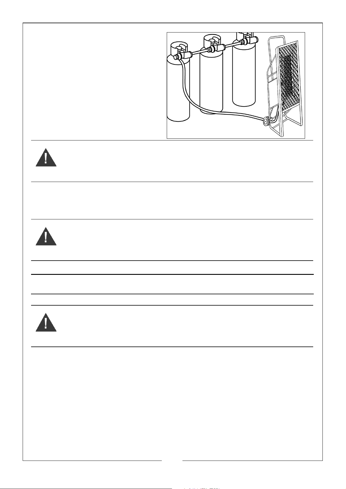
IMPORTANT: The gas hose and cylinder
must ALWAYS be located behind the
machine - at a distance of at least 6
feet.
In order to reduce the risk of icing up,
when operating at long periods of
maximum capacity, you should use a
larger capacity gas bottle or two/three
bottles in parallel, as shown.
The tee piece and ‘pigtails’ are readily
available from builders merchants or gas
suppliers
.
WARNING: Propane Gas cylinders must be used and stored in
accordance with the ‘HIGHLY FLAMMABLE LIQUIDS AND LIQUEFIED
PETROLEUM GASES REGULATIONS 1972.
Open the cylinder's gas valve and check all gas connections with a soap and water
solution. DO NOT USE A FLAME.
lways use full cylinders with good air circulation and no frost on the cylinders.
A
WARNING: If you do not follow these instructions exactly, a fire or
explosion may result causing property damage, personal injury or loss
of life.
OPERATING INSTRUCTIONS
WARNING: BEFORE STARTING THE HEATER, YOU MUST ENSURE THAT THE
MINIMUM VENTILATION REQUIREMENTS ARE OBSERVED TO AVOID THE
RISK OF CARBON MONOXIDE POISONING.
FIRST USE
The heater reaches a very high temperature and during first use you may notice an
odour coming from the heater - this is quite normal and will disperse quickly (It is
recommended the heater is initially run outside to enable the odour to clear).
It should also be noted that the paint on the surface of the heater will discolour due to
the heat being produced.
LIGHTING THE HEATER
1. Ensuring there is sufficient gas, and that it is correctly connected and leak free, turn
on the gas supply and check all fittings and connections for gas leaks using a mild
9
Parts & Service: 020 8988 7400 / E-mail: [email protected] or [email protected]
Page 10
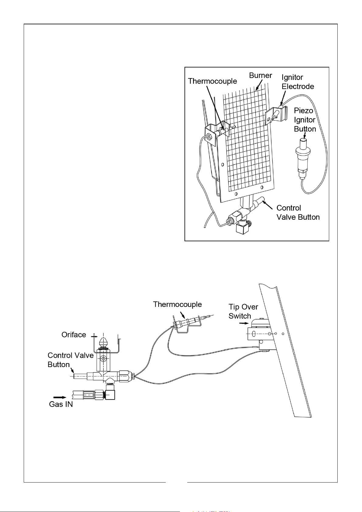
soap and water solution. NEVER use a match to check for gas leaks. When satisfied,
open the valve on the gas cylinder.
NOTE: The heater, has a fixed, regulated gas flow.
2. Press and hold the control valve
plunge as shown whilst continually
pressing the piezo-electric button until
the burner ignites.
• Once the burner ignites, keep the
button pressed for one (1) minute
or until the burner stays lit after it is
released.
WARNING: DO NOT FACE THE HEATER
ELEMENT WHEN STARTING - ALWAYS
STAND TO ONE SIDE.
NOTE:
3. Alternatively, hold a lit taper to the
If a new gas cylinder has been
connected, it may take some
time for the gas line to be purged
of air. Press the Piezo electric
button every10-15 seconds until it
ignites.
burner face while pressing and
holding the control valve button. After the burner ignites, keep button pressed for
one (1) minute or until the burner stays lit after releasing button.
WARNING: WHEN LIGHTING THE BURNER WITH A TAPER, LIGHT AT THE BOTTOM OF
THE SCREEN, NOT AT THE ORIFICE.
NOTE:
In cases where long runs of gas supply lines have been installed ahead of the
appliance, it may be necessary to bleed trapped air out of supply lines before
10
Parts & Service: 020 8988 7400 / E-mail: [email protected] or [email protected]
Page 11
lighting pilot. New installations generally require bleed of supply lines. Wait a
minimum of five minutes after bleeding supply lines before attempting to light
heater.
CAUTION: THIS APPLIANCE IS HOT DURING NORMAL OPERATION. AVOID
PHYSICAL CONTACT. DO NOT PLACE CLOTHING OR OTHER
COMBUSTIBLE MATERIALS ON THIS APPLIANCE.
SHUTTING OFF THE HEATER
1. Close propane gas supply cylinder valve.
2. Observe the burner until flame is extinguished.
3. Listen for closure of the safety valve.
4. DO NOT re-open the propane gas supply cylinder valve before the safety valve
closes.
CLEANING & MAINTENANCE
WARNING: NEVER ATTEMPT TO SERVICE THE HEATER WHILE IT IS
CONNECTED TO THE PROPANE SUPPLY, IS OPERATING, OR IS HOT.
(SEVERE BURNS CAN OCCUR).
1. Turn heater off and let it cool for at least 20 minutes before cleaning.
2. Keep the heater clean. Clean the heater annually or as needed to remove dust and
debris. If the heater is dirty or dusty, clean with a damp cloth. Use household
cleaners on difficult spots. To clean the reflector, remove the screen by undoing the
four securing screws at the front of the unit.
3. Inspect the heater before each use. Check the connections for leaks. Apply a
mixture of liquid soap and water to the connections. Bubbles forming show a leak.
Correct all leaks at once.
4. Clean the inside of the heater using compressed air where possible. Blow air back
and forth along the entire burner face until all dust has been dislodged from the
surface of the screen. Blow air through the venturi from the control (orifice) end of
the heater.
5. Inspect the hose/regulator assembly before each use. If the hose is highly worn or
cut it must be replaced.
6. The heater should be inspected before each use and at least annually by a
qualified person.
11
Parts & Service: 020 8988 7400 / E-mail: [email protected] or [email protected]
Page 12

TROUBLESHOOTING
Fault Cause Remedy
Burner fails to light 1. Gas supply valve
closed.
2. Excess-flow check
valve.
3. Excess-flow check
valve.
4. Piezo ignition not
sparking.
No gas flow to the
burner.
1. Cylinder gas tap closed.
2. Cylinder is empty.
3. Orifice is obstructed.
4. Gas leaks from the
supply hose or from
the tap.
5. Low gas pressure.
6. Thermocouple loose
or needs to be
replaced
7. Automatic control
valve needs to be
replaced.
8. Loose wires on tip over
switch.
9. Loose or broken wire.
10.Loose/mis-located
thermocouple.
11.Defective thermo
-couple.
12.Defective control.
1. Open gas supply valve slowly
2. Close propane supply valve
closed propane tank and re open slowly.
3. Replace burner orifice.
4. Check igniter electrode gap is
5.0 mm (0.195 in). Check wire
lead for damage Replace
piezo igniter and/or igniter
electrode as necessary. Do
not bend electrode, this may
cause breakage.
1. Open the gas tap
2. Replace cylinder.
3. Remove the orifice and clean
it.
4. Use soapy water to find the
leak and repair.
5. Check for proper gas supply.
6. Tighten connection or
replace thermocouple.
7. Replace automatic control
valve.
8. Tighten wires on power switch.
9. Tighten or repair wire.
10.Tighten thermocouple. Make
sure that thermocouple is
located correctly between
reverberator and grid thermo
couple wire.
11.Replace thermocouple.
12.Replace controller.
12
Parts & Service: 020 8988 7400 / E-mail: [email protected] or [email protected]
Page 13
Fault Cause Remedy
Heater stops during operation.
1. Excessive gas supply.
2. Insufficient gas supply
due to ice formation
on the cylinder.
3. The tip-over switch has
tripped.
1. Check the pressure regulator
and replace if necessary.
2. Check & use larger cylinder,
or two or more in parallel.
3. Investigate the cause, heater
has fallen over. Right it and
investigate the cause. Take
steps to prevent
re-occurrence.
SPECIFICATIONS
Model GRH35
Gas Type Propane
Output 10.25 kW (35,000 BTU/Hr)
Regulator Pressure 37 mbar
Regulator flow rate 1.5kg/hr
Fuel Consumption 0.7 kg/hr
Gas Hose Length 2000 mm
Weight unpacked 9.2 kg
Dimensions (L x W x H) 308 x 230 x 850 mm
GUARANTEE
This product is guaranteed against faulty manufacture for a period of 12 months from
the date of purchase. Please keep your receipt which will be required as proof of
purchase.
This guarantee is invalid if the product is found to have been abused or tampered with
in any way, or not used for the purpose for which it was intended.
Faulty goods should be returned to their place of purchase, no product can be
returned to us without prior permission.
This guarantee does not effect your statutory rights.
13
Parts & Service: 020 8988 7400 / E-mail: [email protected] or [email protected]
Page 14
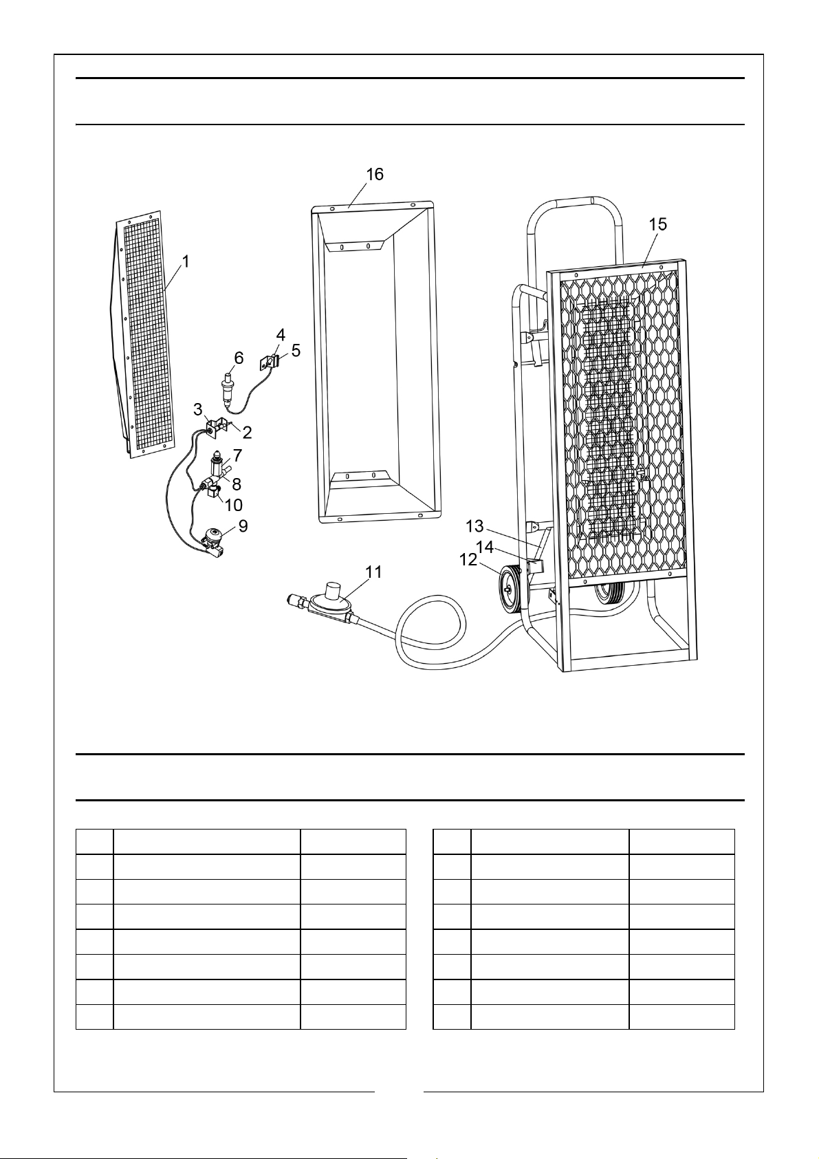
PARTS DIAGRAM
PARTS LIST
1 Burner 115286-01 9 Tip Switch 115285-01
2 Thermocouple 114121-01 10 Brass Elbow 111090-02
3 Bracket 117384-01 11 Hose/Regulator 115290-04
4 Igniter Electrode 115291-01 12 Wheel 115292-01
5 Igniter Bracket 117385-01 13 Wheel Bracket 114156-02
6 Piezo-Igniter Kit 102445-01 14 Wheel Lock 115294-01
7 Orifice 115287-01 15 Main Frame Assy 117297-01
8 Valve 115285-01 16 Reflector 117310-01
14
Parts & Service: 020 8988 7400 / E-mail: [email protected] or [email protected]
Page 15
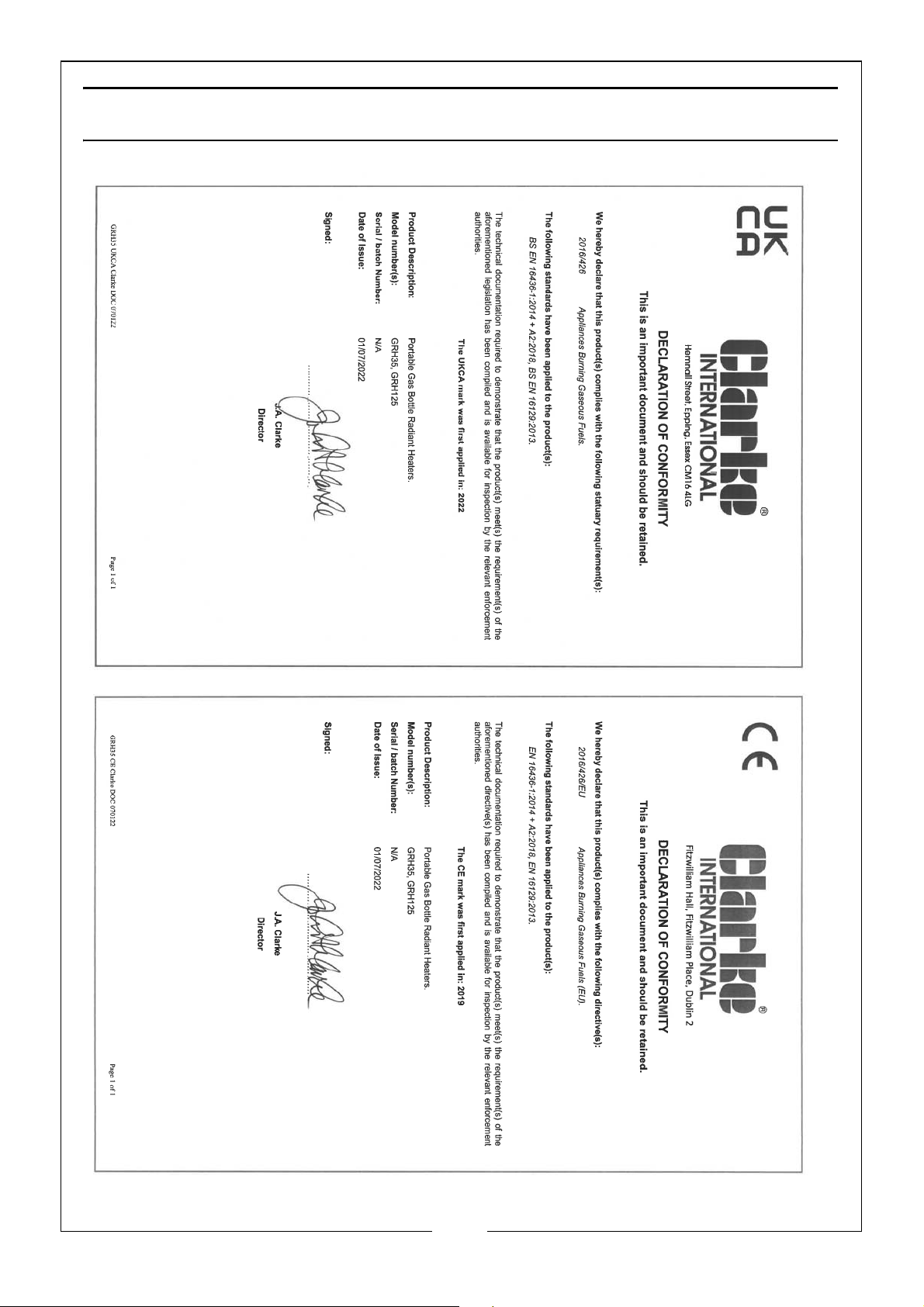
DECLARATION OF CONFORMITY
15
Parts & Service: 020 8988 7400 / E-mail: [email protected] or [email protected]
Page 16

 Loading...