

Page 1
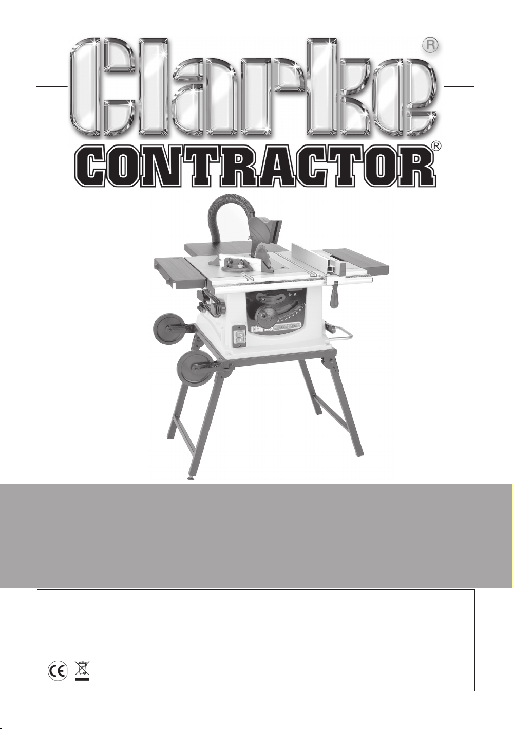
10” TABLE SAW
10” TABLE SAW
Model CTS12
Model CTS12
Part Number 6500750
Operating & Maintenance
Instructions
©
1010
Page 2
SPECIFICATIONS
Model No ..............................................CTS12
Part No. .................................................. 6500754
Motor ..................................................... 230V~ 50Hz 1ph
Power rating ..............................1.5Kw
Speed ........................................ 6270 rpm
Fuse rating ................................. 13Amps
Saw Blade ............................................. 10” dia. (254x30mm) TCT
Maximum depth of cut at 0O..............75 mm
Maximum depth of cut at 45O............50 mm
Net Weight (Boxed)..............................29 kg
Noise level at operating position ........112.3dB LWA (under load)
Overall dimensions - (LxWxH) ..............870 x 920 x 1250 mm
Overall dimensions - with extensions ..870 x 1240 x 1250 mm
Use of machine
This machine is designed to rip and cross cut wood exclusively, up to a maximum thickness of
75mm.
For correct operation it must be fixed and operated as laid down in this manual.
Restrictions of use
This saw is NOT suitable for cutting:
• Timber greater than 75mm in thickness.
• Metal, Stone, Rubber, Plastic, Bones, Etc.
• Logs or round timber.
DO NOT use to rebate, tenon, mould or groove.
DO NOT fit any other tool or combination of blades.
DO NOT use as a free standing machine or as a hand held machine.
DO NOT modify the machine or its guards/controls in any way.
DO NOT use with any covers/guards removed.
When disposing of this product, do not dispose of with general waste. It must be disposed
of according to law at a recognised disposal facility.
2
Page 3
Thank you for purchasing your new CLARKE 10” TABLE SAW.
Before attempting to operate this machine, please read this instruction manual thoroughly and
follow all directions carefully. In doing so you will ensure the safety of both yourself and others
around you, and, at the same time, you should look forward to it providing long and trouble
free service.
GUARANTEE
This product is guaranteed against faults in manufacture for 12 months from purchase date.
Keep your receipt as proof of purchase. This guarantee is invalid if the product has been found
to have been abused in any way, or not used for the purpose for which it was intended, or to
have been tampered with in any way. The reason for return must be clearly stated. This guarantee
does not affect your statutory rights.
CONTENTS
Specifications ............................................................................................. 2
Safety Instructions ...................................................................................... 4
Additional Safety Rules for Table Saws .................................................... 7
Electrical Connections ............................................................................... 8
Features .......................................................................................................9
Glossary of Terms...................................................................................... 10
Unpacking and Checking Contents ......................................................11
Assembly ................................................................................................... 12
Opening the stand ................................................................................... 15
Important Checks before Starting ..........................................................16
Operation ..................................................................................................16
Starting & Stopping .................................................................... 16
Turning the Laser on/off .............................................................16
Adjustment ................................................................................. 17
Cutting Practices ......................................................................................20
Maintenance ............................................................................................ 24
Changing the Saw Blade .......................................................... 24
Adjusting the Positive Stops ...................................................... 25
Motor Brush Renewal .................................................................25
Trouble Shooting .......................................................................................26
Parts Lists and Diagrams .................................................................... 27-30
Declaration of Conformity .......................................................................31
3
Page 4
SAFETY INSTRUCTIONS
KEEP WORK AREA CLEAN : Cluttered areas and benches invite injuries.
CONSIDER WORK AREA ENVIRONMENT: Do not expose power tools to rain. Do not use power tools in damp,
or wet locations. Keep the work area well lit. Do not use this saw in the presence of flammable liquids or
gases.
GUARD AGAINST ELECTRIC SHOCK: Avoid body contact with earthed, or grounded surfaces, e.g. pipes,
radiators, ranges, refrigerators etc.
KEEP CHILDREN AWAY: Do not let children, or persons not involved in the work, touch the tool, or the extension
lead and keep them away from the work area.
STORE IDLE TOOLS: When not in use, all tools should be stored in a dry, locked up place, out of reach of
children.
DO NOT FORCE THE TOOL: It will do the job better and safer at the rate for which it was intended.
USE THE RIGHT TOOL: Do not force small tools, to do the job of a heavy duty tool. Do not use tools for
purposes not intended.
DRESS PROPERLY: Do not wear loose clothing, or jewellery that can be caught in moving parts. Non-skid
footwear is recommended when working outdoors. Wear protective hair covering to contain long hair.
SAFETY GLASSES: Use safety glasses when operating this tool.
DUST MASKS: If the work is dusty, use dust masks to reduce the risk of inhalation of harmful dust.
CONNECT DUST EXTRACTION EQUIPMENT: Always connect a suitable vacuum cleaner attachment.
PROTECT YOUR EARS: Hearing protection should be worn when using this tool.
DO NOT ABUSE THE MAINS LEAD: Never pull the mains lead to disconnect it from the mains socket. Keep
the mains lead away from heat, oil and sharp edges.
SECURE THE WORK: Use clamps, or vices to hold the workpiece. It is safer than using your hand.
DO NOT OVERREACH: Keep proper footing and balance at all times.
MAINTAIN TOOLS WITH CARE: Keep the blade clean for better and safer performance. Follow the instructions
for changing the blade. Inspect the mains lead periodically and if damaged have it repaired by an
authorised service facility. Inspect extension leads periodically and replace if damaged. Keep all handles
and grips dry, clean and free from oil and grease.
DISCONNECT TOOLS: Disconnect tools from the mains supply when not in use, before servicing and when
changing accessories such as blades.
REMOVE ADJUSTING KEYS AND WRENCHES: Form the habit of checking to see that all keys and spanners
are removed from the tool before turning it on.
TRANSPORTING THE TABLE SAW: When moving or transporting the table saw, only lift from the table top. Do
not use the blade guard for lifting, moving or transporting the saw.
AVOID UNINTENTIONAL STARTING: Ensure that the switch is in the off position when plugging in to the mains
supply. (Switch cover locked position).
4
Page 5
SAFETY INSTRUCTIONS
USE OUTDOOR EXTENSION LEADS: When the tool is used outdoors, use only extension leads intended for
outdoor use and so marked. Always make sure that the extension lead is suitably rated for the tool. Position
the extension lead so that it does not create a hazard.
STAY ALERT: Watch what you are doing. Use common sense. Do not operate tools when you are tired.
CHECK DAMAGED PARTS: Before further use of the tool, any part that is damaged should be carefully
checked to determine that it will operate properly and perform its intended function. Check for alignment
of moving parts, free running of moving parts, breakage of parts, mounting and any other conditions that
may affect its operation. Any part that is damaged should be properly repaired, or replaced, by authorised
service personnel, unless otherwise indicated in this User Guide. Have defective switches replaced by
authorised service personnel. Do not use the tool if the switch does not turn it on and off.
WARNING: The use of any accessory, or attachment, other than those recommended in this User Guide,
may present a risk of personal injury.
HAVE YOUR TOOL REPAIRED BY A QUALIFIED PERSON: This electric tool is in accordance with the relevant
safety requirements. Repairs should only be carried out by qualified persons using original spare parts,
otherwise this may result in considerable danger to the user.
SAW BLADES: Do not use saw blades which are damaged or deformed. Use only saw blades recommended
by the manufacturer which conform to EN847-1. Take care that the selection of the saw blade is suitable
for the type of wood to be cut which meets the requirements on page 2. Do not use High Speed Steel
(HSS) blades. Use only saw blades for which the maximum possible speed is not less than the maximum
spindle speed (no load speed) of the table saw and the material to be cut.
USE THE BLADE GUARD: Make sure that the blade guard moves freely on its pivot point and that the front of
the guard is always in contact with the saw table when not cutting. Always use the blade guard and riving
knife for every operation. IMPORTANT: THIS SAW IS NOT DESIGNED FOR NON-THROUGH CUTTING OPERATIONS
SUITABLE MATERIALS : Do not use the saw to cut materials other than wood.
MAXIMUM DEPTH OF CUT: The maximum depth of cut of this table saw is 75 mm. See the Product Specification
on page 2.
PROVIDE ADEQUATE SUPPORT FOR LONG WORKPIECES: Provide adequate support to the rear and sides of
the saw table for wide, or long pieces of work. Saw horses or similar devices should be used to prevent the
ends of the workpiece from drooping.
COMPOUND CUTTING: Take care when making compound cuts. If both mitre angles and bevel angles are
to be set for compound mitre cuts, set the bevel angle first. Make sure that the table saw is disconnected
from the mains supply before changing to the required angles.
ASSEMBLY: Do not operate this saw until it has been fully assembled and correctly prepared for use in
accordance with the instructions in this User Guide.
MIND YOUR HANDS: Keep your hands well away from the blade area at all times. Do not place them in the
path of the blade when operating the saw.
WEAR GLOVES: Wear gloves when handling saw blades and rough material. Saw blades should be carried
in a holder whenever practical.
SECURE HANDLES AND CLAMPS: Make sure that all handles, clamps and guards are securely fitted before
operating the saw. Do not perform any cutting operation freehand.
5
Page 6
SAFETY INSTRUCTIONS
USE THE MITRE GAUGE: Always hold the work firmly against the mitre gauge fence when cross cutting.
LOCK THE GUIDES: Always ensure the rip fence is securely fastened when in use.
USE A PUSH STICK: Use a pushstick to feed the workpiece past the saw blade. The push stick should always
be stored with the machine when not in use.
DO NOT WORK FREEHAND: Never perform any operation ‘freehand’ i.e. do not use your hands alone to
support, or guide the workpiece. Always use either the rip fence, or the mitre gauge (as appropriate) to
position and guide the work.
STAY CLEAR: Never stand, or have any part of your body in line with the path of the saw blade. A small cutoff piece could be caught by the back of the blade and thrown towards the operator. Stand to one side
of the blade. Keep your hands out of the line of the saw blade.
CROSSCUTTING: Move the rip fence out of the way when cross cutting. Never use the rip fence as a cutoff gauge when crosscutting.
SWITCH OFF: If off-cuts of wood become jammed in the machine, switch off and disconnect from the
mains supply before removal.
STALLED BLADE: If the blade stalls, or stops while cutting,
supply before attempting to free the blade.
RIPPING: When ripping or bevel ripping, always use the rip fence together with the push stick. Never make
these cuts freehand. The blade could bind in the cut and cause a
MOUNTING THE SAW TABLE: Mount the table saw to the table before performing any cutting operations.
Refer to the assembly instructions on page 12.
REMOVE THE MITRE GAUGE: Remove the mitre gauge from the table during any cutting operations which
involve the rip fence .
MAXIMUM BLADE EXTENSION: Have the blade extended to approximately 22mm above the top of the
workpiece. Additional blade exposure could be potentially dangerous.
DO NOT REACH OVER: Do not reach over, or behind the blade for any reason.
SMALL PIECES AND TRAPPED PIECES: Do not pick up small pieces of cut-off material from the table. Remove
them by pushing them off the table with the push stick. They could be thrown back at you by the rear of
the blade. Do not remove small pieces of cut-off material that may become trapped inside the blade
guard while the saw is running. This could endanger your hands, or cause a
and when the blade has stopped turning, lift the guard and remove the piece of debris.
REBATING, SLOTTING AND GROOVING: Rebating, slotting and grooving should not be undertaken on the
saw..it is not designed for non-through cutting operations.
turn the switch off
kickback
and disconnect from the mains
.
kickback
. Turn the saw OFF
6
Page 7
ADDITIONAL SAFETY RULES FOR TABLE SAWS
✔ ALWAYS use saw Blade Guard and Riving Knife for every operation.
✔ ALWAYS hold the work firmly against the mitre gauge or fence.
✔ ALWAYS use a push-stick when required. Always use a push-stick for ripping narrow stock.
Refer to ripping applications in instruction manual where push-stick is covered in detail.
✔ ALWAYS use in a well ventilated area. Remove sawdust frequently. Clean out sawdust from
the interior of the saw to prevent a potential fire hazard.
✔ ALWAYS move the rip fence out of the way when crosscutting.
✔ ALWAYS switch off and disconnect from supply before removing off cuts of wood from the
machine
✔ ALWAYS provide adequate support to the rear and sides of the saw table for wide or long
workpieces.
✔ ALWAYS keep the blade sharp, the Rip Fence parallel to the saw blade, and the Riving Knife
and Blade Guard in place. Do not release work before it is pushed all the way past the saw
blade.
✔ ALWAYS avoid awkward operations and hand positions where a sudden slip could cause
your hand to move into the blade.
✘ NEVER stand or have any part of your body in line with the path of the saw blade. Keep
your hands out of the line of the saw blade.
✘ NEVER reach behind or over the blade for any reason.
✘ NEVER use the fence as a cutoff gauge when crosscutting.
✘ NEVER attempt to free a stalled saw blade without first turning the saw OFF. Turn off power
switch immediately to prevent motor damage.
✘ NEVER use solvents to clean plastic parts. Solvents could possibly dissolve or otherwise
damage the material. Only a soft damp cloth should be used to clean plastic parts.
✘ NEVER force feed the work into the blade. A light pressure ONLY is required
✘ NEVER cut metals or materials which may make hazardous dust.
✘ NEVER perform any operation ‘freehand’ which means using your hands to support or guide
the work piece. Always use either the fence or the mitre gauge to position and guide the
work.
7
Page 8
ELECTRICAL CONNECTIONS
WARNING! THIS APPLIANCE MUST BE EARTHED.
Connect the mains lead to a 230 volt (50Hz) domestic electrical supply via a standard 13 amp
BS 1363 plug fitted with a 13 amp fuse, or a suitably fused isolator switch.
IMPORTANT: The wires in the mains lead are coloured in accordance with the following code:
Green & Yellow - Earth
Blue - Neutral
Brown - Live
As the colours of the flexible cord of this appliance may not correspond with the coloured
markings identifying terminals in your plug, proceed as follows:
Connect GREEN & YELLOW coloured cord to plug terminal marked with a letter “E” or
Earth symbol “ ”, or coloured GREEN or GREEN & YELLOW.
Connect BROWN coloured cord to plug terminal marked letter “L” or coloured RED.
Connect BLUE coloured cord to plug terminal marked letter “N” or coloured BLACK.
We strongly recommend that this unit is connected to the mains supply via a Residual
Current Device (RCD).
IMPORTANT!
If this appliance is fitted with a plug which is moulded onto the electric cable (i.e. non- rewireable) please note:
1. The plug must be thrown away if it is cut from the electric cable. There is a danger of
electric shock if it is subsequently inserted into a socket outlet.
2. Never use the plug without the fuse cover fitted.
3. Should you wish to replace a detachable fuse carrier, ensure that the correct replacement
is used (as indicated by marking or colour code).
4. Replacement fuse covers can be obtained from your local dealer or most electrical
stockists.
Fuse Rating
The fuse in the plug must be replaced with one of the same rating (13 amps) and this replacement
must be ASTA approved to BS1362.
Extension Cable
If an extension cable is fitted, ensure the minimum cross section of the conductor is 1 .5mm2 for
up to 15 metres in length, and 2.5mm2 for up to 25 metres.
WARNING:
If the power cable is worn or cut, or damaged in any way, have it replaced
immediately to avoid shock or fire hazard.
8
Page 9
FEATURES
Fig.1
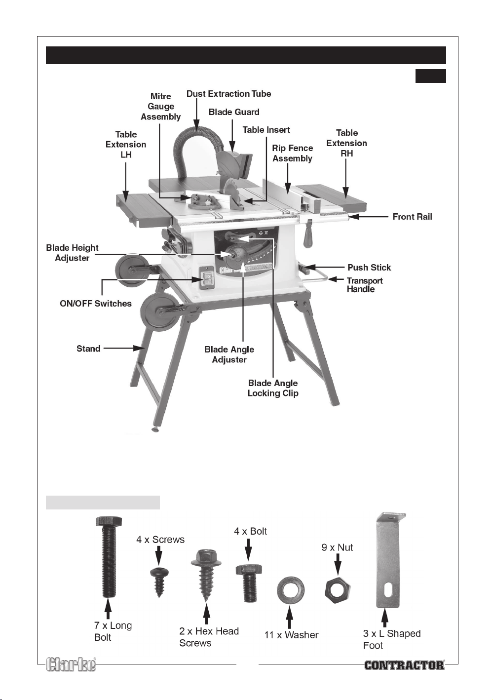
To transport the the machine, lift the table sufficient to collapse the legs at the wheel end of the stand,
then lower on to its wheels. Raise the assembly by its transport handle and collapse the other leg. The
handle may now be used to transport the table saw as required.
IMPORTANT: NEVER lift the table using the table extensions. Always lift at the table proper.
FIXINGS PACK
9
Page 10

FEATURES
1. The switch panel incorporates the ON and OFF switches.
2. A Dust Extraction Tube is provided at the rear of the machine. A vacuum extractor with a suitable
flexible hose (35mm ID.), may be connected and used either permanently or intermittently as
required.
3. The Table is provided with two slots, one each side of the saw blade, running front to back. These
slots are for use with the Mitre Gauge when cross cutting and is explained under ‘Operation’. A
scale on the Mitre Gauge indicates the angle at which the workpiece is being mitred.
4. Four holes are provided in the base so that the saw may be bolted to the table stand. Please note
that the machine MUST be firmly secured to either a workbench or the stand supplied to ensure its
complete stability.
5. The Blade Height Adjuster raises or lowers the blade.
O
6. The Blade Angle Adjuster, allows the saw blade to be tilted to any angle from 0
on the Scale on the front panel.
7. The Rip Fence is for use when rip cutting timber. It locates on the front rail and can be easily moved
or locked in place by pushing the locking handle down.
8. The Blade Guard protects the operator and must ALWAY S be in place and working
properly.
WARNING: THIS MACHINE IS NOT DESIGNED FOR ‘NON-THROUGH CUTTING’ OPERATIONS
9. The Table Insert is removable to facilitate the installation or removal of the saw blade,
and must ALWAYS be in place when the table saw is being used.
to 45O , as shown
GLOSSARY OF TERMS
Arbor The shaft on which a cutting tool is mounted.
Crosscut A cutting operation made across the width of the workpiece - across the grain.
Featherboard A device which can help guide workpieces during rip type operation.
Heel Misalignment of the blade.
Kerf The amount of material removed by the blade in a through cut.
Kickback An uncontrolled grabbing, and throwing of the workpiece back toward the
front of the saw during a rip type operation.
Leading End The end of the workpiece which, during a rip type operation, is pushed
into the cutting tool first.
Push Stick A device used to feed the workpiece through the saw during narrow ripping
type operation and which helps keep the operator’s hands well away from
the blade.
Push Block A device used for ripping type operations too narrow to allow use of a Push
stick.
Rabbet A notch in the edge of a workpiece.
Ripping A cutting operation along the length of the workpiece - in the direction of the
grain.
Riving Knife Positioned behind the saw blade to prevent wood closing and jamming after
10
Page 11
UNPACKING AND CHECKING CONTENTS
The Table Saw is shipped complete in one carton.
Separate all parts from the packing materials and check to ensure that all components are
accounted for, according to the following list, before discarding any packing material.
LIST OF CONTENTS
1. 10" Table saw x 1
2. 254 mm (10") saw blade x 1
3. Rear table x 1
4. Rear table brackets x 2
5. Cross cut extension tables x 2
6. Table saw stand x 1
7. Wheels for stand x 2
8. Blade guard x 1
9. Rip fence x 1
10. Mitre gauge x 1
11. Push stick x 1
12. Dust extraction hose x 1
13. Riving knife (with laser cutting guide attached) x 1
14. Fixings pack (nuts & bolts etc) x 1 see page 9
15. 3 x L Shaped brackets (the fix the table saw to the floor)
Should any component be missing or damaged in transit, please contact your CLARKE dealer
immediately, or CLARKE Customer Service Department on 020 8558 7400
WARNING!
DO NOT plug the table saw into the mains until it is fully assembled and checks made
according to these instructions.
REMOVING THE POLYSTRENE PACKAGING
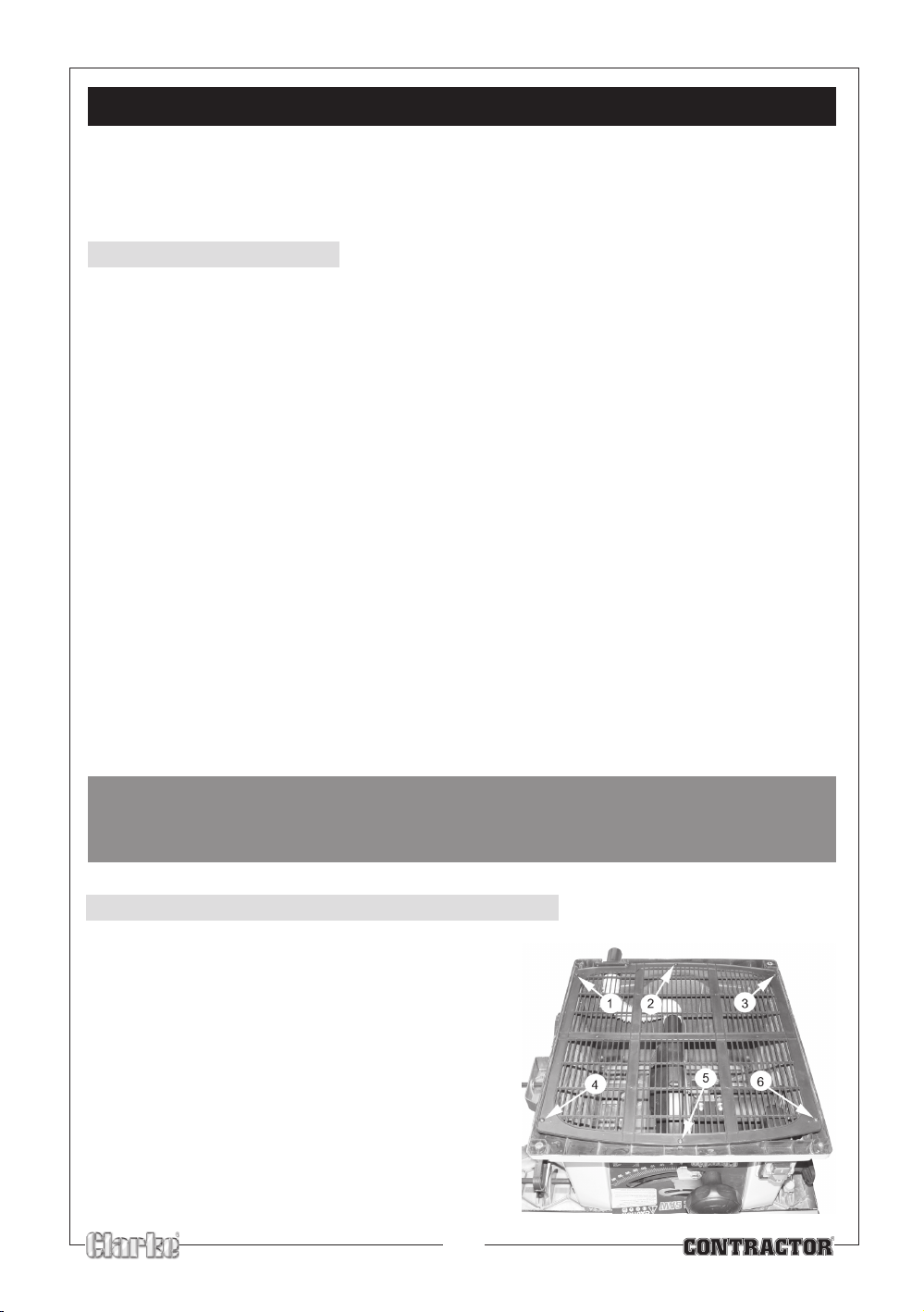
1. Turn the saw upside down and remove the six
screws that hold the bottom grill to the bottom of
the saw.
2. Remove the polystyrene packaging.
3. Replace the plastic grid and make sure that the
screws are securly tightened.
11
Page 12
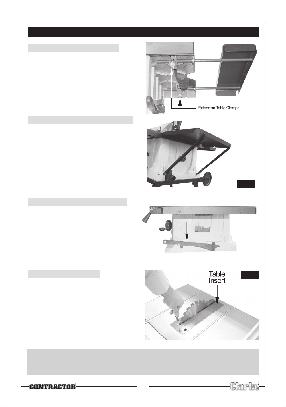
Fig.2
ASSEMBLY
Fig. 3
Fig.4
A. TABLE EXTENSIONS
1. Loosen the extension table clamps.
2. Slide the extension table into the two holes
on the side of the table saw.
3. Secure each extension table by tightening
up the extension table clamps.
B. REAR TABLE EXTENSION
1. Fit the rear table to the main body using the
bolts provided.
2. Connect the rear table to the support arms
using the bolts, washers and nuts supplied
3. Ensure the table it level and fix the support
arms to th eplastic body using the screws
provided
C. PUSH STICK STORAGE
1. Store the Push Stick in the holder provided.
D. RIVING KNIFE
1. Remove the table insert (1 countersunk
screw).
2. Raise the blade as far as possible and adjust
the blade angle, so that the blade lays at a
o
angle.
45
IMPORTANT:
Take great care to avoid contact with the saw teeth which are extremely sharp
when performing the following operations.
12
Page 13
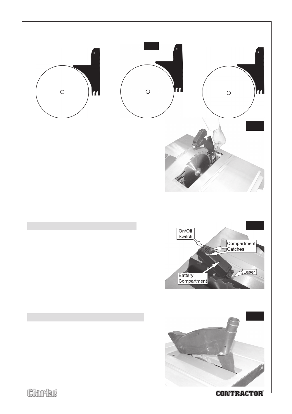
3. Slide the Riving Knife into position, and adjust the Riving knife so that a clearance of no more than
Fig.6
Fig.8
Fig.5
Fig.7
5mm exists between blade and knife, and along the full length of the riving knife, as illustrated in Fig. 5
✘
4. Tighten the riving knife securing bolt as shown in
Fig. 6.
Note:
Make sure that the Riving Knife is directly in line
with the blade at all times. If at any time it
becomes misaligned, it must be straightened
before the table saw is used.
5. When satisfied, tighten the riving knife securing
bolt before replacing the Table Insert.
E FITTING LASER BATTERIES
1. Loosen the compartment catches and rotate then
off of the battery compartment.
2. Remove the battery compartment.
3. Insert 2 AAA batteries following the polarity diagram
inside the compartment.
✘
✔
4. Replace the battery compartment and reposition
the compartment catches.
5. Tighten the compartment catches if
F FITTING THE BLADE GUARD
1. Raise the saw blade as far as possible.
2. Attach the Blade Guard to the Riving Knife, as
shown.
• The guard should be secure, but still be capable of
dropping under its own weight. Do not over tighten.
13
Page 14
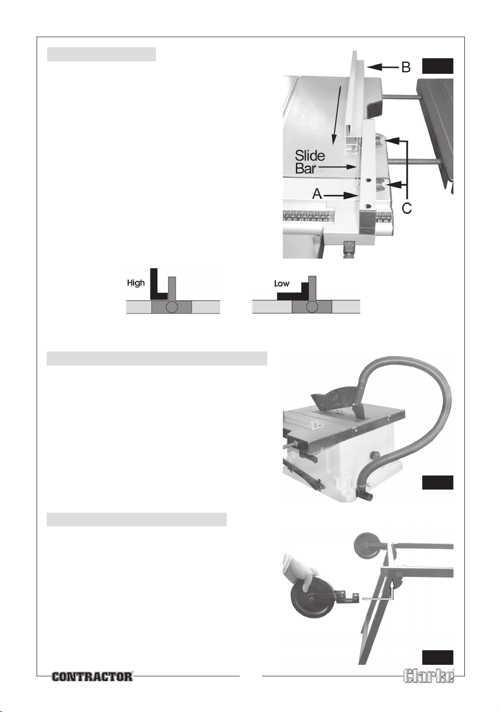
G. RIP FENCE
Fig.9
Fig.10
Fig.11
The rip fence has the following parts:
1. The handle assembly ‘A’
2. The fence ‘B’
3. Two fixings, each comprising a coach bolt and
securing knobs ‘C’.
1. Slide the handle assembly (A) into the slot in the
front rail, and push the handle down to lock the rip
fence to the table.
2. Pull the slide bar out slightly and slide the fence (B)
behind the slide bar as shown.
3. Tighten the securing knobs (C) to lock the fence to
the handle assembly.
Note: The rip Fence has two slots, allowing the fence
to be attached in the ‘high’ or ‘low’ position
H. CONNECT THE VACUUM HOSE
1. Attach the hose as shown in Fig.10
2. Connect a vacuum cleaner to the dust outlet
port on the rear of the table saw.
I. CONNECT THE WHEELS
The stand shown without the table saw fitted for
illustrative purposes only.
1. Attach the wheels as shown in Fig.11.
2. Secure in place using 2 nuts, long bolts and
spring washers supplied.
14
Page 15
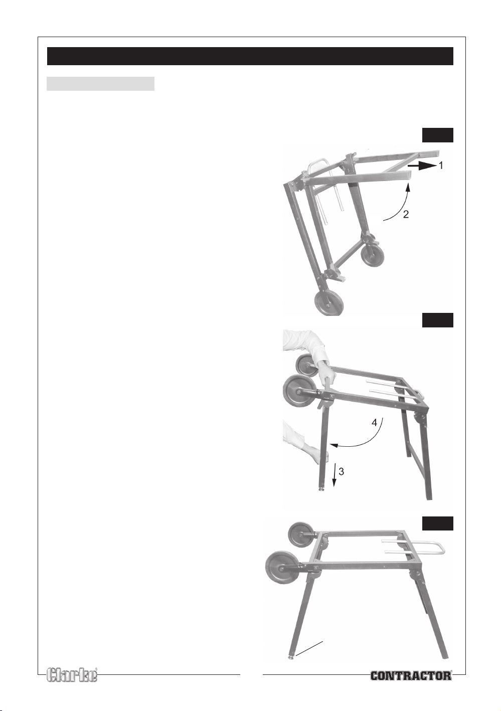
Fig.12
Fig. 13
OPENING THE STAND
Fig.14
STAND SETUP
The images are shown without the saw fitted for illustrative purposes only, the stand is actually supplied
attached to the saw.
1. Pull the front pair of legs down and out as
shown until they click into place.
2. Repeat the process with the second pair of legs.
3. The stand should appear as shown in Fig.14.
4. One of the feet can be adjusted to level the
saw. Turn the foot to raise or lower that corner.
5 You can also fix the table saw to the floor using
the supplied L shaped feet.
Adjustable foot
15
Page 16
IMPORTANT CHECKS - BEFORE STARTING
Fig.15
IMPORTANT:
Before attempting to use the machine, it is necessary to ensure the various
components are correctly adjusted, and securely fitted.
• Make sure that the blade is securely fitted.
• Ensure the Blade Guard is fitted securely and capable of dropping under its own weight.
• Remove all tools or pieces of wood from the top of the table.
• If the Rip Fence is being use, make sure it is secure before use.
• Ensure the saw Blade is at the desired height and locked in place before use.
OPERATION
STARTING AND STOPPING THE MACHINE
The ON and OFF switches are located on the front of the table saw.
1. Plug the mains plug into the mains supply.
2 Connect a vacuum cleaner nozzle to the dust outlet at the rear of the table saw.
Green
3 Press the
• The table saw will now start. Always allow the blade to reach full speed before performing any
cutting operations.
To switch the saw off:
4 Push the
• The table saw will stop.
NOTE: The blade will continue to rotate for a few seconds after the saw has been switched
off.
If during use the power is interrupted for any reason, the table saw will automatically switch OFF. You
can restart the table saw by pressing the Green ON button.
button of the switch marked ‘I’.
Red
button of the switch marked ‘O’.
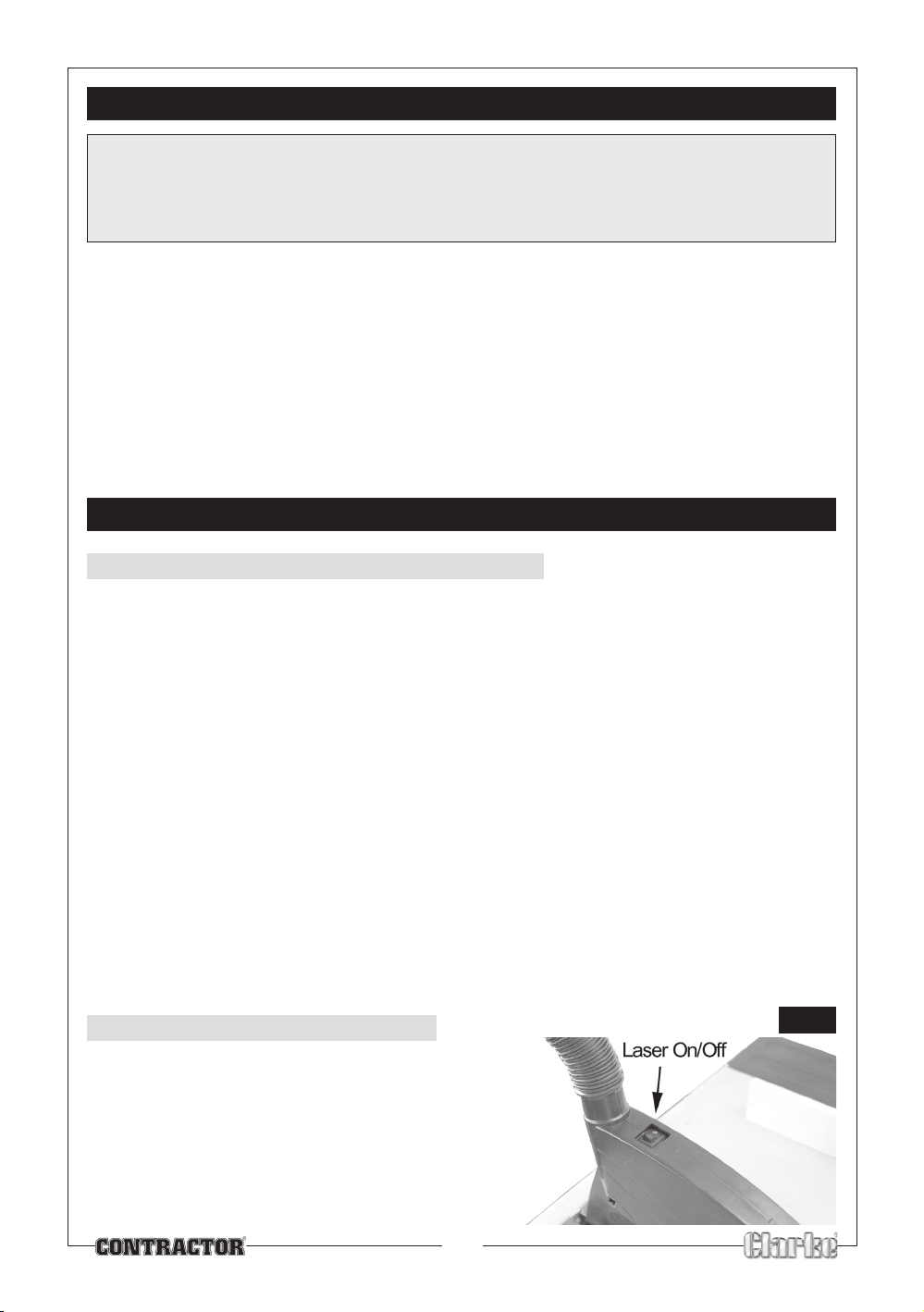
TURNING THE LASER ON/OFF.
The saw is fitted with a laser cutting guide.
1. Use the ON/Off switch to turn the laser on or off.
16
Page 17
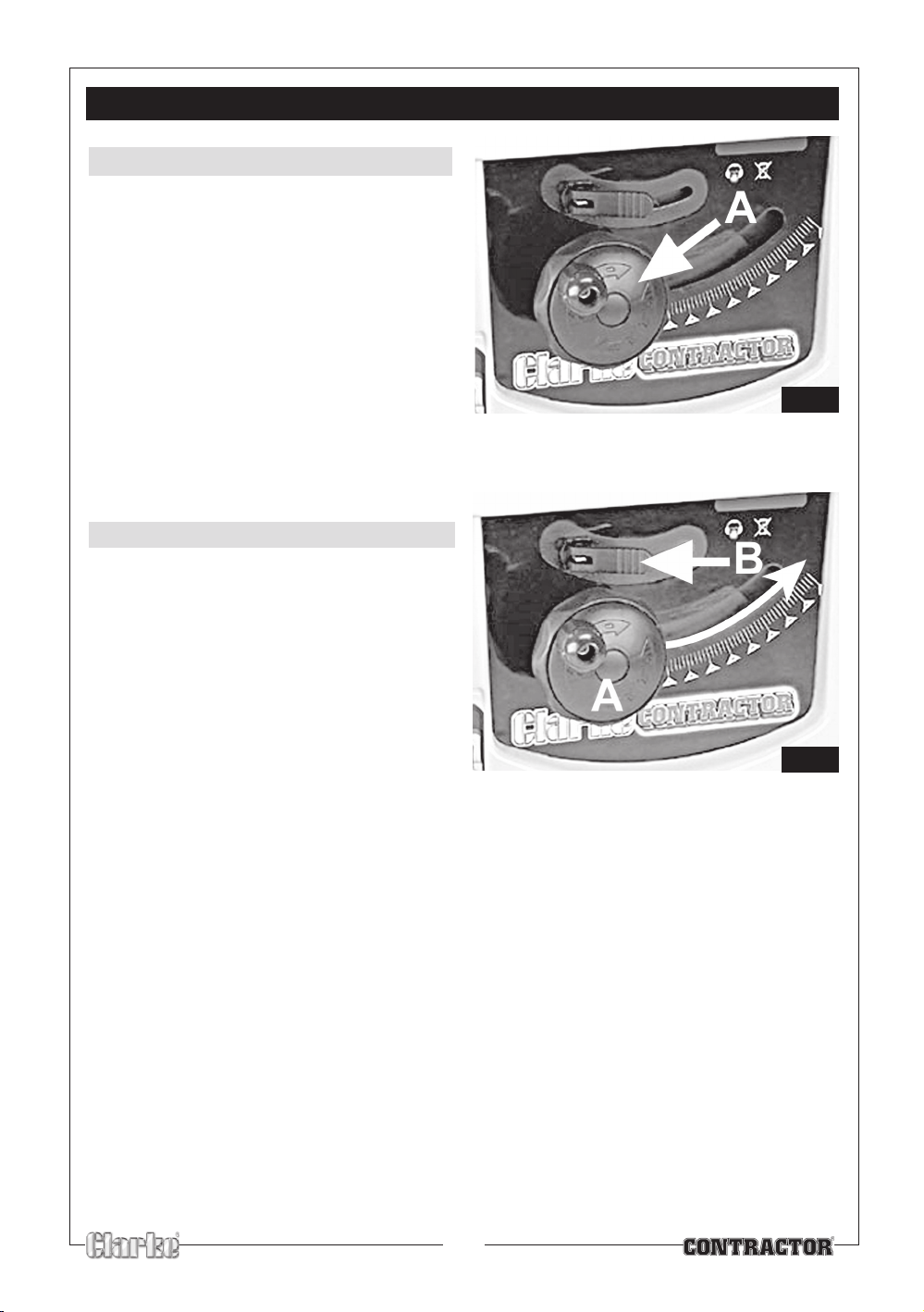
Fig.16
Fig.17
ADJUSTMENTS
CHANGING THE BLADE HEIGHT
Turn the blade height handwheel ‘A’ Fig. 16, to
adjust the height of the blade.
• Turn the blade height adjuster handwheel,
clockwise to lower the blade and
anticlockwise to raise the blade.
CHANGING THE BLADE ANGLE
Release the blade angle locking lever ‘B’ Fig 17,
by pulling the lever outwards.
• Grasp the blade angle adjustment wheel
‘A’ and rotate the outside of the
adjustment wheel Fig. 16, so that the
pointer is aligned with the required angle
shown on the angle indicator .
• Lock the blade at the desired angle by
pressing the locking lever ‘B’ firmly inwards.
17
Page 18
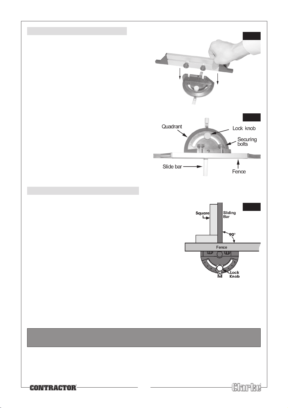
USING THE MITRE GAUGE
Fig.18
Fig.19
Fig.20
1. Screw the mitre gauge fence to the quadrant,
using the two securing wheels. As shown.
2. Slide the mitre gauge into one of the slots on the
top of the table.
3. Loosen the lock knob and set the mitre gauge to
the required angle.
4. Tighten the lock knob.
5. The calibration on the mitre gauge is suitable for
most applications but for extra accuracy, a
protractor or other measuring device should be
used when setting the cutting angle. Test the
accuracy of the angle on a piece of scrap
material before cutting the workpiece.
MITRE GAUGE ADJUSTMENT
To produce an accurate cut at 90O you should check the gauge
as follows:
1. Loosen the lock knob and, using a set square as shown , set
the slide bar at 90
2. Tighten the Lock knob and re-check with the square to ensure
no movement has taken place during the tightening process.
• The graduations on the mitre gauge provide accuracy for
average woodworking. In some cases where extreme
accuracy is required, make a trial cut and then recheck it
with an accurate square or protractor.
• When using the left hand groove, hold the workpiece firmly
against the mitre gauge head with your left hand, and push
with your right hand.
O
to the body.
• When using the right hand groove, hold the work piece with the right hand and push with the
left.
WARNING: THE RIP FENCE MUST BE REMOVED FROM THE TABLE WHEN USING THE MITRE GAUGE.
18
Page 19
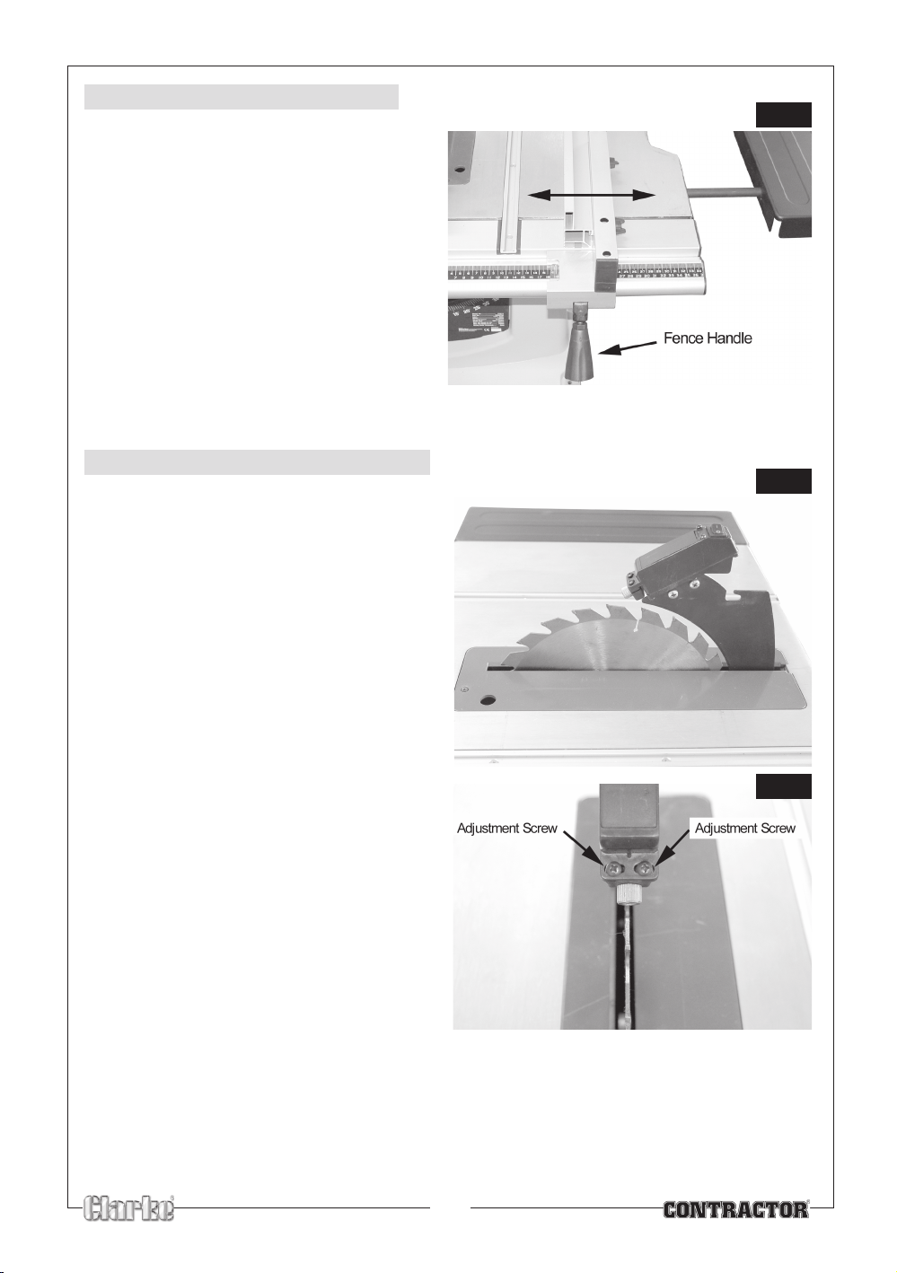
ADJUSTING THE RIP FENCE
Fig. 21
Fig. 22
Fig. 23
1. Lift the fence handle up.
2. Slide the rip fence to the position you
require.
3. Push the fence handle down to lock the Rip
Fence into place.
ADJUSTING THE LASER GUIDE
To align the laser guide proceed as follows.
o
1. Set the blade angle to 0
2. Remove the blade guard. From this point on,
take great care not to damage your hands
on the saw blade teeth.
.
3. Switch the laser guide on.
4. Carefully grip the end bezel on the laser guide
and turn it until the beam is parallel with the
blade.
5. Loosen the two adjustment screws in the
mounting bracket on the front of the laser
holder (Fig.23).
6. Move the front of the laser holder until the
beam is running along the edge of the
blade.
7. Retighten the two adjustment screws.
8. Replace the blade guard.
19
Page 20
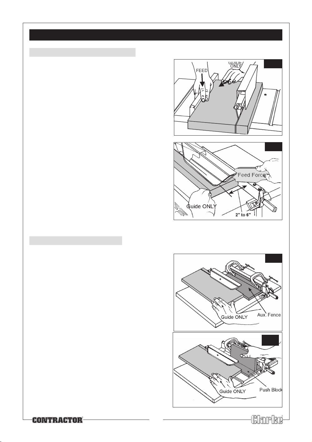
Fig.25
Fig.24
CUTTING PRACTICES
Fig.27
Fig.26
RIPPING OR RIP CUTTING
Ripping means to cut a piece of timber in the same
direction as the grain, i.e usually lengthwise.
• The rip fence can be positioned to the right or
left of the saw blade, and can be adjusted to
suit the width of cut required,
1. Lock the rip fence into position.
• When the width of rip is 150mm (6”) and wider
use your right hand to feed the workpiece, only
use left hand to guide the workpiece. (Fig.24).
• If the width of rip is narrower than 50mm (2”), the
push stick cannot be used because it will interfere
with the guard. It is therefore necessary to use an
auxiliary fence, and push block as shown in
fig.26 + fig.27.
2. Attach auxiliary fence to rip fence with two ‘G’
clamps as shown in fig.26.
3. Feed the workpiece by hand until the end is
approximately 1” from the front edge of the table.
Continue to feed using the push block until the cut is
complete.
RIP CUTTING A BEVEL
By tilting the saw blade (up to 45O), it is possible to rip cut
a bevel in your work. To do this:
1. Set the blade angle using the blade angle adjuster.
• If the workpiece is less than 150mm (6”) wide,
position the rip fence on the RIGHT SIDE of the
blade. This will provide more space between the
fence and the saw blade for the use of a push
stick.
20
Page 21
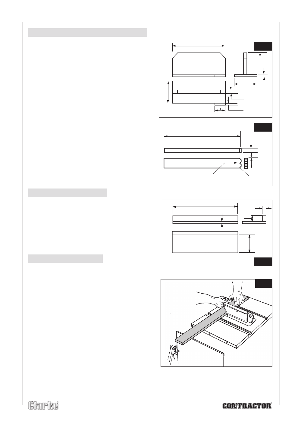
Fig.31
PUSH STICK AND PUSH BLOCK
Fig.28
Fig.29
Fig.30
Make the Push Block using pieces of 10mm plywood
and 19mm hardwood as shown in Fig.28.
• The small piece of wood 10x10x64mm should
be GLUED to the plywood. DO NOT USE NAILS
or SCREWS. This is to prevent damaging the
saw blade in the event you mistakenly cut
into the push block.
• Position the handle in the centre of the
plywood and fasten together with glue and
wood screws screwed in from below. (Ensure
the screw holes are countersunk. The screw
heads must not be proud).
Replacement Push Sticks can be made using a
suitable piece of timber as shown in Fig. 29.
AUXILIARY FENCE
Make an auxiliary fence using pieces of 10mm
plywood and 19mm hardwood. Fasten together with
glue and wood screws. Dimensions are shown in Fig.
30.
NOTE: The Push Block is used with the Auxiliary
Fence, the 120mm dimensions must be identical
on both the pieces.
CROSSCUTTING.
120mm
304mm
445mm
64mm
380mm
45° x 45° notch
10mm
Auxiliary Fence
130mm
19mm
10mm
19mm
6 x 6mm
44mm
127mm
10mm
40mm
19mm
120mm
Crosscutting is the term used to describe cuts made
in timber across the grain. This type of cut requires the
use of the MITRE GAUGE. This includes bevel cutting,
mitre cutting and compound mitre cutting
(described later in this paragraph).
1. To perform a cross cutting operation, hold the
work firmly against the mitre gauge fence as
shown in Fig.31.
2. With the timber carefully lined up with the saw
blade, the mitre gauge is gently pushed along
the groove, past the saw blade, producing the
desired cut.
• Long workpieces should be supported. A
simple arrangement is to clamp a piece of
plywood to a sawhorse as shown in Fig. 31
Cross cutting, with support
21
Page 22
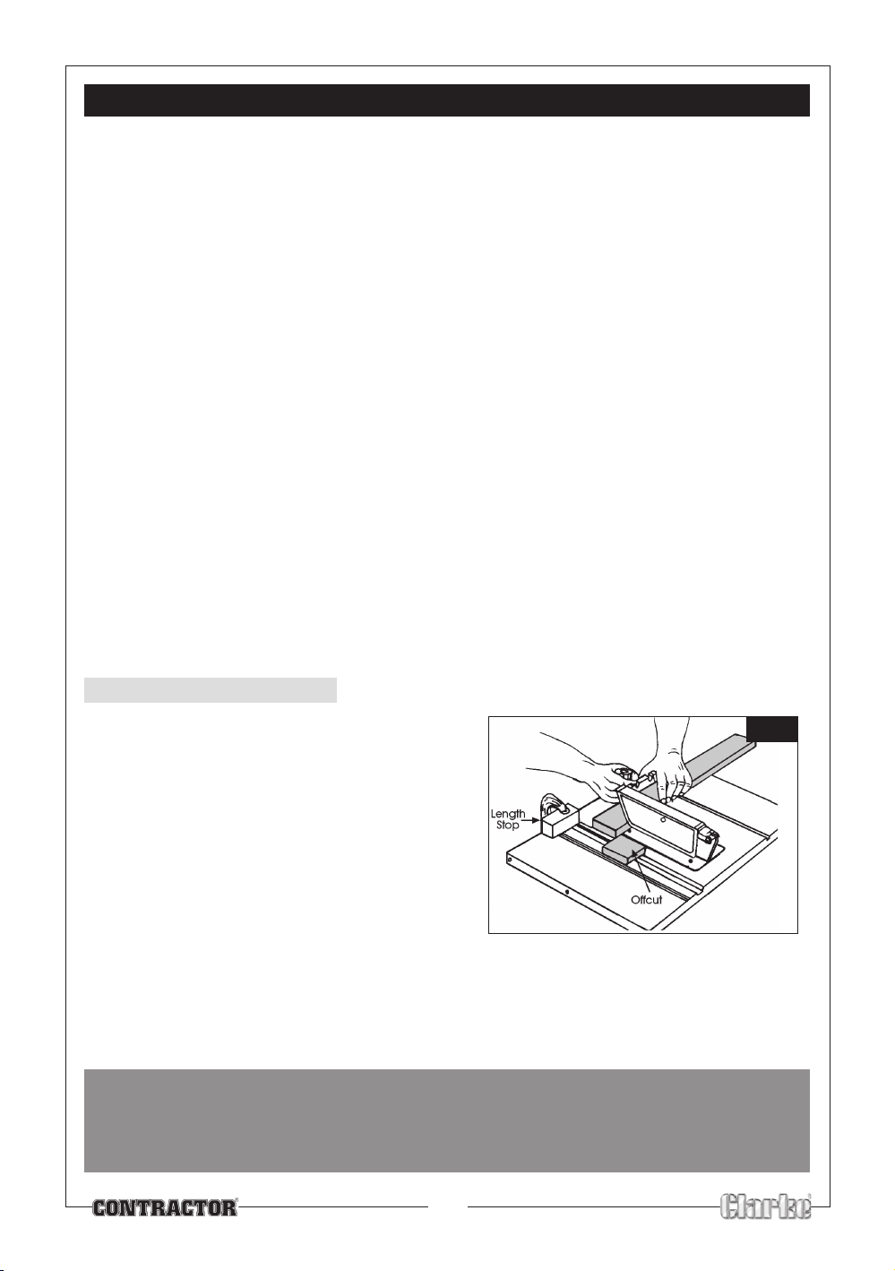
WHEN CROSSCUTTING
Fig.32
1. Do not make cuts freehand (without using the mitre gauge or other auxiliary device) the blade may
bind in the cut and cause kickback or cause your fingers or hand to slip into the blade.
2. Always lock the mitre gauge when in use.
3. Remove rip fence from table when not in use.
4. Make sure blade guard is installed (for all operations).
5. Set the saw blade height to the thickness of the wood plus 2-3mm.
6. Do not stand in front of the blade in case of a throwback (small cutoff piece caught by the back of
the blade and thrown toward the operator). Always stand slightly to one side of the blade.
7. Keep your hands clear, and away from the blade.
8. If the blade stalls or stops during the cutting process, switch the machine OFF and disconnect from
the mains supply, before you attempt to free the blade.
9. Do not reach over or behind the blade for any reason.
10. Do not pick up small pieces of cutoff material from the table. Remove them by pushing them off
the table with a stick.
11. Do not remove small pieces of cutoff material that may become trapped inside the blade guard
while the saw is running. Turn the saw off. Once the blade has stopped turning, lift the guard and
remove the trapped piece with a stick.
12. If the workpiece is warped, place the concave side down. This will prevent it from rocking while it is
being cut.
REPETITIVE CUTTING
Repetitive cutting is the term used when cutting a
quantity of pieces of the same length without having
to mark each piece.
When making repetitive cuts from a long workpiece,
make sure it is supported.
1. When making repetitive cuts, clamp a block of
wood 75mm (3”) long to the table at the desired
length to act as a length stop.
NOTE: When clamping the block, make sure that
the end of the block is well in front of the saw
blade. Make sure it is clamped securely.
2. Slide the workpiece along the mitre gauge until it touches the block, hold it securely.
When cutting long workpieces, make sure the end is supported.
3. Make the cut, pull the workpiece back and push the off-cut off of the table using a
push stick, DO NOT ATTEMPT TO PICK IT UP AS THIS COULD ENDANGER YOUR HANDS.
WARNING!
NEVER USE THE RIP FENCE AS A LENGTH STOP BECAUSE THE CUT-OFF PIECE COULD BIND
BETWEEN THE FENCE AND THE BLADE CAUSING A KICKBACK.
Repetitive cutting
22
Page 23
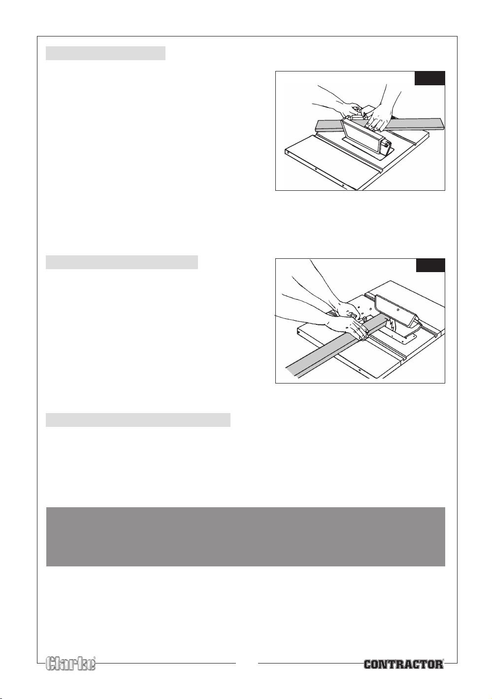
Fig.34
Fig.33
MITRE CUTTING
Mitre cutting is the term used for cutting at an angle
other than 90
Adjust the mitre gauge to the desired angle, and lock
it.
• The mitre gauge may be used in either of the
• When using the mitre gauge in the LEFT hand
• When using the RIGHT hand groove, hold the
O
to the edge of the wood.
grooves in the table.
groove, hold the workpiece firmly against the
mitre gauge with your left hand and push with
your right.
workpiece with your RIGHT HAND and the lock
knob with your left hand.
BEVEL CROSSCUTTING
Bevel crosscutting is the same as crosscutting except
that the wood is also cut at an angle, other than 90
degrees with the flat side of the wood.
Adjust the blade to the desired height and angle.
• Use the mitre gauge in the right hand groove.
Do not use the left hand groove, the blade
guard will interfere.
• Hold the workpiece with your right hand and
the push with your left hand.
COMPOUND MITRE CUTTING
Compound mitre cutting is a combination of mitre cutting and bevel crosscutting. The cut is made at an
angle other than 90O to both the edge and the flat side of the wood.
• Adjust the mitre gauge and the blade to the desired angle.
• Make sure the mitre gauge body is locked.
WARNING!
WHEN MITRE CUTTING, AN AREA OF BLADE IS EXPOSED.
GREAT CARE MUST BE TAKEN WHEN USING THE TABLE SAW FOR THIS OPERATION.
23
Page 24
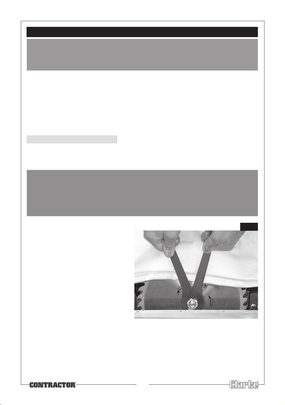
MAINTENANCE
Fig.35
WARNING!
FOR YOUR OWN SAFETY, SWITCH MACHINE OFF AND REMOVE PLUG FROM POWER SOURCE
BEFORE ADJUSTING, MAINTAINING OR LUBRICATING YOUR SAW.
Do not allow sawdust to accumulate inside the saw. Use a dust extractor if possible, if not, frequently
blow out any dust that may accumulate inside the saw cabinet and the motor.
Inspect the power cable frequently. If it is worn or cut, or damaged in any way, have it replaced
immediately.
NOTE: Do not use any of the following to clean this table saw: gasoline, carbon tetrachloride,
chlorinated cleaning solvents, ammonia and household detergents which contain ammonia.
A coat of wax applied to the table will help to keep the surface clean and allow wood being cut to slide
more freely.
CHANGING THE BLADE
• Use only Clarke Blades, (see parts list for part numbers).
• Replace the blade when teeth become damaged or dull.
WARNING!
TO PREVENT PERSONAL INJURY, ALWAYS DISCONNECT PLUG FROM POWER SOURCE BEFORE
CHANGING BLADES.
TAKE GREAT CARE WHEN HANDLING SAW BLADES - THE TEETH ARE EXTREMELY SHARP, AND
CARELESSNESS CAN CAUSE SERIOUS PERSONAL INJURY
1. Remove the table insert.
2. Raise the blade as far as possible, then
remove the blade guard.
It also helps to turn the blade angle
adjuster so as to lay the blade on its
side.
NOTE: From this point, take great care to
avoid contact with the tips of the saw
blade, preferably place a thick cloth
over the teeth, as shown in Fig 35.
3. Undo the Blade securing nut, using the
two spanners provided, one to engage
with the flats on the outer flange, the
other to remove the nut.
4. Replace the blade in reverse order, ensuring the teeth point down towards the table at the
front, and it sits snugly on the boss on the inner flange before replacing the outer flange and
tightening the securing nut.
24
Page 25
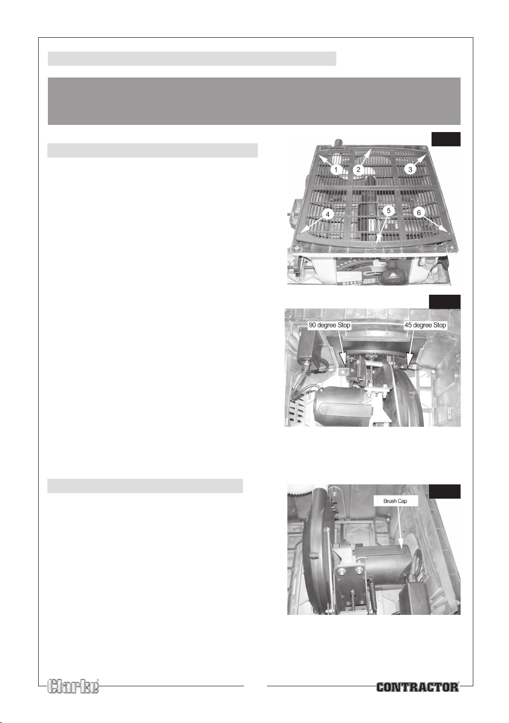
ADJUSTING 90 AND 45 DEGREE POSITIVE STOPS
Fig.37
Fig.38
Fig.36
WARNING!
ENSURE THE PLUG IS DISCONNECTED FROM THE POWER SUPPLY BEFORE PROCEEDING
ADJUSTING THE POSITIVE STOPS
1. Raise the blade to maximum height.
2. Turn machine so that it rests on the table top’s
side edge and is supported in some way,
ensuring it is stable.
3. Remove the bottom grill by removing the 6
screws shown.
4. Adjust the Positive stops, indicated in Fig. 37, as
required, checking the blade angle using a set
square and protractor as necessary.
5. When completely satisfied, ensure the stops are
properly locked, then replace the bottom grille.
RENEWING MOTOR BRUSHES
1. Turn machine so that it rests on the table top’s side
edge and is supported in some way, ensuring it is
stable.
2. Remove bottom grille.
3. Unscrew and remove the Brush Caps, (one either side
of the motor housing), then withdraw the brush with
springs attached.
4. Carefully insert replacement brushes and replace the
screw on caps.
NOTE: Always replace both brushes at the same time.
25
Page 26
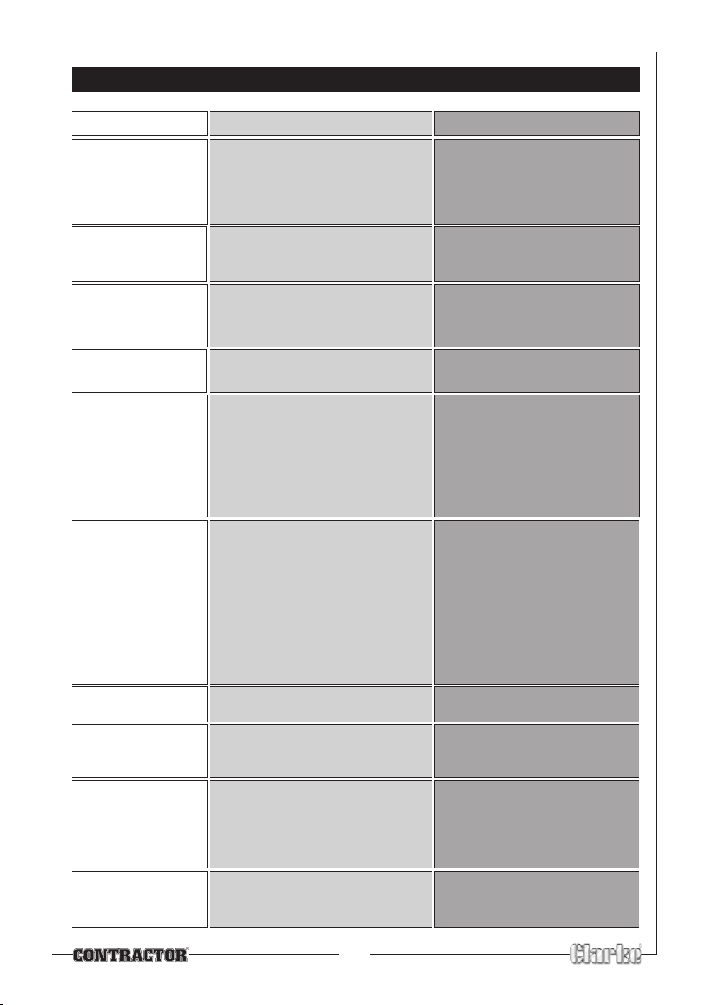
TROUBLE SHOOTING
TROUBLE PROBABLE CAUSE REMEDY
Saw will not start 1. Saw not plugged in 1. Plug in the machine
2. Fuse blown 2. Replace fuse
3. Power cable damaged 3. Have cable replaced by
authorised service centre
Does not make 1. Positive stops not adjusted 1. Check blade with square and
accurate 45O and 90
Rip Cuts and adjust pointer to zero
Material Pinches 1. Rip fence not aligned with blade 1. Check and adjust rip fence
Blade When Ripping 2. Warped wood, edge against 2. Select another piece of wood
Material binds on 1. Riving knife not aligned correctly 1. Check and align Riving knife with
Riving Knife with blade blade
Saw makes 1. Dull blade 1. Replace blade
unsatisfactory cuts 2. Blade mounted backwards 2. Turn blade around
Material kicked back 1. Rip fence out of alignment 1. Align rip fence with blade
from blade slot 2. Riving knife not aligned with blade 2. Align Riving knife with blade
O
fence not straight
3. Gum or pitch on blade 3. Remove blade and clean with
4. Incorrect blade for work 4. Change the blade
5. Gum or pitch on table causing 5. Clean table with turpentine and
erratic feed steel wool and apply wax
3. Feeding stock without rip fence 3. Install and use rip fence
4. Riving knife not in place 4. Install and use Riving knife with
5. Letting go of material before it is 5. Push material all the way past
all the way past the saw blade blade before releasing work
6. Dull blade 6. Replace blade
7. Mitre angle lock knob is not tight 7. Tighten knob
correctly adjust positive stops
turpentine and coarse steel wool
guard
Blade does not raise 1. Sawdust and dirt in raising and 1. Brush or blow out loose dust
or tilt freely tilting mechanism and dirt
Blade does not come 1. Extension cable too light or too 1. Replace with adequate size
up to speed long cable
2. Low voltage 2. Contact your electric company
Machine vibrates 1. Saw not mounted securely to 1. Tighten all mounting hardware
Does not make 1. Mitre gauge out of adjustment 1. Adjust mitre gauge
accurate 45O and
90O crosscuts
Stand or work bench
2. Stand or bench on uneven floor 2. Reposition on flat level surface
Fasten to floor if necessary
3. Damaged saw blade 3. Replace blade
26
Page 27
PARTS LISTS
No. Description Qty Part No
1 Side extension table 2 DDCTS12001
2 Rubber foot 2 DDCTS12002
3 Flat washer 39 DDCTS12003
4 Cross tapping screw 2 DDCTS12004
5 Cross tapping screw 8 DDCTS12005
6 Slide bar A 1 DDCTS12006
7 Main table 1 DDCTS12007
8 Block A 2 DDCTS12008
9 Left block 1 DDCTS12009
10 Mitre guage 1 DDCTS12010
11 Knob 5 DDCTS12011
12 Pan screw 2 DDCTS12012
13 Washer 5 DDCTS12013
14 Indicator 1 DDCTS12014
15 Mitre guage slider 1 DDCTS12015
16 Insert plate 1 DDCTS12016
17 Cross screw 1 DDCTS12017
18 Bolt 2 DDCTS12018
19 Slot sleeve 1 DDCTS12019
20 Sliding carriage A 1 DDCTS12020
21 Nut 10 DDCTS12021
22 Screw 4 DDCTS12022
23 Flat washer 5 DDCTS12023
24 Block B 2 DDCTS12024
25 Fence 1 DDCTS12025
26 Sliding seat 1 DDCTS12026
27 Lock handle 1 DDCTS12027
28 Powercord set 1 DDCTS12028
29 Cam 1 DDCTS12029
30 Locking washer 1 DDCTS12030
31 Spindle 1 DDCTS12031
32 Cord holder 2 DDCTS12032
33 Tapping screw 14 DDCTS12033
34 Switch box 1 DDCTS12034
35 Switch 1 DDCTS12035
36 Screw bolt 6 DDCTS12036
37 Special nut 2 DDCTS12037
38 Wheels 2 DDCTS12038
39 Wheel bracket 2 DDCTS12039
40 Flat washer 12 DDCTS12040
No. Description Qty Part No
41 Hex bolt 2 DDCTS12041
42 Hex bolt 1 DDCTS12042
43 Left stand assembly 1 DDCTS12043
44 Foot block 3 DDCTS12044
45 Adjustable foot 1 DDCTS12045
46 Hex nut 5 DDCTS12046
47 Special nut 7 DDCTS12047
48 Base plate 1 DDCTS12048
49 Plastic house 1 DDCTS12049
50 Blade guard 1 DDCTS12050
51 Plastic plate 1 DDCTS12051
52 Right stand assembly 1 DDCTS12052
53 Drawer handle 1 DDCTS12053
54 Pin 4 DDCTS12054
55 Mitre guage base 1 DDCTS12055
56 Right block 2 DDCTS12056
57 Hex bolt 4 DDCTS12057
58 Tapping screw 1 DDCTS12058
59 Dust port 1 DDCTS12059
60 Hex bolt 9 DDCTS12060
61 Blade holder 1 DDCTS12061
62 Blade fix knob 1 DDCTS12062
63 Handle 2 DDCTS12063
64 Dust tube 1 DDCTS12064
65 Slide bar tube 4 DDCTS12065
66 Retaining ring 4 DDCTS12066
67 Tapping screw 2 DDCTS12067
68 Side support 2 DDCTS12068
69 Rear table 1 DDCTS12069
70 Slide bar B 1 DDCTS12070
71 Tapping screw 6 DDCTS12071
72 Washer 1 DDCTS12072
73 Right guard 1 DDCTS12073
74 Riving knife 1 DDCTS12074
75 Pan screw 3 DDCTS12075
76 Spring 4 DDCTS12076
77 Laser assembly 1 DDCTS12077
78 Special nut 2 DDCTS12078
79 Pan screw 4 DDCTS12079
80 Bolt 1 DDCTS12080
27
Page 28
No. Description Qty Part NoNo. Description Qty Part No
81 Slide bar clamper 4 DDCTS12081
82 Left guard 1 DDCTS12082
83 Screw 1 DDCTS12083
84 Handle B 1 DDCTS12084
85 Handle A 1 DDCTS12085
86 Handle cover 1 DDCTS12086
87 Handle B 1 DDCTS12087
88 Handle A 1 DDCTS12088
89 Screw 1 DDCTS12089
90 Indicator 1 DDCTS12090
91 Front table 1 DDCTS12091
92 Rock 1 DDCTS12092
93 Nut 3 DDCTS12093
94 Protect plate 1 DDCTS12094
95 Torque spring 1 DDCTS12095
96 Small plate 1 DDCTS12096
97 Big washer 1 DDCTS12097
98 Riving knif bracket 1 DDCTS12098
99 Retain ring 1 DDCTS12099
100 Dust suction cover A 1 DDCTS12100
101 Shaft assembly 1 DDCTS12101
102 Saw blade 1 DDCTS12102
103 Nut 1 DDCTS12103
104 Dust suction cover B 1 DDCTS12104
105 Blade flange 1 DDCTS12105
106 Bolt 1 DDCTS12106
107 Big washer 1 DDCTS12107
108 Riving knif clamp 1 DDCTS12108
109 Screw 4 DDCTS12109
110 Spring washer 4 DDCTS12110
111 Flat washer 4 DDCTS12111
112 Riving knife bracket 1 DDCTS12112
113 Nut 5 DDCTS12113
114 Screw 4 DDCTS12114
115 Bearing 2 DDCTS12115
116 Retaining ring 1 DDCTS12116
117 Screw 4 DDCTS12117
118 Spring washer 4 DDCTS12118
119 Support bar 1 DDCTS12119
120 Screw 2 DDCTS12120
121 Thread spindle 2 DDCTS12121
122 Bolt 2 DDCTS12122
123 Spring 2 DDCTS12123
124 Gear 1 DDCTS12124
125 Belt 1 DDCTS12125
126 Driven wheel 1 DDCTS12126
127 Clamp B 1 DDCTS12127
128 Spring 4 DDCTS12128
129 Motor assembly 1 DDCTS12129
130 Bolt 2 DDCTS12130
131 Screw 1 DDCTS12131
132 Big washer 7 DDCTS12132
133 Screw 1 DDCTS12133
134 Drive wheel 1 DDCTS12134
135 Bracket frame 1 DDCTS12135
136 Rotation guide 1 DDCTS12136
137 Thread bar 1 DDCTS12137
138 Pin 1 DDCTS12138
139 Clamp A 1 DDCTS12139
140 Drive shaft assy 1 DDCTS12140
141 Washer 1 DDCTS12141
142 Bolt 1 DDCTS12142
143 Handle 1 DDCTS12143
144 Pin 1 DDCTS12144
145 Sleeve 1 DDCTS12145
146 Slide block 3 DDCTS12146
147 Spring 8 DDCTS12147
148 Slide slot 1 DDCTS12148
149 Indicator 1 DDCTS12149
150 Flat washer 7 DDCTS12150
151 Bracket assembly 1 DDCTS12151
152 Spring 4 DDCTS12152
153 Washer 1 DDCTS12153
154 Spindle retaining ring 1 DDCTS12154
155 Blade clamp 2 DDCTS12155
156 Nut 2 DDCTS12156
157 Bolt 2 DDCTS12157
158 Block B 2 DDCTS12158
159 Mitre gauge fence 1 DDCTS12159
160 Spring 1 DDCTS12160
28
Page 29
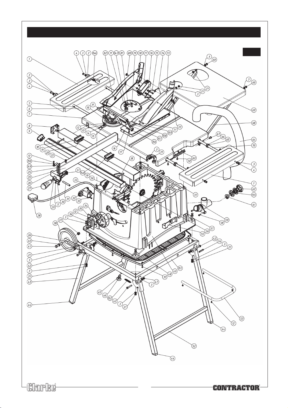
PARTS DIAGRAM
Fig.37
29
Page 30
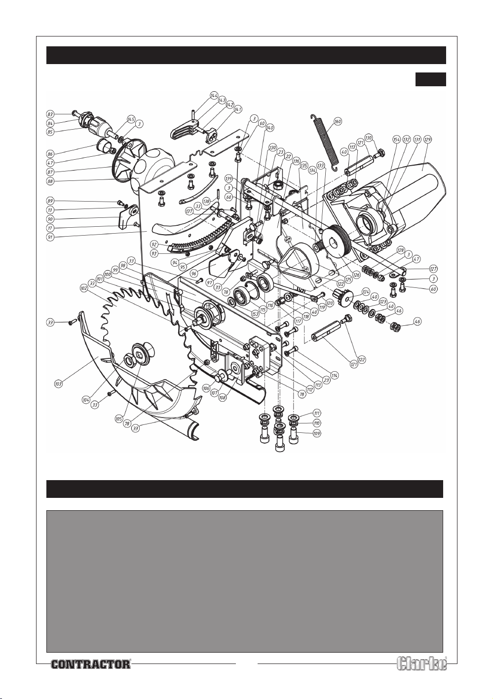
PARTS DIAGRAM
Fig.38
PARTS AND SERVICE CONTACTS
For Spare Parts and Service, please contact your nearest dealer,
or CLARKE International, on one of the following numbers.
PARTS & SERVICE TEL: 020 8988 7400
PARTS & SERVICE FAX: 020 8558 3622
or e-mail as follows:
PARTS: [email protected]
SERVICE: [email protected]
30
Page 31

31
Page 32

32
 Loading...